


Fiberglass-insulated wire plays a critical role in modern transformer manufacturing—particularly in dry-type transformers, traction transformers, H/C-class power transformers, rectifier transformers, and reactors—where high-temperature operation, reliability, and extended service life (≥30 years) are essential. Its core advantages stem from a composite insulation system comprising alkali-free glass fiber and insulating varnish coating, enabling continuous operation at 155–220 °C, excellent mechanical strength, moisture/chemical resistance, and long-term durability.
This document provides a technical overview of fiberglass-insulated wire applications across transformer types, covering typical use cases, corresponding NEMA MW specifications, Vacuum Pressure Impregnation (VPI) process compatibility, key selection criteria, and common failure modes—serving as a reference for transformer R&D engineers and procurement professionals.
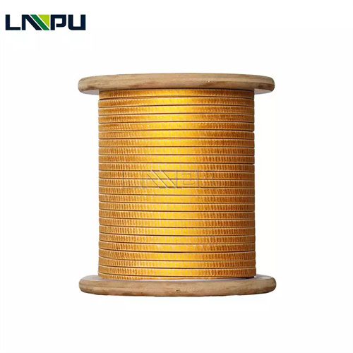
I. Functional Role of Fiberglass-Insulated Wire in Transformers
In transformer windings, fiberglass-insulated wire fulfills the following functions:
Electrical Insulation Function: The combined insulation of fiberglass layer and enamel coating provides turn-to-turn, phase-to-phase, and ground insulation, with dielectric strength ranging from 1.5 to 3.5 kV per layer.
Current-Carrying and Current-Collecting Function: The copper conductor carries operating current, with resistivity ≤ 0.01724 Ω·mm²/m @ 20 °C.
Mechanical Support and Short-Circuit Withstand Function: Glass fiber tensile strength ≥ 1.5 GPa enables windings to withstand enormous electromagnetic forces during system short circuits, complying with GB 1094.5 and IEC 60076-5.
Thermal Dissipation Function: The composite insulation system (fiberglass + enamel coating) exhibits favorable thermal conduction properties, facilitating heat dissipation from windings and reducing temperature rise.
Long-Term High-Temperature Operation Function: F/H/C-class fiberglass-insulated wire supports continuous operation at 155–220 °C—significantly exceeding the 130 °C limit of standard enameled wire.
II. Typical Application Scenarios of Fiberglass-Insulated Wire in Transformers
2.1 Dry-Type Transformers
Dry-type transformers rely on solid insulation without transformer oil, demanding high thermal class and moisture resistance from winding conductors. F- and H-class dry-type transformers represent the primary application domain for fiberglass-insulated wire.
H-class dry-type transformers commonly employ MW 43-C or MW 48-C fiberglass-insulated flat wire for both HV and LV windings, covering capacities from 0.5 kVA to 20 MVA and voltage ratings up to 35 kV. Compliant with GB 1094.11 and IEC 60076-11.
C-class dry-type transformers utilize VFG-varnish-impregnated fiberglass-insulated flat wire combined with mica tape insulation. Corresponding standards include NEMA MW 65-C and IEC 60317-46—suitable for high-temperature environments or applications requiring enhanced fire safety.
2.2 Traction Transformers
Traction transformers for rail transit systems are mounted on train rooftops or underframes, requiring H-class (or higher) thermal rating, vibration resistance, and 30-year design life. Fiberglass-insulated flat wire models MW 48-C and MW 53-C serve as HV/LV winding conductors, integrated with VPI (Vacuum Pressure Impregnation) processing. Dielectric strength and mechanical integrity fully meet IEC 60310 and IEC 60076 series requirements.
Typical dimensions: flat wire thickness 1.12–3.55 mm; width 5.00–12.50 mm; H-class insulating varnish coating; double-layer fiberglass; post-VPI overall insulation strength significantly enhanced.
2.3 Power Transformers
For large oil-immersed power transformers rated ≥110 kV, paper-wrapped wire remains dominant. However, certain H-class oil-immersed units adopt fiberglass-insulated wire + enamel coating composite insulation to improve thermal performance and mechanical robustness.
Advantages in oil-immersed transformers: superior short-circuit withstand capability, high mechanical strength, and stable performance at elevated oil temperatures (120–140 °C). NEMA MW 47-C and MW 48-C fiberglass-insulated flat wire—processed via VPI—provides a stable mechanical backbone within the oil-paper-fiberglass triple-insulation system.
2.4 Rectifier Transformers
Rectifier transformers are used in electrochemical processes, electrolysis, HVDC transmission, and front-end inverters—subjected to harmonic currents, ripple currents, and DC bias under complex operating conditions, resulting in high operating temperatures (hot-spot temperatures up to 180 °C).
Fiberglass-insulated flat wire models MW 48-C and MW 53-C serve as winding conductors in rectifier transformers. Their H-class thermal rating and high mechanical strength accommodate additional losses and temperature rise induced by harmonic currents. Post-VPI treatment further enhances dielectric strength and moisture resistance, meeting IEC 60146 and IEEE C57.18 rectifier transformer standards.
2.5 Reactors
Reactors—including series reactors, shunt reactors, current-limiting reactors, and smoothing reactors—operate under high current, elevated temperature, and substantial mechanical stress. H/C-class fiberglass-insulated flat wire (MW 48-C, MW 53-C), processed via VPI, is the preferred winding conductor solution for H/C-class reactors.
2.6 H/C-Class Electric Furnace Transformers
Electric furnace transformers—including arc furnaces for steelmaking, submerged arc furnaces, and medium-frequency induction furnaces—endure severe load fluctuations and short-circuit impacts, accompanied by high operating temperatures and intense mechanical vibration. H-class fiberglass-insulated flat wire (MW 43-C, MW 48-C) serves as the winding conductor, capable of withstanding electromagnetic forces generated by short-circuit currents of 30–100 kA, compliant with IEEE C57.13 and IEC 60076 series standards.
2.7 Wind and Photovoltaic Transformers
Box-type transformers for wind farms and photovoltaic power plants are installed outdoors, inside turbine towers, or on rooftops—exposed to harsh environmental conditions including high humidity, salt fog, thermal cycling, and vibration. The high moisture resistance, salt-fog corrosion resistance, and vibration fatigue resistance of H-class fiberglass-insulated wire make it the preferred material for wind/PV transformers, conforming to IEC 61400 and IEC 62116 renewable energy standards.
2.8 Nuclear Power Transformers
2.9 Marine and Offshore Engineering Transformers
Transformers for ships, offshore platforms, and marine engineering applications operate under severe environmental conditions—including salt fog, high humidity, mechanical vibration, and rolling motion. H-class glass-fiber-wrapped flat wire MW 43-C and MW 48-C—paired with Vacuum Pressure Impregnation (VPI) processing—deliver excellent moisture resistance, corrosion resistance against salt fog, and anti-vibration performance, fully complying with marine classification society standards such as IEC 60092, ABS, DNV, and LR.
2.10 Fire-Resistant and Explosion-Proof Transformers
In fire- and explosion-hazardous environments—including underground substations, coal mines, and chemical plants—transformer insulation materials must exhibit flame retardancy, low smoke emission, and low toxicity. Glass-fiber-wrapped magnet wire combined with Nomex paper insulation and epoxy resin encapsulation achieves UL 94 V-0 flame-retardant rating and complies with explosion-proof standards including IEC 60079 and GB 3836.
III. Corresponding Specifications of Glass-Fiber-Wrapped Magnet Wire for Transformer Applications
The following NEMA MW 1000 specifications for glass-fiber-wrapped magnet wire are matched to distinct transformer application scenarios, in accordance with ANSI/NEMA MW 1000-2018, IEC 60317, and GB/T 7672:
| NEMA Specification | Conductor | Glass-Fiber Layers | Impregnating Varnish | Thermal Class | Typical Transformer Application |
|---|---|---|---|---|---|
| MW 42-C | Flat wire | Single-layer | Polyester / oil-based | F 155℃ | Low-voltage windings of F-class dry-type transformers |
| MW 43-C | Flat wire | Single-layer | Polyester + silicone | H 180℃ | H-class dry-type transformers, rectifier transformers |
| MW 46-C | Flat wire | Double-layer polyester-glass | Polyester | F 155℃ | High-density windings of F-class dry-type transformers |
| MW 48-C | Flat wire | Double-layer | Polyester + silicone | H 180℃ | Traction transformers, reactors, rectifier transformers |
| MW 50-C | Round wire | Single-layer | High-temperature organic varnish | H 180℃ | Lead-out wires, tap windings, auxiliary windings |
| MW 51-C | Round wire | Double-layer | High-temperature organic varnish | H 180℃ | Windings of wind-power and photovoltaic transformers |
| MW 52-C | Flat wire | Single-layer | High-temperature organic varnish | H 180℃ | H-class reactors, auxiliary transformers |
| MW 53-C | Flat wire | Double-layer | High-temperature organic varnish | H 180℃ | Main windings of H/C-class transformers |
| MW 65-C | Round/flat wire | Multi-layer + mica | Polyimide | C 220℃ | Nuclear power transformers, C-class dry-type transformers |
IV. Vacuum Pressure Impregnation (VPI) Process for Glass-Fiber-Wrapped Magnet Wire in Transformers
VPI is the core complementary process for glass-fiber-wrapped magnet wire used in transformer windings, significantly enhancing overall insulation strength and moisture resistance.
VPI Process Flow:
- Pre-baking: 100℃ × 4 h to remove moisture;
- Vacuum evacuation: residual pressure ≤ 100 Pa, held for 2–4 h;
- Varnish injection: varnish introduced under vacuum;
- Pressure impregnation: 0.2–0.6 MPa, held for 4–8 h;
- Excess varnish drainage;
- Atmospheric drip-drying: 30 min;
- Curing: 130–240℃ × 4–10 h, per varnish thermal class.
Critical VPI Parameters:
- Varnish viscosity @ 25℃: 250–450 mPa·s;
- Vacuum level: ≤ 100 Pa;
- Impregnation pressure: 0.2–0.6 MPa;
- Number of impregnation cycles: 1–3, determined by required voltage resistance level.
VPI Requirements for Glass-Fiber-Wrapped Magnet Wire:
- Glass-fiber layer must be compatible with vacuum-grade varnishes—zero or low solvent volatility;
- Copper conductor surface requires passivation or micro-etching to enhance enamel coating adhesion;
- Curing temperature profile must align precisely with the thermal class of the varnish system.
Performance of VPI-Treated Glass-Fiber-Wrapped Magnet Wire Windings:
- Dielectric strength increased by 30%–80%;
- Moisture resistance significantly improved—stable dielectric loss after 96 h at 40℃/95% RH;
- Enamel coating, glass-fiber layer, and copper conductor form an integrated insulation structure;
- Mechanical strength upgraded by one grade;
- Service life extended by 1.5×–2×.
V. Failure Modes of Glass-Fiber-Wrapped Magnet Wire in Transformers
Typical failure modes and underlying mechanisms for glass-fiber-wrapped magnet wire in transformer applications:
Enamel Coating Aging and Cracking: Thermal oxidative degradation of enamel coating during prolonged high-temperature operation leads to loss of elasticity and adhesion. Improvement measures: Select enamel coatings with higher thermal class; maintain long-term operating temperature at least 20℃ below the enamel’s thermal index.
Glass-Fiber Abrasion and Penetration: Mechanical damage—including scratching or puncturing of the glass-fiber layer during winding assembly—causes turn-to-turn short circuits. Improvement measures: Use double-layer glass-fiber magnet wire (e.g., MW 47-C, MW 48-C, MW 53-C); deburr all assembly tools; perform partial discharge (PD) testing prior to final assembly.
Reduced Moisture Resistance: Moisture absorption by glass fiber in high-humidity environments increases dielectric loss. Improvement measures: Apply VPI process; select silicone-based varnishes (e.g., MW 44-C, MW 50-C, MW 52-C); implement hermetic or moisture-proof packaging and sealing design.
Incomplete VPI Impregnation: Trapped air bubbles or insufficient varnish penetration within the glass-fiber layer induce localized partial discharge. Improvement measures: Strictly control vacuum level and impregnation pressure; increase number of impregnation cycles; use only vacuum-compatible varnishes.
Short-Circuit Deformation and Insulation Damage: Following a system short-circuit event, winding deformation occurs and the fiberglass layer tears. Improvement measures: Select high-strength fiberglass-covered magnet wire; optimize winding clamping process with press plate clamping force of 0.3–0.5 MPa; verify short-circuit withstand capability per IEC 60076-5.
VI. Material Selection Guidelines for Fiberglass-Covered Magnet Wire in Transformers
Transformer manufacturers are advised to follow these steps when selecting fiberglass-covered magnet wire:
Step 1: Determine Thermal Class Select thermal class based on transformer insulation rating: Class F (155 °C), Class H (180 °C), or Class C (220 °C). Allow for safety margin—long-term operating temperature should be at least 20 °C below the enamel coating’s thermal index.
Step 2: Determine Conductor Shape and Specifications Flat wire (a = 0.80–5.60 mm, b = 3.00–16.00 mm) is used for high-voltage, high-current main windings. Round wire (Φ 0.50–Φ 6.00 mm) is applied to lead-out wires, taps, and auxiliary windings.
Step 3: Select Number of Fiberglass Layers Single-layer fiberglass is suitable for general Class F/H dry-type transformers. Double-layer fiberglass is recommended for Class H/C applications, traction transformers, nuclear power transformers, and vibration-prone environments.
Step 4: Select Impregnating Varnish System Class F: polyester varnish; Class H: polyester + silicone varnish or pure silicone varnish; Class C: polyimide varnish. For high-humidity environments, silicone-based varnishes are preferred.
Step 5: Verify Compatibility with VPI Process Confirm that the fiberglass-covered magnet wire supplier provides vacuum-compatible varnish systems and validated curing parameters for Vacuum Pressure Impregnation (VPI).
Step 6: International Certification and Quality Documentation ISO 9001, ISO 14001, and ISO 45001 system certifications; UL 1446 Motor Insulation System certification; RoHS and REACH compliance documentation; provision of batch Mill Test Certificate (MTC) and test reports.
VII. Technical Specifications Overview
LP Industrial specializes in R&D and manufacturing of magnet wire and metal foil materials, with products exported to over 50 countries and regions and 30 years of industry experience.
For transformer applications, LP Industrial offers fiberglass-covered magnet wire meeting the following technical specifications:
- Conductor Materials**: TU1 oxygen-free copper and T2 electrolytic tough pitch (ETP) copper, compliant with GB/T 3953 and ASTM B49.
- Round Wire**: Φ 0.50–Φ 6.00 mm.
- Flat Wire**: Thickness 0.80–5.60 mm × Width 3.00–16.00 mm, compliant with GB/T 5584 and IEC 60317-0-2.
- Fiberglass Layer**: Alkali-free E-Glass fiber, single filament diameter 5–9 μm, yarn tex range 6.6–110; available in single-layer, double-layer, and multi-layer wrap configurations.
- Enamel Coating**: Oil-based varnish, polyester (Class F, 155 °C), polyester + silicone (Class H, 180 °C), pure silicone (Class H, 180 °C), high-temperature organic varnish (Class H, 180 °C), and polyimide (Class C, 220 °C); fully compatible with VPI process.
- Standards Coverage**: Full range from NEMA MW 41-C to MW 53-C, plus MW 65-C (fiberglass + mica composite-covered wire); compliant with ANSI/NEMA MW 1000-2018, IEC 60317, GB/T 7672, IEC 60076, and IEEE C57. Certified to ISO 9001, ISO 14001, and ISO 45001; audited by SGS; full UL, RoHS, and REACH product certifications available.
LP Industrial supports new-model customization and joint R&D for transformer-grade fiberglass-covered magnet wire—including full VPI process integration—with R&D response time of 7–15 days.
Contact Information:
- Email: office@cnlpzz.com
- WhatsApp: +86-19337889070
VIII. Conclusion
Fiberglass-covered magnet wire is widely applied across more than ten typical transformer application scenarios, including dry-type transformers, traction transformers, power transformers, rectifier transformers, reactors, furnace transformers, wind and photovoltaic transformers, nuclear power transformers, marine transformers, and fire- and explosion-proof transformers. When integrated with the VPI (Vacuum Pressure Impregnation) process, fiberglass-covered magnet wire significantly enhances transformer dielectric strength, moisture resistance, mechanical robustness, and long-term service life—making it a critical foundational material for modern high-performance transformers.
A thorough understanding of specification alignment, varnish system selection, VPI process requirements, failure modes, and material selection criteria for fiberglass-covered magnet wire across diverse transformer applications forms the technical foundation for ensuring long-term transformer reliability. Leveraging 30 years of magnet wire manufacturing expertise, LP Industrial provides end-to-end technical support—from material selection and sample testing, through VPI process integration, to mass production supply—for transformer manufacturers. Technical consultation and sample request are welcome.