

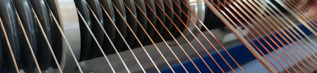
Enameled copper clad aluminum wire (ECCA) occupies a specific and bounded position in electronic magnetics. It is not a general substitute for copper, and its technical justification rests on a small number of measurable parameters: operating frequency, conductor diameter, copper volume fraction, and thermal class. Where those parameters fall inside a defined window, ECCA wire delivers a genuine reduction in mass and material cost at essentially unchanged electrical performance. Where they fall outside it, the substitution carries an electrical penalty that no amount of process control removes.
This article defines that window quantitatively, covers the application classes in which ECCA wire is established, and specifies the limits beyond which solid copper remains the correct engineering choice.
Why Electronic Applications Follow Different Selection Logic
Four Variables That Separate Electronics from Motor and Transformer Design
Conventional winding design for motors and power transformers is governed primarily by slot fill factor, permissible temperature rise, and material cost. Electronic magnetics introduces a fourth variable — operating frequency — and that variable reshapes the relative weight of the other three.
Frequency. Grid-frequency machines operate at 50 or 60 Hz. Switching power supplies operate between 20 kHz and 200 kHz, and wireless charging, server power conversion, and point-of-load modules operate in the megahertz range. Above roughly 100 kHz, the current distribution within a conductor is no longer uniform, and copper loss is no longer adequately described by DC resistance.
Conductor diameter. Motor stator windings typically use 0.5–2.0 mm conductors. Electronic transformers and inductors frequently use 0.1–0.5 mm, and voice coil, deflection coil, and precision instrument windings fall below 0.1 mm. The consequence is not simply a smaller cross-section: as the conductor diameter decreases, the absolute copper layer thickness decreases proportionally, which is what determines whether skin effect remains within the cladding.
Available volume. Motor and transformer designs are allocated a core, a housing, and a defined winding window. Electronic assemblies must fit a plastic enclosure measured in centimetres, sharing that volume with printed circuit boards, magnetic components, and thermal management structures. Every cubic millimetre consumed by winding must be taken from another function.
Regulatory scope. Motor insulation is rarely subject to component-level flame rating and material declaration requirements. Electronic assemblies form part of a finished-product certification chain, and a documentation gap in the material declaration chain invalidates the finished-product approval regardless of whether the conductor itself performs correctly.
The practical consequence is that ECCA wire does not directly replace copper in electronic design. It replaces copper within a bounded window defined by the first two variables.
Mass and Cost as the Governing Motivation
The recurring technical question in electronic magnetics is whether copper clad aluminum can be used in a switching power supply transformer winding. The answer is conditional, and it is determined by the data in the following sections rather than by a general statement about the material.
For a given DC resistance, ECCA wire offers approximately half the mass of pure copper. This follows directly from material properties: an ECCA conductor with 15% copper by volume has a density of 3.64 g/cm³ against 8.96 g/cm³ for annealed copper, and a DC resistance 1.45 times that of a copper conductor of equal diameter.
Material cost savings of 30% to 60% are reported in manufacturer technical data for equivalent-resistance designs. The realised figure depends on whether the winding design can be adjusted to accommodate the larger conductor diameter required for the same resistance, which is addressed in the slot fill factor discussion below.
Fundamental Parameters of ECCA in Electronic Design
Conductor Construction and Its Three Practical Consequences
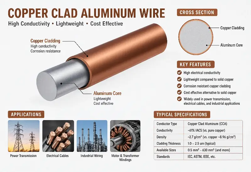
ECCA consists of an aluminium core, a continuous outer copper cladding, and an applied enamel coating. The cladding may be produced by electroplating or by metallurgical bonding; the latter produces a stronger interface but with a narrower processing window.
For electronic applications, the copper cladding carries three specific consequences.
Solderability. The outer surface is copper, so the oxide removal and pre-treatment steps otherwise required for aluminium conductors are eliminated. For electronics assembly lines this removes a dedicated cleaning or pre-dipping station and the associated handling of aluminium oxide residue.
Terminal connection. Winding leads are crimped or soldered to printed circuit boards or connectors. Because the outer layer is copper, conventional copper terminal and solder processes apply without modification.
High-frequency conduction. At elevated frequency, current concentrates at the conductor surface. Since the surface of ECCA is copper rather than aluminium, this determines the electrical behaviour of the material in high-frequency applications, and is the subject of the skin depth analysis that follows.
Copper Content, Resistivity, and Density
ASTM B566 covers bare round copper-clad aluminum wire and defines exactly four classes:
| Class | Nominal copper content | Temper | DC resistivity (Ω·mm²/m) | Density (g/cm³) |
|---|---|---|---|---|
| 10A | 10 volume % | Annealed | 0.02743 | 3.32 |
| 15A | 15 volume % | Annealed | 0.02676 | 3.63 |
| 10H | 10 volume % | Hard-drawn | 0.02743 | 3.32 |
| 15H | 15 volume % | Hard-drawn | 0.02676 | 3.63 |
The difference between the A and H suffixes is temper: annealed versus hard-drawn. The difference between the 10 and 15 prefixes is copper volume percentage.
GB/T 29197-2012 adds Class 20A and Class 20H at 18% to 22% copper by volume, with a DC resistivity of 0.02594 Ω·mm²/m.
Products carrying 30% or 40% copper content also exist commercially. These percentages fall outside every class defined in the two standards above. Any such product must be specified by explicit agreement of copper content and resistivity, with the applicable standard stated as ASTM B566 or GB/T 29197-2012.
Two clarifications on the terminology are required, because the two are frequently conflated in technical discussion:
- The resistivity ratio between aluminium and copper as pure metals is 1.58 (2.65 × 10⁻⁸ against 1.68 × 10⁻⁸ Ω·m).
- The DC resistance ratio of the finished ECCA conductor against a copper conductor of equal diameter is 1.45 at 15% copper by volume, 1.49 at 10%, and 1.42 at 20%.
The second figure is lower than the first because the copper cladding and the aluminium core conduct in parallel, and because the combined density falls well below that of copper.
Enamel System Selection for Electronics
Electronic applications place greater emphasis on two enamel attributes than electrical machine design does: solderability and thermal class.
UEW (polyurethane, Class 155) offers the highest solderability and is the most widely specified enamel in electronic winding. Solderable polyurethane magnet wire is designed for removal of the coating by a hot solder dip, with the coating stripping during the solder dwell rather than requiring a mechanical or chemical stripping operation. The melting range of the coating is typically in the 180–200 °C region, and the soldering temperature at the joint remains governed by the solder alloy and the thermal mass of the joint rather than by the coating alone. Flux remains part of a normal soldering process; a solderable enamel system removes the need for mechanical stripping, not the need for flux.
PEW (polyester, Class 155) provides higher thermal resistance and mechanical strength than UEW and is specified where post-soldering is not required. Polyester is the conventional base coat for self-adhesive wire, where a thermoplastic adhesive layer is applied beneath the outer enamel.
EIW and AIW (polyesterimide and polyamide-imide, Class 200 to 220) are specified for applications with elevated thermal requirements or flame retardance requirements. Although the formal rating is generally 220 °C, the softening breakdown temperature of polyamide-imide is typically in the 330–350 °C range, and the coating retains low internal stress under thermal shock above 200 °C.
The significant point for selection is that the enamel requirements differ by application class within electronics, and a single coating system is not appropriate across all of them.
Skin Depth: The Criterion That Determines Where ECCA Is Equivalent to Copper
Current Distribution in a Conductor
Under direct current, current density is uniform across the conductor cross-section. Under alternating current, the magnetic field induced within the conductor drives current toward the surface, and current density decays exponentially from that surface. The depth at which current density falls to 1/e (approximately 37%) of its surface value is the skin depth:
$$\delta = \sqrt{1 / (\pi f \mu \sigma)}$$
where f is frequency, μ is magnetic permeability (μ₀ for the non-magnetic conductor materials used here), and σ is electrical conductivity.
Using σ = 5.96 × 10⁷ S/m for copper and σ = 3.77 × 10⁷ S/m for aluminium:
| Frequency | Skin depth in copper | Skin depth in aluminium |
|---|---|---|
| 50 Hz | 9.22 mm | 11.59 mm |
| 100 kHz | 206 µm | 259 µm |
| 1 MHz | 65.2 µm | 82.0 µm |
| 5 MHz | 29.2 µm | 36.7 µm |
| 20 MHz | 14.6 µm | 18.3 µm |
| 1 GHz | 2.06 µm | 2.59 µm |
Two relationships follow directly. Skin depth varies inversely with the square root of frequency, so a tenfold increase in frequency reduces skin depth to approximately 1/√10 of its previous value. The aluminium skin depth exceeds the copper skin depth by a factor of 1.26, which is the square root of the conductivity ratio; it is not related to the resistivity ratio of 1.58.
Copper Layer Thickness in Round ECCA Conductor
For a round conductor of diameter d with copper volume fraction f_cu, the copper layer thickness is the difference between the outer radius and the aluminium core radius:
t_cu = (d / 2) − (d / 2)·√(1 − f_cu)
The distinction between copper layer thickness and the product d × f_cu is significant. The latter overstates the cladding thickness by roughly a factor of two for a round conductor, and an incorrect estimate of this value leads directly to an incorrect assessment of high-frequency suitability.
| Diameter | 10% Cu | 15% Cu | 20% Cu | 25% Cu |
|---|---|---|---|---|
| 0.10 mm | 2.57 µm | 3.90 µm | 5.28 µm | 6.70 µm |
| 0.20 mm | 5.13 µm | 7.80 µm | 10.56 µm | 13.40 µm |
| 0.30 mm | 7.70 µm | 11.71 µm | 15.84 µm | 20.10 µm |
| 0.40 mm | 10.26 µm | 15.61 µm | 21.11 µm | 26.79 µm |
| 0.50 mm | 12.83 µm | 19.51 µm | 26.39 µm | 33.49 µm |
The Frequency Criterion
Because the outer layer of ECCA is copper, current flows entirely within the copper cladding while the skin depth remains smaller than the cladding thickness. When skin depth exceeds cladding thickness, current penetrates the aluminium core, where resistivity is 1.58 times that of copper, and the conductor loses its copper-equivalent high-frequency behaviour.
Setting δ equal to t_cu gives the crossover frequency:
f_c = 1 / (π·μ₀·σ_cu·t_cu²)
| Diameter | 10% Cu | 15% Cu | 20% Cu | 25% Cu |
|---|---|---|---|---|
| 0.10 mm | 646 MHz | 279 MHz | 153 MHz | 94.7 MHz |
| 0.20 mm | 161 MHz | 69.8 MHz | 38.1 MHz | 23.7 MHz |
| 0.30 mm | 71.7 MHz | 31.0 MHz | 17.0 MHz | 10.5 MHz |
| 0.40 mm | 40.4 MHz | 17.4 MHz | 9.53 MHz | 5.92 MHz |
| 0.50 mm | 25.8 MHz | 11.2 MHz | 6.10 MHz | 3.79 MHz |
Above the crossover frequency, ECCA carries current in its copper cladding and behaves as a solid copper conductor of the same diameter. Below it, the aluminium core carries part of the current and the conductor presents a higher resistance than copper.
This corrects a widely repeated industry statement that ECCA transmission performance above 5 MHz is equivalent to pure copper. As the table above shows, that condition is met in round wire only at diameters of 0.5 mm and above combined with copper content of 25% or more. In the 0.1 mm to 0.3 mm range typical of switching power supply magnetics at 20–150 kHz, skin depth remains substantially larger than the copper layer thickness, and the conductor operates on its DC resistance characteristics with the associated increase in copper loss.
The consequence is that the relevant comparison at low switching frequencies is between the resistive loss of ECCA and the mass and cost savings it delivers, not an assumed equivalence with copper.
Applying the criterion to ECCA wire in practice:
At frequencies below 100 kHz with conductor diameters above 0.3 mm, skin depth greatly exceeds the copper layer thickness. Current penetrates the aluminium core, ECCA presents approximately 1.45 times the DC resistance of copper at equal diameter, and the conductor delivers weight and cost advantages only. The additional loss must be evaluated against the thermal design of the specific assembly.
At frequencies where skin depth approaches or falls below the copper layer thickness, which for 0.3 mm conductors at 15% copper requires operation above approximately 31 MHz, ECCA approaches the high-frequency behaviour of pure copper.
At frequencies in the tens of megahertz and above, copper loss in solid copper conductors is already substantial and conductor diameters are already small. The relative value of ECCA shifts toward cost and mass rather than electrical performance.
The criterion is therefore a combination of frequency and conductor diameter. Frequency alone does not determine suitability.
Switching Power Supplies and High-Frequency Transformers
Main and Isolation Transformers
This is the most established application of ECCA wire in the electronics industry.
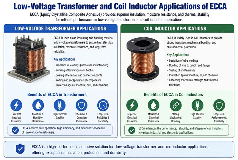
Copper clad aluminum wire is widely used in switching power supply, LED driver, and electronic ballast windings in the 20 kHz to 200 kHz band. Manufacturer technical data reports AC losses 8% to 12% higher than for pure copper conductors over this frequency range. The corresponding material cost reduction is 30% to 60%, with mass reduced by approximately 50%.
This trade is favourable where the assembly is constrained in both size and cost, which describes external power supplies, chargers, and adapter designs.
The loss figure is valid only at a specified frequency and conductor diameter. If operating frequency increases from 65 kHz to 150 kHz, or conductor diameter decreases from 0.4 mm to 0.25 mm, the 8% to 12% figure no longer applies and the assessment must be repeated against the skin depth criterion.
Two Constraints Specific to Electronics
Slot fill factor. The winding must fit within a small window, and slot fill factor directly determines achievable power density. The enamel cost of ECCA wire is identical to that of copper, but the copper cladding reduces the effective conducting cross-section for a given overall diameter. ECCA requires a larger overall diameter for a given resistance, and the resulting increase in winding volume must be absorbed within the slot fill factor limit.
Creepage distance and clearance. The high-voltage winding has mandatory creepage distance requirements. Flat ECCA is advantageous in this respect, since the inter-turn separation is controlled directly by the flat conductor thickness rather than by the winding geometry.
Power Inductors and PFC / Buck-Boost Coils
Flat Conductor as the Predominant Form
For high-frequency, high-current inductors in photovoltaic inverters, energy storage systems, and automotive on-board chargers, the flat conductor is the predominant form. Three factors support this configuration:
1. Winding window utilisation. Flat conductor packing achieves a higher effective conductor cross-section within a given window than round conductor. 2. Eddy current reduction. The high width-to-thickness ratio reduces the effective current path length within an individual conductor cross-section. 3. Thermal interface. Flat conductor seats directly against the baseplate, improving heat transfer from the winding.
The third factor is frequently underweighted in high-power inductor design, where the thermal resistance between winding and baseplate can contribute more to total temperature rise than winding loss itself.
Self-Adhesive Wire
Self-adhesive wire is established in electronic winding. 0.21 mm self-adhesive polyester copper clad aluminum magnet wire at 25% copper content is a standardised product, available with UL, QC 080000, and IATF 16949 approvals.
The construction places a thermoplastic adhesive layer between the enamel and the conductor. After winding, the assembly is heated to 130–150 °C, at which temperature the adhesive softens and the wound layers bond into a single body. The result is the elimination of varnish impregnation and bobbin retention, and the coil leaves the winding machine in finished form.
In high-volume electronic production, the reduction in process steps typically outweighs the material cost saving.
Interface Degradation at Terminations
The copper cladding of flat ECCA wire is subject to cracking and delamination at crimp points, bend points, and lead-out transitions. In high-frequency, high-current applications, an increase in contact resistance at such a location produces localised heating that can exceed the savings realised elsewhere in the design.
Three controls apply:
- Lead-outs require a transition to solid copper, either by soldering or by a copper terminal designed for the clad conductor.
- Winding tension must be controlled so that the copper cladding is not fractured during compaction.
- Finished parts require tensile and peel testing in addition to visual inspection.
Voice Coils, Deflection Coils, and Precision Signal Windings
Voice Coils
Voice coils in loudspeakers, headphones, and in-ear monitors represent the application in which ECCA wire delivers the clearest physical benefit.
A voice coil is the load on the moving diaphragm, and transient response is governed directly by moving mass. Reducing voice coil mass increases acceleration and improves both startup and transient behaviour.
The electrical situation differs from that of power applications. Voice coil current operates across the audio band, from tens of hertz to 20 kHz. At 20 kHz the skin depth in copper is 3.3 mm, which exceeds any practical voice coil conductor diameter by more than an order of magnitude, so current density remains effectively uniform and the conductor operates on its DC resistance. The 1.45 resistance ratio against copper is therefore a real penalty rather than a negligible one.
The decision rests on mass rather than on resistance. Voice coils are wound with a small cross-section and a large number of turns, and the reduction in moving mass is the dominant consideration for acoustic performance.
Patent literature describes mobile phone and smartphone speaker voice coils using very fine magnet wire at 0.1 mm, 0.07 mm, and 0.05 mm, with a lower limit of approximately 0.01 mm.
Deflection Coils and Precision Instruments
The signal winding requirement in display deflection coils and precision instruments follows the same logic. Moving mass is reduced while the resistance requirement for signal transfer is less restrictive than in a power winding.
The common constraint in both is available volume. A deflection coil must be accommodated within the space available inside a tube or panel assembly, and the winding must fill that space. Reduction in conductor mass translates directly into additional design latitude.
Conductor diameters at or below 0.1 mm are used in such applications.
Where ECCA Is Normally Excluded
ECCA is normally excluded from signal and precision instrumentation windings.
The determining factor is the interface rather than the cladding. ECCA contains a metallurgical bond between two dissimilar metals, and the bond exhibits a lower strength than a single-metal conductor. Long-term parameter stability under combined thermal cycling and humidity cycling introduces an additional variable into signal integrity. Solid copper introduces no such variable, and the cost of eliminating it is not justified.
Connectors, Relays, and Small Precision Motors
Relay and Solenoid Coils
Relay coils and solenoid valve coils operate at low current and low frequency. Neither the high-frequency advantage nor the mass advantage of ECCA applies, because the winding mass is negligible in both cases. Substitution is not normally justified on technical grounds.
High-current relays and contactors represent a partial exception, where copper mass in the coil and contacts is a genuine consideration. Mixed-metal assemblies in which a clad conductor interfaces with solid copper contacts require evaluation of the interface itself.
Connectors and Cables
Connectivity forms a separate application segment within the product range. Coaxial trunk cables for CATV installation, and specialised audio and power leads, fall into this category.
The determining requirements in this segment are surface appearance and solderability. The copper-coloured surface and copper solderability of ECCA wire are the minimum acceptable specification. Solid aluminium wire has no viable position in this segment, since both appearance and the joining process would require modification.
Micro Motors and Small Automotive Motors
Air-conditioning indoor unit fan motors, refrigerator fan motors, washing machine drain pump motors, and power tool motors are established ECCA wire applications, for reasons distinct from those applying to industrial motors:
- Winding mass contributes directly to overall unit mass and handling feel.
- Production volumes are high and material cost sensitivity is correspondingly high.
- Operating frequencies of 50 Hz, or a few hundred hertz under variable frequency drive, leave skin effect negligible.
The same reasoning applies to windscreen wiper motors, window lift motors, cabin fan motors, and electric power steering assistance motors.
Automotive applications carry an additional requirement. The long-term bond strength of the copper-aluminium interface under repeated cycling between −40 °C and 150 °C must be verified. This verification is a qualification requirement and cannot be substituted with production inspection.
Enamel Coating and Compliance: Two Common Errors
UL 94 Is Not UL Certification
This is the most frequent misapplication of certification terminology in electronic procurement.
UL 94 is a flammability classification standard for plastic materials. It grades materials as HB, V-2, V-1, V-0, 5VB, and 5VA according to flame behaviour, dripping, and ignition of a specified cotton substrate at a defined specimen thickness. The V-0, V-1, and V-2 test methods correspond broadly to the IEC 60695 series, but the acceptance criteria and specimen thickness requirements are not identical, and the two systems are not interchangeable.
UL certification applies to a finished product or component, assessed against a defined safety standard.
The two are therefore distinct, and the relationship is directional: a material meeting the UL 94 V-0 classification does not constitute a product holding UL certification, while a product applying for UL certification is generally required to use materials that meet the corresponding UL 94 rating.
Electronic equipment typically requires both magnet wire listed under the applicable UL category, such as the UL 758 series, and certification of the finished device. These are separate requirements and must be tracked separately.
A further procurement point applies: a UL listing for one product from a given manufacturer does not extend automatically to other products. Changes to material specification, enamel system, or production location may each require the listing to be reconfirmed.
RoHS Compliance Does Not Complete CE Marking
RoHS is a substance restriction requirement within the CE framework. It is not a CE marking and does not produce one.
RoHS restricts ten substances: lead, cadmium, mercury, hexavalent chromium, and the four phthalates DEHP, BBP, DBP, and DIBP. Testing is performed to the IEC 62321 series, corresponding to the GB/T 39560 series in China. REACH SVHC obligations apply in addition, and the candidate list is updated periodically, requiring assessment against the list in force at the time of declaration.
Market access to the EU additionally requires conformity with the Low Voltage Directive, EMC requirements, and the applicable product safety standards, together with compilation of a technical file, issue of the Declaration of Conformity, and application of the CE marking.
For magnet wire suppliers this means that a general statement of RoHS compliance is insufficient. The supporting documentation must be a declaration of conformity specific to grade, specification, and production lot.
Halogen-Free Requirements
Some electronic customers specify halogen-free products, restricting the content of chlorine, bromine, and related elements. Certain polyester enamel systems and flame retardant formulations introduce halogen-containing components. Where a halogen-free specification is required, the enamel system must be selected and the declaration confirmed during the design phase, before qualification begins.
Where ECCA Is Not the Correct Choice
Low-Frequency, High-Current Conductors
In a 50 Hz power transformer or a several-thousand-ampere busbar, skin depth is on the order of millimetres and the great majority of the conductor cross-section is conducting. In this regime, the copper cladding offers no benefit, ECCA presents approximately 1.45 times the resistance of copper at equal diameter, and interface bond strength becomes an additional failure mode.
Where weight reduction is the objective in such applications, flat copper busbars, aluminium winding rather than clad conductor, or a revision of the magnetic circuit design are the appropriate measures.
Military, Aerospace, and Medical Applications
Failure mode analysis governs the selection in these areas. ECCA introduces a failure path that solid copper does not have: delamination of the copper cladding.
Where single-point failure is not acceptable, the interface between two dissimilar metals represents a structural difference that cannot be eliminated by raising inspection frequency. Solid copper remains the correct answer in this classification.
Screw Terminal and Crimped Connections
Where a winding lead is terminated in a screw terminal or a crimp contact, the terminal is pressed into the conductor. Deformation of solid copper under pressure is deformation of a single material. If the copper cladding of ECCA fractures under the same load, a localised resistive hot spot forms, which is of particular consequence in high-frequency, high-current circuits.
Three approaches are available: a solid copper transition lead at the lead-out, a terminal designed for clad aluminum conductor, or soldering of the lead-out. These are engineering options rather than obstacles, but they should be specified explicitly rather than assumed.
Very Low-Power Signal Windings
In relay coils and low-level signal instruments, current is small, turn count is high, and conductor is fine. ECCA offers no material mass advantage in this class, while retaining the resistance disadvantage and the interface variable. The cost saving is generally insufficient to offset the additional qualification effort.
Applications Requiring a Continuous Homogeneous Conductor Section
High-frequency high-current interconnects, direct-current busbars, and precision resistive elements require a continuous and homogeneous metal cross-section. In these applications the clad structure of ECCA is a liability rather than an advantage.
Selection Method and Technical Agreement Clauses
A Five-Step Selection Method
Step 1 — Establish the operating frequency. At 50 or 60 Hz, skin effect is not a consideration and the evaluation proceeds directly to cost. Above 100 kHz, proceed to Step 2.
Step 2 — Calculate skin depth. Apply δ = √(1/(πfμσ)) with σ = 5.96 × 10⁷ S/m for the copper layer.
Step 3 — Calculate copper layer thickness. For round conductor, apply t_cu = (d/2) − (d/2)·√(1 − f_cu) using the specified copper volume fraction. Compare the result against the skin depth.
- Skin depth greatly exceeds t_cu: current penetrates the aluminium core, ECCA presents increased resistance, and the selection proceeds on mass and cost with the resistive penalty quantified.
- Skin depth approximately equals t_cu: the crossover condition, at which current is substantially confined to the copper layer.
- Skin depth below t_cu: current is confined to the copper cladding and the conductor behaves as solid copper.
Step 4 — Specify the conductor class. ASTM B566 Class 10A, 15A, 10H, or 15H; GB/T 29197-2012 Class 20A or 20H; or an explicitly agreed copper content outside those classifications.
Step 5 — Specify the enamel system. UEW where post-soldering is required, PEW where thermal resistance and mechanical strength govern, EIW or AIW for Class 200 and 220 duty. Confirm whether a self-adhesive construction is required.
Clauses Required in the Technical Agreement
Where these fields are left undefined, incoming inspection disputes are likely. Seven clauses should be fixed:
1. Copper content and measurement method. Volume basis or mass basis must be stated. Chemical dissolution with gravimetric determination provides the most direct arbitration, metallographic sectioning serves as a reference method, and eddy current measurement is appropriate for rapid in-line thickness verification. 2. Copper layer thickness and uniformity. Nominal value with tolerance, with particular attention to the minimum value at the smallest conductor diameter in the range. 3. DC resistivity. Limit at 20 °C, referenced to ASTM B566 or GB/T 29197-2012. 4. Interface bond strength. Reverse bending adhesion test conditions, including bend angle, mandrel diameter, and number of bends. 5. Enamel grade and pinholes. Thermal class, coating thickness grade, and pinhole test criteria. 6. Applicable conductor diameter range. Not all diameters are produced in all classes, and this must be stated. 7. Material compliance declarations. RoHS, REACH, and halogen-free declarations referenced to a specific grade and production lot.
Technical Agreement Content
The following represents the information an engineering team specifies when ECCA wire is introduced into an electronic product specification.
Conductor construction. Copper volume fraction, stated as volume or mass with the arbitration method defined. Chemical dissolution with gravimetric determination is the most direct method; the metallurgical method serves as reference; the eddy current method suits rapid in-line thickness measurement.
Electrical and thermal data. DC resistance per unit length, maximum resistance after thermal ageing, conductor diameter and tolerance, and applicable thermal class.
Enamel system. Coating type, grade level, solderability requirement, and where applicable the soldering conditions and permitted residual soldering time.
Surface and geometry. Round or flat conductor, flat conductor thickness and width tolerances, and surface quality requirements for the coating.
Compliance and delivery. RoHS, REACH, and halogen-free declarations referenced to a specific grade and lot.
Conclusion
Whether ECCA enameled wire is suitable for a given electronic design is determined by four specified values: operating frequency, conductor diameter, copper volume fraction, and required thermal class. The relationship between them is fixed by the skin depth criterion.
Frequency determines skin depth, and skin depth determines whether the copper layer is thick enough to carry the current. Below approximately 100 kHz with conductors above 0.3 mm, ECCA is a mass and cost measure and the resistive penalty must be quantified against the thermal design. Above the crossover frequency for the selected diameter and copper content, current is confined to the copper cladding and the conductor approaches solid copper behaviour.
The enamel system determines whether the downstream soldering and assembly processes can be maintained without line modification. UEW is specified where post-soldering is required, PEW where thermal and mechanical performance govern, and EIW or AIW where Class 200 or 220 duty applies.
The reliability classification determines whether the copper-aluminium interface is an acceptable addition to the failure modes. ECCA wire is appropriate for consumer electronics, power modules, connectivity products, and small automotive motors. Solid copper remains the specified conductor for military, aerospace, and medical applications, for direct-current busbars, and for screw-terminal and crimped terminations.
Where the four values are fixed and the corresponding clauses are written into the technical agreement, the material question is resolved.
The skin depth values in this article are derived from δ = √(1/(πfμσ)) with σ = 5.96 × 10⁷ S/m for copper and σ = 3.77 × 10⁷ S/m for aluminium. Loss comparison and cost range data are taken from publicly available manufacturer technical documentation and industry calculation, and should be confirmed against measured values in the specific design. The class definitions, copper content, and resistivity values for ASTM B566 and GB/T 29197-2012 are reproduced from those standards.