


I. Introduction: The Rise of High-Speed Motors and Insulation Challenges
1.1 Definition and Classification of High-Speed
Motors In the industry, motors are typically classified into four categories based on their rotational speed: low-speed motors (< 3,000 rpm), medium-speed motors (3,000–10,000 rpm), high-speed motors (10,000–50,000 rpm), and ultra-high-speed motors (> 50,000 rpm). High-speed motors mostly employ permanent magnet synchronous (PMSM) or induction asynchronous (IM) structures. In some applications (turbomolecular pumps, micro-turbine generators), sensorless high-speed brushless DC (BLDC) or switched reluctance (SRM) structures are used. In terms of power range, they cover everything from watt-level micro-motors (several hundred watts in turbomolecular pumps) to megawatt-level large motors (high-speed flywheel energy storage, gas turbine starter motors).
1.2 Four Core Advantages of High-Speed
Motors The fundamental reason for the resurgence of high-speed motors in the Industry 4.0 era is their four core advantages. First, high power density—Power is directly proportional to speed; a 30,000 rpm motor can be 5–10 times smaller and 3–8 times lighter than a 1,500 rpm motor of the same power. Second, high efficiency—High-speed direct drive eliminates the need for a reduction gearbox (gearbox efficiency loss of 5–15%), increasing system efficiency by 5–15%. Third, fast dynamic response—Low rotor moment of inertia significantly shortens acceleration/deceleration time constants, making it suitable for servo applications with frequent start-stop cycles. Fourth, miniaturized supporting equipment—The impeller diameter of high-speed centrifugal pumps, compressors, and blowers is inversely proportional to speed, enabling overall equipment miniaturization.
1.3 Five Challenges High-Speed
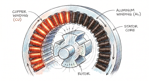
Motors Present to Insulation Systems The characteristics of high-speed operation bring five challenges that are almost unheard of in conventional industrial motors to motor insulation systems. (1) High-frequency electromagnetic field—10,000 rpm + few pole pairs → Electrical frequency can reach above 1,000 Hz. Skin effect and proximity effect cause the skin depth to drop to below 1 mm. The effective cross-sectional area utilization of conventional round copper wire decreases by 30–50%, and Litz wire or rectangular flat wire must be used. (2) High temperature—The eddy current loss and wind friction loss of the rotor core of high-speed motor increase to the power of 1.5–2 of the rotational speed. The hot spot temperature can reach 180–240°C, far exceeding the ordinary H-class 180°C. (3) High mechanical stress (centrifugal force)—The winding ends are subjected to a centrifugal force of 30,000+ g (g=9.8 m/s²). Ordinary enameled wire + impregnated varnish end bindings will “fall apart” within minutes. A combination of FIW fully insulated defect-free enameled wire + end bushings + vacuum pressure impregnation (VPI) must be used. (4) Partial discharge (PD)—The du/dt of the inverter’s PWM power supply is as high as 5–10 kV/μs. Uneven voltage distribution between winding turns can easily cause corona breakdown, shortening the life of ordinary enameled wire by 5–10 times. (5) Difficult heat dissipation—High-speed motors mostly use closed air cooling or water jacket cooling. The windings are embedded in narrow stator slots, making it difficult for heat to be conducted away. These five challenges together determine that the insulation design of high-speed motors must be “differentiated”—the insulation scheme of ordinary industrial motors cannot be simply copied. ** —
II. Key Performance Indicators of enameled wire for High-Speed Motors
2.1 Thermal Class: H-class (180°C) / C-class (200°C) / C+-class (220°C)
The thermal class of high-speed motors far exceeds that of ordinary industrial motors. Conventional H-class (180°C) enameled wire (such as a single-coated PEI polyimide layer) is insufficient for high-speed motors above 30,000 rpm. The mainstream solutions are C-class (200°C, PEI+PAI dual-coating) or C+-class (220°C, PI polyimide coating). In extreme scenarios with hotspot temperatures of 220–240°C, such as eVTOL propulsion motors and micro-turbine generators, a 240-class solution (PI/PAI + special primer) is required. The thermal class is positively correlated with rotational speed—the higher the speed, the higher the hotspot temperature, and the more stringent the thermal class requirements. **
2.2 High-Frequency Characteristics: Litz Wire and Rectangular Flat Wire
** High-frequency characteristics are the most crucial indicator of insulation in high-speed motors. The skin depth formula is δ = √(ρ/(π·f·μ)), where ρ is resistivity, f is frequency, and μ is permeability. At 1,000 Hz / 1.5 T, the skin depth of copper is approximately 2.1 mm; however, at 10,000 Hz (the typical electrical frequency of high-speed permanent magnet motors), the skin depth drops to 0.66 mm. This means that a conventional 1.0 mm diameter round copper wire is almost non-conductive in the central region at 10,000 Hz, with a cross-sectional area utilization rate of only 30–40%. There are three solutions: First, Litz wire – multiple strands of fine enameled wire with a diameter of 0.05–0.20 mm are twisted together (typically 50–200 strands), each strand is individually insulated, and the skin effect is “cut” into the extremely small diameter of each strand, reducing losses by 50–80%, making it the “main force” of high-speed motor windings; Second, flat wire (Hairpin) – flat copper wire with a rectangular cross-section replaces round wire. Rectangular cross-sectional area utilization is 20–30% higher than that of round wire, making it the mainstream solution for new energy vehicle drive motors (800V high voltage, 6,000–20,000 rpm), and it has recently begun to penetrate into high-speed electric spindles of 30,000+ rpm; Third, copper foil winding – extremely thin copper foil (thickness 0.1–0.3 mm) is wound, providing excellent heat dissipation, and is mainly used in high-frequency transformers and small high-speed motors.
2.3 Centrifugal Force Resistance: FIW Fully Insulated, Defect-Free enameled wire
Centrifugal force resistance is the “lifeline” for high-speed motor windings. Taking a 30,000 rpm high-speed permanent magnet motor with a winding end diameter of 80 mm as an example, the centrifugal acceleration of the copper wire at the winding end is approximately 80,000 m/s² ≈ 8,000 g. Conventional enameled wire + varnish-impregnated end structures are at risk of “scattering” at 1,000 g, and at 8,000 g, they disintegrate instantly. FIW (Fully Insulated Wire) was developed to meet this need—it is a special type of enameled wire defined by IEC 60317-0-1. Through three or more layers of polyester imide coating (levels 4, 6, and 8), it achieves a breakdown voltage of 6–12 kV (compared to 4–6 kV for ordinary enameled wire), eliminating the need for traditional components such as insulating sleeves, end binding tapes, and interphase insulation paper. FIW has a dielectric loss tangent tan δ ≤ 0.02 at 1000 Hz, which is 1/3 that of ordinary enameled wire. Its core advantages are “high breakdown voltage + zero defects,” ensuring no inter-turn short circuits occur under centrifugal forces of 30,000+ g. LNPU’s FIW product line offers three levels: 4 (4 layers of enamel), 6 (6 layers of enamel), and 8 (8 layers of enamel), with nominal conductor diameters ranging from 0.020 to 1.000 mm, covering a full range of applications from micro motors to large industrial high-speed motors.
2.4 Anti-PD (Partial Discharge): Corona-resistant enamel coating
. During PWM switching, high-speed motors powered by frequency converters experience inter-turn voltage spikes of 5–10 kV/μs in the windings. Over long-term operation, ordinary enamel coatings can be corroded by corona discharge, shortening their lifespan by 5–10 times. Corona-resistant enamel coating is a key technology for high-speed motor windings. The principle is to add nano-alumina (Al₂O₃) or titanium dioxide (TiO₂) fillers to a regular PI (polyimide) enamel coating. The nanoparticles form a “barrier layer” on the enamel coating surface, dispersing the PD charge throughout the entire enamel coating rather than causing localized breakdown. The lifetime specification for the corona-resistant enamel coating is: at 200°C / 50 Hz / 6 kV/mm, the PD lifetime is ≥ 1,000 hours (compared to only 100–200 hours for regular PI enamel coatings). Standards such as IEEE 1776 and IEC 60034-18-41 specify the test methods for corona-resistant enamel coatings. LNPU high-speed motor-specific corona resistantenameled wire utilizes a PI + nano Al₂O₃ composite enamel coating, passing the 1,000-hour PD test according to IEC 60034-18-41 standard.
2.5 End-Winding Bracing and Slot Liner
End-Winding bracing for high-speed motors is just as critical as slot lining. End-Winding typically uses polyester fiber tubing, glass fiber tubing, Kapton polyimide film tape, or Nomex aramid paper, pre-bound before VPI (vacuum pressure impregnation), followed by impregnation and curing with a solvent-free impregnating varnish (such as epoxy resin or silicone resin). For slot insulation, NHN composite insulation paper (Nomex + polyester film + Nomex three-layer composite), DMD composite paper (polyester film + polyester fiber), or NMN composite paper are used. NHN slot insulation is recommended for high-speed motors because Nomex aramid paper has a temperature resistance of 220°C, high mechanical strength, and good compatibility with H/C grade enamel coating. Regarding VPI technology, vacuum pressure impregnation (VPI) allows the impregnating varnish to penetrate between each enameled wire inside the winding, significantly improving heat dissipation efficiency (10–30%) and electrical strength (30–50%). —
III. Typical Application 1: Motorized Spindle
3.1 Operating Characteristics of Electric Spindles
Electric spindles are the most typical application of high-speed motors—integrating the motor and machine tool spindle into one unit, with a speed range of 10,000–100,000 rpm (up to 150,000 rpm in high-end PCB drilling machines and CNC engraving and milling machines), and a power range of 0.5–50 kW. The core components of an electric spindle include a high-speed permanent magnet synchronous motor, precision ceramic bearings (or magnetic levitation bearings), a cooling system, and an HMI encoder. The insulation requirements for electric spindles focus on three points: high temperature resistance (H/C grade), centrifugal force resistance (FIW + end binding), and high-frequency resistance (Litz wire). LNPU provides a complete insulation solution for electric spindles—Litz wire (50–200 strands/0.05 mm) + FIW enameled wire + Kapton end straps + VPI impregnation varnish, all conforming to IEC 60034 / GB/T 755 standards.
3.2 Special Insulation Requirements for High-Speed
Electric Spindles Compared to ordinary electric spindles, ultra-high-speed electric spindles at 50,000+ rpm have four special requirements. First, higher temperature resistance—winding friction loss is directly proportional to the rotational speed³, and the winding hot spot temperature of a 60,000 rpm electric spindle is 20–30°C higher than that of a 15,000 rpm spindle. Second, stronger resistance to centrifugal force—the centrifugal force at the winding ends reaches 30,000 g, making FIW Class 6/8 essential. Third, Lower Vibration—Winding dynamic balance requires within ±2 g·mm, necessitating an enamel coating thickness tolerance of ±0.005 mm (compared to ±0.01 mm for ordinary motors). Fourth, Lower Noise—Electromagnetic noise is proportional to the 1.5th power of the rotational speed; a 60,000 rpm electric spindle can reach 75 dB noise, and the insulation layer cannot amplify vibration. LNPU FIW 8-level enameled wire is specifically designed for ultra-high-speed electric spindles—8 layers of polyester imide enamel coating, breakdown voltage of 10 kV, enamel coating thickness tolerance of ±0.005 mm, and 100% online pinhole detection.
3.3 Ultimate Insulation for PCB Drilling Spindles
PCB drilling spindles are the “special forces” of electric spindles—speeding up to 150,000–300,000 rpm (miniature high-speed BLDC), with power ranging from 0.2–1.5 kW. At these extremely high speeds, centrifugal force can reach 200,000 g (200,000 times the acceleration due to gravity), rendering ordinary enameled wire completely ineffective. PCB drilling spindles commonly employ a winding-free structure—a permanent magnet rotor (sintered NdFeB N52SH) + PCB stator (flexible circuit board coil). The flexible circuit board coil uses 2 oz thick copper foil (70 μm) + PI polyimide insulation layer, with a single layer thickness of only 0.1–0.3 mm, capable of withstanding centrifugal force of 300,000+ rpm. LNPU offers ultra-thin copper foil enameled wire (0.05–0.30 mm thick), suitable for extremely high-speed applications such as PCB drilling spindles and medical micro-motors. —
IV. Typical Application Two: Turbo Molecular Pump
4.1 Operating Characteristics of Turbomolecular Pumps
Turbomolecular pumps (TMPs) are core equipment for achieving high vacuum (10⁻⁸ Pa level) in fields such as semiconductor devices, vacuum coating, and particle accelerators. Their high-speed motor operates at speeds of 21,000–100,000 rpm and is directly connected to the turbine blades coaxially. The Pfeiffer HiPace 700 is an industry benchmark—its 700 L/s pumping speed molecular pump uses a high-speed permanent magnet synchronous motor, operating at 21,000–60,000 rpm, UL/CSA certified, IP54 protected, and integrated with air cooling. The motor of a turbomolecular pump must meet three major requirements: low noise (no vacuum contamination), high reliability (24/7 continuous operation), and maintenance-free (ceramic bearing life of 5+ years). Regarding insulation, the turbomolecular pump motor uses Class H (180°C) FIW (enameled wire) + end binding + VPI impregnation varnish—because organic matter (vacuum contamination) cannot be released into the vacuum chamber of the turbomolecular pump, the insulation layer must be “low outgassing”.
4.2 Special Insulation Requirements for Vacuum Environments
** The “low outgassing” requirement for insulation materials in a vacuum environment is not present in ordinary motors—small molecules (such as solvents and uncrosslinked monomers) in insulating varnishes, impregnation varnishes, and slotted insulating paper will slowly release in a vacuum, contaminating the vacuum chamber and causing a decrease in vacuum level. LNPU provides “low outgassing FIW” for turbomolecular pumps—through a 200°C/24-hour vacuum baking pretreatment, the small molecule volatiles in the enamel coating are reduced to <0.1%, meeting the ASTM E595 standard (NASA low outgassing material standard). Low-emission FIW + low-emission impregnation varnish + ceramic bearings** is the “golden combination” for turbomolecular pump motors.
4.3 Key Considerations for Insulation Selection for Turbomolecular Pumps
Insulation selection for turbomolecular pumps should focus on five points. First, FIW Class—FIW Class 4 is optional below 30,000 rpm, and FIW Class 6/8 is required above 30,000 rpm. Second, Low Emission—enamel coating TML (Total Mass Loss) ≤ 1%, CVCM (Collected Volatile Condensable Materials) ≤ 0.1%. Third, Thermal Stability—200°C / 100,000 h life (IEC 60034-18-31 standard). Fourth, Chemical Inertness—Resistant to vacuum pump oil (such as Fomblin perfluoropolyether oil). Fifth, Flexibility—Can be wound with small diameter (≤ 10 mm) stator slots without cracking. LNPU turbomolecular pump-specific FIW (enameled wire) is NASA ASTM E595 certified, with CVCM < 0.05%. —
V. Typical Application Three: High-Speed Centrifugal Compressors and Blowers
5.1 Operating Characteristics of High-Speed
Centrifugal Compressors High-speed centrifugal compressors (HVAC, fuel cell air compressors, industrial gas compressors) and high-speed centrifugal blowers (sewage treatment, power plant desulfurization aeration) are the “industrial heart” of high-speed motors—speed 10,000–60,000 rpm, power 50–500 kW, integrating permanent magnet synchronous motor + centrifugal impeller + frequency converter. Compared to electric spindles and turbomolecular pumps, high-speed centrifugal compressors have higher power, longer continuous operating time (8,000+ hours per year), and higher reliability requirements. Insulation typically uses H/C class FIW (enameled wire) + rectangular flat wire (Hairpin) + NHN groove insulation + VPI impregnation varnish. LNPU high-speed centrifugal compressor-specific enameled wire is available in 0.5–2.0 mm diameter round wire and 2.0–10.0 mm wide rectangular flat wire, fully covering the 50–500 kW power range.
5.2 Special Requirements for Fuel Cell Air Compressors
The FC Air Compressor is a key component of hydrogen fuel cell vehicles—providing high-pressure air (pressure 2.5–3.5 bar) to the fuel cell stack, operating at 30,000–100,000 rpm, with a power output of 30–150 kW. Special requirements for fuel cell air compressors include: (1) Explosion-proof—no sparks can be generated in a hydrogen environment; the insulation layer must withstand corona breakdown testing; (2) High efficiency—the efficiency of the fuel cell system is 50–60%, and a 1% decrease in air compressor efficiency directly affects the driving range; (3) Fast response—automotive operating conditions are highly variable, and the air compressor’s response time from 0–100% speed must be ≤ 2 seconds. For insulation, H-class (180°C) FIW 6 + rectangular flat wire + vacuum pressure impregnation (VPI) is selected. The LNPU fuel cell-specific enameled wire has passed IP67 explosion-proof certification and IEC 60079 explosion-proof standard.**
5.3 High-Reliability Insulation for Industrial Blowers
Industrial blowers (used in wastewater treatment aeration, power plant desulfurization, and aquaculture oxygenation) operate in harsh environments—high humidity (95% RH), high dust levels (PM2.5 100–500 μg/m³), and corrosive gases (H₂S, NH₃, Cl₂). The insulation solution must use H/C grade fiberglass-coated enameled wire with end binding and VPI impregnation. LNPU industrial blower-specific fiberglass-coated enameled flat copper wire (H grade 180°C / C grade 200°C) is the preferred choice—the fiberglass layer provides mechanical protection, the impregnation varnish provides chemical corrosion resistance, and the VPI process provides overall sealing. This solution has been operating in the wastewater treatment industry for over 10 years without any failures. —
VI. Typical Application Four: High-Speed Flywheel Energy Storage (FESS)
6.1 Operating Characteristics of Flywheel Energy Storage System
Flywheel Energy Storage System (FESS) utilizes a high-speed rotating flywheel to store kinetic energy—speed 10,000–50,000 rpm, energy density 100–200 Wh/kg (far exceeding the 150–250 Wh/kg of lithium batteries), cycle life 1,000,000+ cycles (lithium batteries 3,000–5,000 cycles). It is an “ideal energy storage solution” for rail transit braking energy recovery, UPS uninterruptible power supplies, and microgrid frequency regulation. The core component of flywheel energy storage is a high-speed permanent magnet synchronous motor + carbon fiber composite flywheel within a vacuum chamber—the motor acts as both a drive motor (converting electrical energy into kinetic energy during charging) and a generator motor (converting kinetic energy into electrical energy during discharging). Insulation requirements include H/C grade (high temperature resistance) (due to frictional heat from the flywheel surface + motor losses), low gas release (within a vacuum chamber), and long lifespan (10+ years of cycles).
6.2 Special Challenges of Insulation for Flywheel Energy Storage
Flywheel energy storage insulation faces three major special challenges. First, frequent start-stop cycles—50–200 charge-discharge cycles per day, the insulation layer endures repeated thermal cycling and mechanical vibration, significantly shortening the lifespan of ordinary enamel coatings based on the number of cycles. Second, vacuum environment—the motor is placed in a 10⁻² Pa vacuum chamber, requiring low gas release from the enamel coating, similar to that of a turbomolecular pump. Third, long lifespan—a service life of over 10 years, with a total winding cycle count > 500,000, requires the enamel coating to maintain performance under multiple thermal-mechanical-electrochemical stresses. LNPU FESS Dedicated Enameled Wire utilizes a PI (polyimide) enamel coating + 200°C thermal stability + vacuum low-release-gas formula, capable of passing 50,000 accelerated aging cycles.
6.3 Key Selection Points for Motor Insulation in Flywheel Energy Storage
The selection of motor insulation for flywheel energy storage should focus on five points: First, PI enamel coating (200°C+)—resistant to frequent thermal cycling; the temperature resistance index of PI enamel coating is 20°C higher than PEI, extending its lifespan by 5–10 times. Second, Fiberglass Covering—enhanced mechanical strength and centrifugal force protection. Third, End Binding—high-strength fiberglass tubing or Kapton straps + VPI impregnation. Fourth, Low-Release-Gas Enameled Wire—TML < 0.5%, CVCM < 0.05%. Fifth, NEMA MW 1000 §3.58 Accelerated Thermal Aging Test—Breakdown voltage retention rate ≥ 80% after thermal aging at 200°C / 168 h. LNPU FESS Dedicated enameled wire fully meets the above five points and has been mass-produced and applied in multiple FESS projects in China. —
VII. Typical Application Five: eVTOL/UAV Propulsion Motor
7.1 eVTOL Propulsion Motor Operating Characteristics
eVTOL (Electric Vertical Take-Off and Landing) Urban Air Mobility represents the latest cutting-edge application of high-speed motors—companies such as Joby Aviation, Archer Aviation, EHang, and XPeng Aerospace have launched eVTOL aircraft, with propulsion motor speeds of 8,000–25,000 rpm and power of 200–800 kW (single unit). eVTOL propulsion motor insulation requirements “aviation grade”—(1) Extremely lightweight—1 kg weight reduction means 1 minute more flight time;(2) High power density—> 10 kW/kg;(3) Aviation grade reliability—10⁻⁹ failure rate (DO-160G standard);(4) Resistance to high altitude and low pressure—operating altitude 1000–3000 m, insulation layer must withstand low pressure without breakdown;(5) Low temperature resistance—starting at -40°C at high altitude, enamel coating must not crack.
7.2 Key points for eVTOL motor insulation selection
** The insulation selection for eVTOL motors should focus on five points. First, PI enamel coating or Class 240—temperature resistance of 220–240°C to meet high power density. Second, Rectangular Flat Wire (Hairpin) – 800V high-voltage architecture, slot fill factor 70%+, is the current mainstream for eVTOL propulsion motors. Third, Corona Resistant (enamel coating) – PWM du/dt up to 10 kV/μs requires PI + nano-Al₂O₃ for PD resistance. Fourth, Low-Voltage Breakdown Strength – At an altitude of 3000 m and an air density of 0.7 kg/m³, the breakdown voltage drops by 20–30%, requiring a margin in the design. Fifth, Aerospace-Grade Certification** – DO-160G / RTCA / CCAR-21 certification. The LNPU eVTOL-specific rectangular flat wire (enameled wire) uses PI + nano-Al₂O₃ enamel coating and passes the RTCA DO-160G §26 shock and vibration resistance test.
7.3 Special Insulation for UAV Propulsion Motors
UAV propulsion motors (multi-rotor, fixed-wing) operate at speeds of 6,000–15,000 rpm and power of 0.5–50 kW in high-altitude, low-temperature, low-pressure, and high-vibration environments. Insulation Solution employs H-class (180°C) PEI+PAI double-coated wire + rectangular flat wire—balancing cost and performance. LNPU UAV-specific enameled wire lightweight solution—aluminum wire (density 2.7 g/cm³ vs. copper 8.96 g/cm³) reduces weight by 70% and cost by 30%, already widely used in consumer-grade UAVs. —
VIII. Typical Application Six: Micro Turbine Generator
8.1 Operating Characteristics of Micro Turbine Generators
Micro Turbine Generators are core equipment for distributed power generation, APUs (Auxiliary Power Units), and emergency power generation—speed 30,000–100,000 rpm, power 30–500 kW. Typical products include Capstone C30/C65/C200 and Cummins Power Generation microturbines—integrated gas turbine + permanent magnet synchronous generator + inverter. The insulation system of micro turbine generators requires high temperature resistance (gas turbine exhaust temperature 250–300°C transmitted to the generator end through bearings) + long life (10 years maintenance-free) + low vibration (dynamically balanced with the gas turbine rotor). The insulation scheme employs C+ grade (220°C) PI enamel coating + rectangular flat wire + fiberglass wrapping + high-temperature impregnation varnish.
8.2 Insulation Selection for Micro Turbine Generators
Five key points for insulation selection of micro turbine generators: First, PI enamel coating (200°C+) – resistant to bearing heat transfer; Second, fiberglass wrapping – vibration resistance (gas turbine start-stop vibration acceleration 10 g); Third, Kapton end straps – centrifugal force resistance (30,000+ g); Fourth, high-temperature impregnation varnish – silicone resin or polyesterimide impregnation varnish (200°C long-term); Fifth, rectangular flat wire – high power density (> 5 kW/kg). LNPU micro turbine generator-specific enameled wire meets both ISO 21789 (gas turbines) + IEC 60034-18-31 (electric motor insulation) standards. —
IX. Typical Application Seven: High-Speed Centrifuge
9.1 Working Characteristics of High-Speed
Centrifuges High-speed centrifuges (for pharmaceutical vaccine separation, blood centrifugation, chemical purification, biopharmaceuticals, and nanomaterial preparation) operate at speeds of 8,000–30,000 rpm and power of 5–100 kW. Unlike electric spindles and molecular pumps, the rotor of a centrifuge is “closed”—the windings are stationary while the rotor (separation cylinder) rotates. Insulation requirements are concentrated in three aspects: (1) chemical corrosion resistance—the separation medium may be organic solvents, acids, alkalis, or salts; (2) temperature resistance—the rotor generates heat through friction during high-speed rotation, plus the motor’s own losses, resulting in a winding temperature of 130–180°C; (3) long service life—pharmaceutical GMP requires equipment to undergo no major overhauls for 5–10 years.
9.2 Centrifuge Insulation Selection
Centrifuge Insulation Selection Recommended Class H (180°C) glass fiber coated enameled round copper wire + end binding + vacuum pressure impregnation (VPI). LNPU centrifuge-specific enameled wire uses a PEI+PAI double coating + modified silicone impregnation varnish, which can withstand common separation media such as alcohols, ketones, acids, and alkalis. This solution has been used in the biopharmaceutical industry for 8+ years without insulation failure. —
X. Selection Decision and Standards
10.1 Selection Decision Tabl
The following table summarizes the recommended selection of enameled wire for high-speed motors in 7 major application scenarios: | Application Scenario | Speed Range | Temperature | Recommended Enamel Coating / Temperature Resistance | Recommended Structure | Corresponding Standard | | — | — | — | — | — | — | — | | Electric Spindle (Standard) | 10,000–30,000 rpm | 130–180°C | PEI+PAI / HC Grade | FIW 4/6 Grade + Litz | IEC 60034 | | Electric Spindle (Ultra-High Speed) | 30,000–100,000 rpm | 180–240°C | PI / C+ Grade | FIW 6/8 Grade + Litz | IEC 60034 | | PCB Drilling Spindle | 100,000–300,000 rpm | 150–200°C | Copper foil + PI | Flexible PCB coil | IEC 60034 | | Turbomolecular pump | 21,000–100,000 rpm | 120–180°C | PEI/H grade | FIW 4/6 grade + low release gas | ASTM E595 | | High-speed centrifugal compressor | 10,000–60,000 rpm | 150–200°C | PEI+PAI/C grade | Rectangular flat wire + FIW | IEC 60034 | | Fuel cell air compressor | 30,000–100,000 rpm | 150–200°C | PEI+PAI/C grade | Rectangular flat wire + FIW + explosion-proof | IP67, IEC 60079 | Flywheel Energy Storage (FESS) | 10,000–50,000 rpm | 150–200°C | PI / C Class | FIW + Fiberglass + VPI | IEC 60034-18-31 | eVTOL Propulsion Motor | 8,000–25,000 rpm | 180–240°C | PI / 240 Class | Hairpin Rectangular Flat Wire + Anti-PD | DO-160G, RTCA | Micro Turbine Generator | 30,000–100,000 rpm | 200–240°C | PI / 240 Class | Rectangular Flat Wire + Fiberglass + High Temperature Coating | ISO 21789 | Centrifuge | 8,000–30,000 rpm | 130–180°C | PEI+PAI / Class H | round wire + glass fiber + VPI | GMP, FDA |
| Application Scenario | Speed Range | Temperature | Recommended Enamel / Thermal Class | Recommended Structure | Applicable Standard |
|---|---|---|---|---|---|
| Electric Spindle (General) | 10,000–30,000 rpm | 130–180°C | PEI+PAI / H-C Class | FIW Grade 4/6 + Litz | IEC 60034 |
| Electric Spindle (Ultra-High Speed) | 30,000–100,000 rpm | 180–240°C | PI / C+ Class | FIW Grade 6/8 + Litz | IEC 60034 |
| PCB Drilling Spindle | 100,000–300,000 rpm | 150–200°C | Copper Foil + PI | Flexible PCB Coil | IEC 60034 |
| Turbo Molecular Pump | 21,000–100,000 rpm | 120–180°C | PEI / H Class | FIW Grade 4/6 + Low Outgassing | ASTM E595 |
| High-Speed Centrifugal Compressor | 10,000–60,000 rpm | 150–200°C | PEI+PAI / C Class | Rectangular Flat Wire + FIW | IEC 60034 |
| Fuel Cell Air Compressor | 30,000–100,000 rpm | 150–200°C | PEI+PAI / C Class | Rectangular Flat Wire + FIW + Explosion-Proof | IP67, IEC 60079 |
| Flywheel Energy Storage (FESS) | 10,000–50,000 rpm | 150–200°C | PI / C Class | FIW + Fiberglass + VPI | IEC 60034-18-31 |
| eVTOL Propulsion Motor | 8,000–25,000 rpm | 180–240°C | PI / 240 Class | Hairpin Rectangular Flat Wire + PD-Resistant | DO-160G, RTCA |
| Micro Turbine Generator | 30,000–100,000 rpm | 200–240°C | PI / 240 Class | Rectangular Flat Wire + Fiberglass + High-Temp Varnish | ISO 21789 |
| High-Speed Centrifuge | 8,000–30,000 rpm | 130–180°C | PEI+PAI / H Class | Round Wire + Fiberglass + VPI | GMP, FDA |
10.2 Key Standards: IEC 60317 / NEMA MW 1000 / ASTM E595
Core standards for enameled wire for high-speed motors include: – IEC 60317-0-1:2013 “General requirements for winding wire – Part 0-1: Round copper wire”—FIW basic standard for enameled wire – IEC 60317-56:2017 “Wound wire of a specific type – Part 56: FIW fully insulated, defect-free enameled round copper wire”—FIW Class 4/6/8 specifications – IEC 60317-67:2024 “Wound wire of a specific type – Part 67: Polyvinyl acetal enameled rectangular aluminum wire, Class 105″—New standard for rectangular aluminum wire – IEC 60034-18-31:2012《Functional Evaluation of Insulation Structure of Rotating Electrical Machines》—Insulation Life Evaluation of High-Speed Motors-IEC 60034-18-41:2014《Partial Discharge Evaluation of Rotating Electrical Machines》—PD Resistance Test-NEMA MW 1000-2018《Magnet Wire》—US Standard for Magnet Wire (Universal for Round/Flat Wires)-ASTM E595-15(2020)《Standard Test Methods for Low-Release Materials》—NASA Standard for Vacuum Materials-RTCA DO-160G《Environmental Conditions and Test Procedures for Airborne Equipment》—Aerospace Grade Insulation Shock and Vibration Resistance-IEEE 1776《Corona Resistant Enameled Wire Standard》—PD Test Method
10.3 Comparison with Conventional Enameled Wire
| Characteristic | Conventional Enameled Wire (PEI Single Layer) | Litz Wire | FIW Grade 4 | FIW Grade 8 | Hairpin Rectangular Flat Wire |
|---|---|---|---|---|---|
| Applicable Speed | < 3,000 rpm | 10,000–50,000 rpm | 10,000–50,000 rpm | 30,000–100,000 rpm | 5,000–25,000 rpm |
| Temperature Resistance | 180°C | 180–200°C | 180°C | 220°C | 220–240°C |
| Breakdown Voltage | 4–6 kV | 4–6 kV | 6 kV | 10–12 kV | 5–8 kV |
| High-Frequency Loss (1 kHz) | High | Low | Medium | Medium | Low |
| Centrifugal Force Resistance | Poor | Fair | Excellent | Outstanding | Excellent |
| Slot Fill Factor | 50% | 40% | 60% | 60% | 70%+ |
| Unit Price (Index) | 1.0 | 3.0–5.0 | 1.5–2.0 | 3.0–4.0 | 2.0–3.0 |
| Typical Application | Industrial Motor | High-Speed Motor Winding | High-Speed Motor / Turbo Pump | Ultra-High-Speed Spindle | eVTOL Propulsion Motor |
Conclusion: There is no “one-size-fits-all” solution for high-speed motor insulation—a decision must be made based on five dimensions: speed, temperature, power density, reliability, and cost. Litz wire, FIW, and Hairpin rectangular flat wire each have their advantages; combining them according to the specific scenario is the optimal solution.
XI. Typical Failure Modes and Quality Control
11.1 Three Typical Failure Modes of High-Speed
Motors The three typical failure modes of enameled wire for high-speed motors include: (1) Centrifugal Force-Induced Inter-Turbocircuit—The winding ends “scatter” under a centrifugal force of 10,000+ g, tearing the inter-turn insulation and causing an inter-turn short circuit. (2) Corona Discharge (PD) Breakdown—Under the high du/dt stress of PWM, the enamel coating is eroded by PD and breaks down within 1–3 years. (3) Thermal Aging Cracking—Under long-term temperatures of 200°C+, the thermal expansion coefficients of PI enamel coating and copper do not match (copper 17 ppm/K, PI 30–50 ppm/K), causing the enamel coating to crack. Among these three failure modes, centrifugal force-induced inter-turn short circuit is the most common—80% of high-speed motor insulation failures originate from this.
11.2 Four Key Points of Quality Control
The quality control of enameled wire for high-speed motors should focus on four points. First, 100% Pinhole Detection: The number of pinholes per meter of enameled wire is tested online using mercury or conductive rubber electrodes. For FIW Class 4, the requirement is ≤ 1 pinhole/30 m; for FIW Class 6/8, the requirement is ≤ 0.5 pinholes/30 m. Second, Breakdown Voltage Type Test: The breakdown voltage is tested on a sample of each batch. For FIW Class 4, the requirement is ≥ 6 kV; for FIW Class 6, ≥ 8 kV; and for FIW Class 8, ≥ 10 kV. Third, Thermal Shock Test: The wire is heated in a 200°C oven for 30 minutes and then immediately immersed in ice water. It must not crack or peel. Fourth, PD Lifetime Test: Meeting the IEC 60034-18-41 standard conditions of 200°C / 50 Hz / 6 kV/mm, the PD lifetime is ≥ 1,000 h (compared to only 100–200 h for ordinary enameled coatings).
11.3 Three Core Issues in Selection and Acceptance
When inquiring about prices from suppliers of enameled wire for high-speed motors, it is recommended to ask three core questions: (1) Has the thermal class of the enamel coating passed the accelerated thermal aging test of IEC 60034-18-31 §5? What is the FIT life curve? (2) Which of the following FIW grades is it: 4/6/8? Is a 100% online pinhole inspection report provided? **(3) What are the single strand diameter, number of strands, and strand pitch of the Litz wire? Is a type test report on AC resistance at 1 kHz provided? ** These three questions can filter out 80% of “pseudo-high-speed motor enameled wire” suppliers. —
XII. Conclusion
High-speed motors are a key power source in the Industry 4.0 era—from 300,000 rpm for PCB drilling spindles to 100,000 rpm for fuel cell air compressors, and aerospace-grade 25,000 rpm for eVTOL propulsion motors, each scenario presents multiple challenges to enameled wires and insulation systems, including “high frequency, high temperature, high mechanical stress, high PD resistance, and thin-walled design.” When selecting a motor, it is recommended to follow a five-dimensional decision-making process based on “speed + temperature + power density + reliability + cost,” quickly matching the motor according to the selection table in Section 10.1; verifying against core standards such as IEC 60317, NEMA MW 1000, ASTM E595, and RTCA DO-160G; reverse-checking the supplier’s quality control system according to the three failure modes in Section 11.1; and selecting qualified suppliers according to the three core issues in Section 11.3. In the future, with the commercialization of eVTOL urban air mobility, the large-scale production of fuel cell vehicles, and the explosive growth of Micro LED semiconductor equipment, high-speed motors will evolve towards “higher speeds (> 100,000 rpm), higher power density (> 10 kW/kg), higher efficiency (> 97%), and longer lifespan (20+ years).” The enameled wire industry must plan ahead and proactively develop new insulation solutions such as PI + nanofiller, PI + glass fiber multilayer, PI + rectangular flat wire, and PI + vacuum low-release wire to provide an “insulation foundation” for the rise of the next generation of high-speed motors