


With the increasing proportion of photovoltaic (PV) power generation in the global energy structure, the solar inverter, as a key interface between the PV array and the power grid, directly impacts the power generation efficiency and operational reliability of the entire system. The PV inverter contains various magnetic components, including boost inductors, high-frequency isolation transformers, filter inductors, and common-mode chokes. The performance of these magnetic components largely depends on the choice of winding wire. Aluminum, as a mature and lightweight winding wire material, is increasingly widely used in PV inverters. This article, starting from the topology of the PV inverter and the requirements for magnetic components, systematically elaborates on the technical system, specifications selection, application scenarios, and key considerations in engineering implementation of aluminum magnet wire.
Working Principle and Magnetic Components of PV Inverters
The core function of a PV inverter is to convert the direct current (DC) output from the solar panel into alternating current (AC) compatible with the power grid. Typical string photovoltaic (PV) inverters employ a two- or three-stage conversion structure: the front-end DC/DC boost converter boosts the lower DC voltage (e.g., 600-1500 V) to a stable bus voltage; the rear-end DC/AC inverter uses SPWM or SVPWM modulation to convert the DC power to 50 Hz or 60 Hz AC power. Micro-inverters directly convert the DC output of a single PV panel to AC power, with output power typically between 0.2-2 kW. Centralized inverters have power ranges from 250 kW to 10 MW and are mostly used in large-scale ground-mounted power plants. The magnetic components in PV inverters mainly fall into the following categories: Boost inductors, located in the DC/DC boost converter, operate in hard-switching or soft-switching mode, handling large DC bias currents and small ripple currents, with switching frequencies typically in the range of 16-100 kHz. High-frequency isolation transformers are located in isolated DC/DC or DC/AC converters, operating at frequencies between 10-50 kHz, and using ferrite or nanocrystalline cores. Filter inductors, located in LCL or LC filters, are used to filter switching ripple in the inverter’s output current, operating at frequencies between 5-30 kHz. Common-mode chokes are located at the inverter’s input or output ports to suppress common-mode EMI interference, operating over the conducted interference band (150 kHz-30 MHz). Line-frequency isolation transformers are located at the line-frequency output port, operating at 50/60 Hz, and using silicon steel cores.
The Application Value of Aluminum Wire in Photovoltaic Inverters
The application value of aluminum wire in photovoltaic inverters is mainly reflected in three aspects: economy, lightweighting, and resource security. In terms of economy, the raw material price of aluminum is typically 25%-35% of that of copper. In mass-produced photovoltaic inverters, the cost of winding wire materials accounts for a considerable proportion of the overall cost. Switching to aluminum wire can save 30%-40% on winding wire material costs alone. Considering the proportion of wire in the overall cost, the overall cost can be reduced by 5%-10%. In the highly competitive photovoltaic market, this cost advantage has significant commercial value. Regarding lightweighting, the density of aluminum is 2.70 g/cm³, while that of copper is 8.96 g/cm³. Under equal resistance conditions, the cross-sectional area of the aluminum conductor needs to be increased by approximately 1.56 times, but the weight of the aluminum conductor is still 47%-50% lighter than that of the copper conductor. For rooftop-mounted string inverters, weight reduction reduces support load and simplifies installation. For large, centralized inverters, weight reduction lowers transportation and hoisting costs. Regarding resource security, global copper resources are unevenly distributed, mainly concentrated in South America (Chile and Peru) and Africa (Democratic Republic of Congo). Bauxite resources are relatively more abundant and can be recycled through aluminum recovery. As a long-term sustainable energy technology, the stability of the photovoltaic supply chain is crucial. Using aluminum enameled wire can reduce dependence on copper resources.
Technical Parameters of Aluminum Enameled Wire and Standard Aluminum Enameled Wire
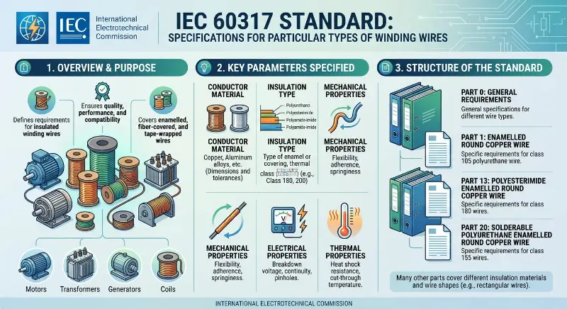
The technical parameters of standard aluminum enameled wire cover multiple dimensions, including conductor specifications, insulation class, enamel coating thickness, mechanical properties, and electrical properties. Regarding conductor specifications, the diameter of aluminum enameled round wire typically ranges from 0.16 to 9.2 mm. Fine wires with a diameter less than 0.5 mm are mainly used for high-frequency, low-power inductors; wires with a diameter of 1-3 mm are mainly used for medium-power magnetic components in inverters; and heavy-duty wires with a diameter greater than 5 mm are mainly used for power frequency transformers. Enamelled coating thickness is classified into three grades according to IEC standards: Grade 1 (G1, thin enamel coating), Grade 2 (G2, standard enamel coating), and Grade 3 (G3, thick enamel coating). Increasing the enamel coating thickness can improve voltage resistance but will reduce slot fill factor. Regarding insulation class, the IEC standard specifies the following relationship between insulation class and maximum operating temperature: Class E 120°C, Class B 130°C, Class F 155°C, Class H 180°C, Class C 200°C, and Class C+ 220°C. The hot spot temperature inside a photovoltaic inverter is typically between 100-150°C, and F-class (155°C) or H-class (180°C) enameled wire is a common choice. Centralized inverter reactors, due to their higher current and higher temperature, may require C-class (200°C) enameled wire. Regarding standards, the main international standards for enameled aluminum round wire include: IEC 60317-0-3, which specifies general requirements; IEC 60317-16, which specifies 130°C for polyester enameled aluminum round wire; IEC 60317-25, which specifies 200°C for polyester imide/polyamide-imide enameled aluminum round wire; IEC 60317-26, which specifies 200°C for polyamide-imide enameled aluminum round wire; IEC 60317-28, which specifies 180°C for polyester imide enameled aluminum round wire; and IEC 60317-29, which specifies 200°C for enameled aluminum rectangular wire. The North American standard NEMA MW 1000-2018 specifies 200°C for aluminum enameled round wire in MW 35-A/MW 35-C, 200°C for aluminum enameled rectangular wire in MW 36, and 130°C for polyurethane enameled round wire in MW 75-C. Commonly used enameled coating systems include: polyester (PE, 130°C), modified polyester (PE-mod, 155°C), polyurethane (PU, 130°C), polyester imide (PEI, 180°C), polyamide-imide (PAI, 200°C), and polyimide (PI, 220-240°C). Polyester imide (PEI) and polyamide imide (PAI) are the most commonly used enamel coating materials for enameled aluminum wires used in photovoltaic inverters, providing double-layer protection with primer and topcoat, respectively.
Performance Considerations for Aluminum Wires under High-Frequency Conditions
The impact of high-frequency conditions on the performance of aluminum enameled wires is a key consideration in design. The skin effect refers to the phenomenon that high-frequency alternating current tends to flow on the surface of a conductor, with the current density decreasing exponentially from the surface to the center. The formula for calculating the skin depth δ is δ = √(2ρ/ωμ), where ρ is resistivity, ω is angular frequency, and μ is permeability. For an aluminum conductor (resistivity 2.65 × 10⁻⁸ Ω·m), the skin depth at different frequencies is approximately 2.6 mm at 1 kHz, approximately 0.82 mm at 10 kHz, approximately 0.26 mm at 100 kHz, and approximately 0.082 mm at 1 MHz. When the conductor diameter is greater than twice the skin depth, the conductor center carries almost no current, effectively reducing the effective cross-sectional area. At 10 kHz, the conductor diameter should be less than 1.6 mm (within twice the 0.82 mm skin depth). At 100 kHz, the conductor diameter should be less than 0.5 mm. This means that for magnetic components with switching frequencies above 50 kHz, using fine enameled aluminum wire with a diameter of 0.5-1.0 mm is a suitable choice; for power frequency or low-frequency applications below 10 kHz, larger diameter aluminum wire can be used. The proximity effect refers to the phenomenon where high-frequency currents in adjacent conductors influence each other, causing current to concentrate on one side of the conductor. In transformers or coupled inductors, the proximity effect between multiple windings significantly increases AC resistance. At high frequencies, the AC resistance of a single heavy-duty wire can be much higher than the equivalent resistance of multiple thin wires connected in parallel. Litz wire (multi-strand insulated thin wire strands) is designed to address the proximity effect. Aluminum vs. Copper at high frequencies: Copper has a lower resistivity (1.68 × 10⁻⁸ Ω·m) than aluminum (2.65 × 10⁻⁸ Ω·m), but the skin depth is proportional to the square root of the resistivity; aluminum’s skin depth is approximately 1.26 times that of copper. This means that, for the same wire diameter, aluminum’s AC resistance is about 58% higher than copper’s. At power frequencies (50/60 Hz), the skin depth is much greater than the conductor diameter, and aluminum’s disadvantage is mainly reflected in its DC resistance. At high frequencies above 10 kHz, the disadvantage of aluminum’s AC resistance becomes more pronounced. At switching frequencies above 100 kHz, Litz wire designs or copper wire should be prioritized.

Typical Application Scenarios Analysis
The application of aluminum wire in photovoltaic inverters needs to be evaluated based on the specific operating characteristics of the magnetic components. Power frequency isolation transformers are the most suitable application for aluminum wire. These transformers operate at frequencies of 50/60 Hz, with large effective winding currents and high voltage ratings (400-800 V). Aluminum wire does not exhibit the skin effect problem under power frequency conditions, and power frequency transformers are typically large in size and weight, making the weight reduction effect of using aluminum wire significant. For rooftop string inverters, power frequency isolation transformers in the 5-30 kVA power range can simultaneously meet current density (2-3 A/mm²) and slot fill factor requirements using enameled aluminum rectangular wire (2-4 mm thick, 5-10 mm wide). Boost inductors are a potential application. Boost inductors operate at frequencies of 16-100 kHz, handling large DC bias and low ripple. The inductance value of a boost inductor is primarily determined by the permeability of the core, and it is relatively insensitive to high-frequency losses in the winding wire. However, the skin effect still exists at high frequencies, requiring selection of appropriate wire diameter based on the switching frequency. Below 30 kHz, 1-2 mm diameter enameled aluminum round wire can be used. At 50-100 kHz, Litz-structure enameled aluminum wire or copper wire should be considered. The application of filter inductors requires careful evaluation. LCL filter inductors operate at frequencies between 5-30 kHz, with ripple current frequencies matching the switching frequency. Filter inductors are sensitive to high-frequency losses; when using aluminum wire, the impact of increased AC resistance on filter efficiency needs to be calculated. Aluminum wire can be used in low switching frequency applications below 10 kHz; however, in applications above 20 kHz, the additional copper losses introduced by aluminum wire need to be evaluated. Common-mode chokes (CMCs) have a more specific application. CMCs are used to suppress common-mode EMI, operating in the conducted interference band from 150 kHz to 30 MHz. At such high frequencies, the skin effect of aluminum is extremely detrimental; CMCs almost exclusively use ferrite cores with copper enameled wire or copper Litz wire, making aluminum wire unsuitable.
Application Expansion of Copper-Clad Aluminum (CCA) Wire
Copper-clad aluminum (CCA) wire, as a bimetallic conductor, has unique application value in photovoltaics. The conductivity of CCA varies with the volume percentage of copper: Class 10A (10% copper by volume) is approximately 65% IACS, and Class 15A (15% copper by volume) is approximately 70% IACS. The main advantage of CCA in photovoltaic inverters lies in its end solderability. Compared to pure aluminum wire, the copper outer layer of CCA can be connected to copper terminals using conventional soldering processes. This characteristic gives CCA an engineering advantage in scenarios such as lead connections for power frequency isolation transformers and lead terminations for filter inductors. Pure aluminum wire requires copper-aluminum transition joints or specialized soldering processes in these scenarios, increasing manufacturing complexity and cost. CCA’s performance at high frequencies falls between that of pure aluminum and pure copper. At frequencies above 5 MHz, the current skin depth is less than the copper layer thickness, and current is primarily conducted within the copper layer, making the high-frequency performance of CCA close to that of pure copper. This characteristic means that CCA may outperform pure aluminum in mid-to-high frequency applications, but still falls short of pure copper. At switching frequencies of 10-100 kHz, CCA performs slightly better than pure aluminum but worse than pure copper. The electrical performance of the enameled aluminum wire and its end-connection process is crucial for the reliable operation of enameled aluminum wire in photovoltaic (PV) inverters. PV inverter bus voltages are typically between 600-1500 V, requiring the enameled aluminum wire to withstand sufficiently high breakdown voltages. IEC 60317-0-3 specifies the following breakdown voltage requirements: G1 minimum breakdown voltage 1.4 kV (peak), G2 2.8 kV, G3 4.2 kV. For applications with higher operating voltages, G2 or G3 enameled aluminum wire should be selected. The thermal shock resistance of the enameled aluminum wire is particularly important under the thermal cycling conditions of PV inverters. Photovoltaic inverters can reach temperatures of 60-70°C during the day under sunlight, dropping to ambient temperature at night, with a thermal cycling range of 40-50°C. The thermal shock resistance of the enamel coating should meet the relevant test requirements of IEC standards, including thermal shock testing (150-200°C/30 min) and softening breakdown testing. The chemical resistance of the enamel coating also needs attention. Encapsulating adhesives, thermal greases, and cleaning agents inside the photovoltaic inverter may chemically corrode the enamel coating. Polyester imides and polyamide imides exhibit good resistance to common chemicals.
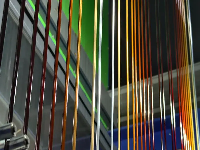
Enamel Coating and End Connection Process
Termination is a critical process in the application of aluminum wires in photovoltaic inverters. The main methods for termination of aluminum wires are as follows: Storage welding (CDW) is suitable for thin wire connections, achieving a joint strength of over 80% of the base material. Ultrasonic welding is suitable for connections between aluminum wires, requiring no flux. Cold pressing with copper-aluminum transition terminals is a common termination method; the copper terminal side can be connected to external circuits using conventional soldering. Copper-aluminum transition joints (flash welding, friction welding, composite strips) are key components connecting aluminum windings to external copper conductors.
Thermal Management and Reliability
The thermal environment of a photovoltaic inverter has a significant impact on the lifespan of aluminum wires. The operating temperature range for rooftop string inverters is typically -25°C to +70°C, while for centralized inverters it is -10°C to +45°C. Hot spot temperatures inside the inverter (including magnetic component areas) can be 30-50°C higher than ambient temperature. The lifespan of aluminum wires in relation to temperature follows the Arrhenius equation. For every 10°C increase in temperature, the rate of insulation aging approximately doubles. Class F (155°C) wires have an expected lifespan of approximately 20,000 hours at a continuous operating temperature of 130°C (IEC standard reference value); Class H (180°C) wires have an expected lifespan of approximately 20,000 hours at a continuous operating temperature of 155°C. In practical photovoltaic (PV) inverter applications, because the operating temperature is typically lower than the rated temperature, the actual lifespan is much longer than the reference value. Electrochemical corrosion is a potential failure mode at the connection points between aluminum windings and copper terminals or copper conductors. In humid environments, the aluminum-copper dissimilar metal contact can create a galvanic cell effect, with aluminum acting as the anode and preferentially corroding. PV inverters are usually installed indoors or within protective enclosures, where the risk of moisture is relatively low, but copper-aluminum transition joints or moisture-proof measures are still necessary at the connection points. Common failure modes of aluminum enameled wire include: enameled coating breakdown (voltage stress or thermal aging), enameled coating cracking (mechanical stress or thermal shock), increased end connection resistance (improper connection process or corrosion), winding short circuit (insulation failure), and winding open circuit (mechanical vibration or connection failure). In engineering applications, reliability verification should include: high-temperature storage testing (IEC 60068), thermal cycling testing (IEC 60068-2-14), damp heat cycling testing (IEC 60068-2-30), vibration testing (IEC 60068-2-6), and salt spray testing (IEC 60068-2-52).
Relevant Standards and Certifications
Aluminum enameled wire for photovoltaic inverters needs to meet multiple international and domestic standards. Regarding safety standards, IEC 62109-1 specifies the general safety requirements for photovoltaic inverters, while IEC 62109-2 specifies the specific safety requirements for inverters. UL 1741 is the North American safety standard for photovoltaic (PV) inverters. GB/T 37408 is the technical requirement for grid-connected PV power generation in China. These standards specify requirements for the thermal class, electrical strength, and flame retardant rating of insulation materials. Regarding winding wire standards, the IEC 60317 series of standards specifies the technical requirements for various types of enameled wire. ASTM B566 specifies the technical requirements for copper-clad aluminum wire (CCA). NEMA MW 1000-2018 specifies the technical requirements for enameled wire in the North American market. These standards have a high degree of correspondence in technical parameters, but their testing methods and certification systems differ. In terms of material standards, aluminum conductor material standards include EN 1715 (drawn aluminum and aluminum alloy wires), ASTM B230 (aluminum wire for electrical applications), and GB/T 3955 (round aluminum rods for electrical applications). These standards specify the chemical composition, conductivity, and mechanical properties of aluminum conductors. Regarding certifications, photovoltaic inverters require CE certification (Europe), UL certification (North America), and CQC certification (China). Winding wires, as key components, require corresponding material certifications and type test reports.
Selection Decision Points
The selection of aluminum wire for photovoltaic inverters should comprehensively consider factors such as operating frequency, current density, insulation class, environmental conditions, end connections, and cost budget. Operating frequency is the primary consideration. For power frequency (50/60 Hz) applications (power frequency isolation transformers), aluminum wire is most suitable, maximizing material cost and lightweight benefits. For mid-frequency (10-30 kHz) applications (boost inductors, low-frequency filter inductors), aluminum wire can be used, but high-frequency losses need to be calculated. For high-frequency (>50 kHz) applications (high-frequency isolation transformers, high-frequency filter inductors, common-mode chokes), copper wire or Litz wire should be prioritized. Insulation class selection should be based on thermal design results. Calculate the steady-state temperature rise of the winding under maximum load and select an enameled wire with an insulation class 10-20°C higher than that temperature rise. Common choices for photovoltaic inverters are Class F (155°C) or Class H (180°C). Wire diameter selection should consider skin depth and current density. Under power frequency conditions, select based on a current density of 2-3 A/mm²; under 10-30 kHz conditions, select based on a current density of 1.5-2 A/mm², and verify that the wire diameter is less than twice the skin depth. Conductor form selection should be based on the specific application. Enameled aluminum round wire is suitable for winding round coils and small inductors. Enameled aluminum rectangular wire (flat wire) is suitable for winding low-height transformers and high-slot full-rate inductors. Litz wire is suitable for high-frequency applications above 50 kHz. Enamel coating system selection should be based on insulation requirements. G1 enamel coating is suitable for low-voltage applications (<500 V), G2 enamel coating is suitable for medium-voltage applications (500-1500 V), and G3 enamel coating is suitable for high-voltage applications (>1500 V). In environments with a high risk of chemical corrosion, polyamide-imide (PAI) topcoat should be selected.
Conclusion
The application of aluminum in photovoltaic inverters is a process of weighing engineering trade-offs. In low-frequency, high-power scenarios such as power frequency isolation transformers, aluminum has significant economic and lightweight advantages; in medium-frequency scenarios such as boost inductors and filter inductors, the choice of aluminum needs to be comprehensively evaluated based on factors such as switching frequency, current density, and loss requirements; in high-frequency scenarios such as high-frequency isolation transformers and common-mode chokes, copper or Litz wire remains the mainstream choice. Understanding the performance boundaries of aluminum enameled wire in different application scenarios, mastering enameled coating and end connection processes, and complying with relevant standards and certification requirements are fundamental to the successful application of aluminum enameled wire in photovoltaic inverters.