


A photovoltaic (PV) inverter is the core power electronics device in a photovoltaic power generation system, responsible for converting direct current (DC) generated by PV modules into grid-compatible alternating current (AC). Aluminum foil serves as a critical material in PV inverters for magnetic component windings, power busbars, EMI shielding, heat-sink substrates, and grounding protection. It plays an essential role in key components such as boost inductors, transformers, filter inductors, common-mode inductors, DC busbars, and shielded enclosures. With the rapid advancement of the PV industry—including 1500 V high-voltage systems, string inverters, wide-bandgap semiconductors (SiC/GaN), and high-power-density designs—as well as the significant growth in demand for aluminum foil from new-energy vehicles and energy storage systems, application requirements and technical specifications for aluminum foil in PV inverters continue to rise. This document systematically outlines the fundamental architecture of PV inverters, the critical roles of aluminum foil therein, comparative analysis of aluminum foil versus copper foil, types and specifications of aluminum foil, manufacturing processes, typical applications, key performance requirements, selection criteria, and future development trends.
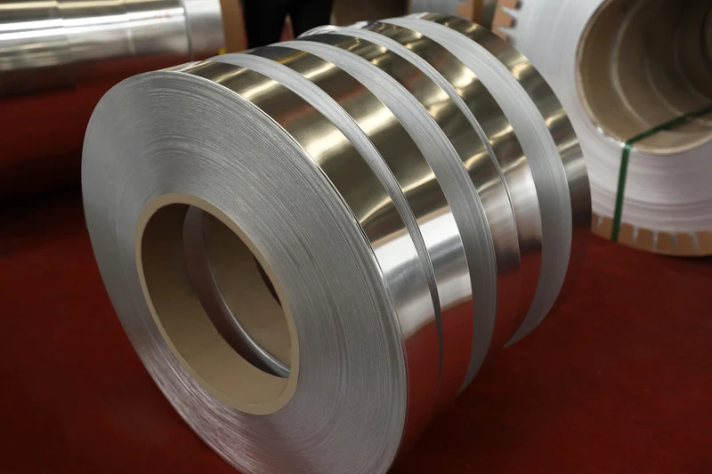
Basic Architecture and Working Principle of PV Inverters
A photovoltaic (PV) inverter is a critical power electronic device that interfaces photovoltaic (PV) modules with the utility grid. Its primary functions include: 1) converting DC power generated by PV modules (typically 30–1500 V) into grid-compatible AC power (single-phase 220 V / three-phase 380 V / medium-voltage 10–35 kV); 2) implementing maximum power point tracking (MPPT) to ensure PV modules consistently deliver maximum output power; 3) switching between grid-connected and off-grid operating modes; 4) grid fault protection—including anti-islanding, low-voltage ride-through (LVRT), and high-voltage ride-through (HVRT); 5) power quality control—such as harmonic suppression and power factor correction; and 6) data acquisition and remote monitoring.
Photovoltaic inverters are primarily categorized by power rating and application scenario as follows:
- Microinverter: Power rating 0.3–1 kW; one unit per photovoltaic (PV) module or per 2–4 PV modules; mounted on the rear side of PV modules; suitable for residential rooftop and small-scale distributed applications.
- Power Optimizer + String Inverter: Power optimizer rating 0.3–1 kW; string inverter rating 5–50 kW; suitable for residential and small commercial & industrial applications.
- Single-Phase String Inverter: Power rating 3–10 kW; single-phase AC 220 V output; suitable for residential rooftop applications.
- Three-Phase String Inverter: Power rating 5–350 kW; three-phase AC 380 V / 480 V / 800 V / 1000 V output; suitable for commercial & industrial applications and ground-mounted power plants.
- Central Inverter: Power rating 500 kW–2.5 MW; three-phase medium-voltage output; suitable for large-scale ground-mounted power plants.
- Distributed String Inverter: Power rating 1–3 MW; multiple string inverters paralleled and integrated; suitable for ground-mounted power plants with complex topography.
- Modular Inverter: Power rating 50 kW–1 MW; modular design facilitating scalability and maintenance.
Classified by electrical topology, photovoltaic inverters mainly include:
- Single-stage: Photovoltaic DC is directly inverted to AC; simple structure, but narrow MPPT range.
- Two-stage: Front-end Boost step-up stage + rear-end DC/AC inverter stage; wide MPPT range, most widely applied.
- Multi-stage: H-bridge cascaded, neutral-point-clamped (NPC), T-type, and modular multilevel converter (MMC).
Photovoltaic inverters are classified by output voltage levels into two-level (2L), three-level neutral-point-clamped (3L-NPC), five-level (5L), and multilevel (MMC) topologies. The 3L-NPC topology is most widely applied in 1000 V / 1500 V systems, significantly reducing switching losses and output harmonics.
Classified by switching frequency, the switching frequency of photovoltaic inverters depends on semiconductor technology:
- Conventional Si IGBT: switching frequency 3–20 kHz; mainstream for centralized inverters
- Si MOSFET: switching frequency 20–100 kHz
- SiC MOSFET: switching frequency 50–200 kHz; mainstream for string inverters
- GaN HEMT: switching frequency 100–500 kHz; used in next-generation high-frequency microinverters
Regarding inverter operating principles, photovoltaic inverters employ Pulse Width Modulation (PWM) technology based on power electronic switching devices—such as IGBTs, SiC MOSFETs, and GaN HEMTs—to convert DC input into Sinusoidal PWM (SPWM) or Space Vector PWM (SVPWM) waveforms via H-bridge, Neutral Point Clamped (NPC), or Modular Multilevel Converter (MMC) topologies; the resulting waveform is then filtered by an LCL filter to produce grid-synchronized AC output matching the utility grid in both frequency and phase. Core inverter control algorithms include Maximum Power Point Tracking (MPPT) algorithms (e.g., Perturb-and-Observe, Incremental Conductance, and intelligent MPPT algorithms), Phase-Locked Loop (PLL) synchronization, SPWM/SVPWM modulation, and grid-connection protection algorithms.
Regarding inverter efficiency, modern photovoltaic (PV) inverter efficiency metrics are as follows: European Efficiency (weighted average efficiency) 96–98.5%, China Efficiency 98–99.2%, maximum efficiency 98–99.5%, and MPPT efficiency 99.5–99.9%. SiC-based inverters achieve 0.5–1.5% higher efficiency than Si-based inverters. 1500 V systems deliver 0.3–0.5% higher efficiency than 1000 V systems.
Regarding inverter key components, photovoltaic inverters consist of the following key components:
- Magnetic components: Boost inductors, transformers, filter inductors (LCL), common-mode chokes, gate-drive transformers
- Power semiconductor devices: IGBTs, SiC MOSFETs, GaN HEMTs, freewheeling diodes
- DC bus capacitors: Electrolytic capacitors, film capacitors, ceramic capacitors
- Busbars: DC busbar, AC output busbar, grounding busbar
- Control board: MCU/DSP (TI C2000, Infineon Aurix), FPGA
- Gate-drive board: Gate drivers, isolated gate drivers
- Protection circuits: Overcurrent protection, overvoltage protection, undervoltage protection, overtemperature protection, surge protection (SPD)
- Thermal management system: Heat sink substrates (aluminum substrate, copper substrate), fans, liquid cooling
- EMC shielding: Core shielding, PCB shielding, enclosure shielding
- Structural components: Aluminum alloy enclosures, seals, connectors
Regarding inverter standards, photovoltaic inverter design must comply with multiple international standards:
- IEC 62109: Safety standard for photovoltaic inverters
- IEC 61727: Characteristics of grid-connected photovoltaic systems
- IEEE 1547: Standard for interconnecting distributed resources with electric power systems
- IEEE 929: Recommended practice for utility interface of photovoltaic (PV) systems
- UL 1741: Standard for inverters, converters, controllers and interconnection system equipment for use with distributed energy resources
- GB/T 19939: Technical requirements for grid connection of photovoltaic power generation systems
- NB/T 32004: Technical specification for grid-connected photovoltaic inverters
Key Functions of Aluminum Foil in PV Inverters
Aluminum foil serves multiple critical functions in photovoltaic inverters: winding of magnetic components, power busbars, EMI shielding, heat-dissipation substrates, and grounding protection.
In magnetic component winding, aluminum foil is a critical winding material for certain magnetic components in PV inverters—particularly low-power, low-current, and low-frequency components. Advantages of aluminum foil windings:
- Lightweight: Aluminum has a density of 2.70 g/cm³, only 30% that of copper; for the same current-carrying capacity, aluminum foil weighs approximately 30–40% that of copper foil.
- Low cost: Aluminum price is approximately one-third to one-quarter that of copper; for the same cross-sectional area, aluminum foil cost is significantly reduced.
- Excellent heat dissipation: Aluminum’s thermal conductivity is 237 W/m·K—lower than copper’s (400 W/m·K) but still superior to most non-metallic materials.
- High flexibility: Annealed (O-temper) pure aluminum exhibits elongation >30%, making it suitable for winding on complex-shaped magnetic cores.
- Easy formability: Aluminum possesses excellent plasticity and can be formed via rolling, stamping, drawing, and other processes.
Application limitations of aluminum foil windings in PV inverters:
- Higher electrical resistivity: Aluminum’s conductivity is 61% IACS; thus, its resistance is approximately 1.6 times that of copper at the same cross-sectional area.
- Skin effect: At high frequencies (>50 kHz), skin effect losses in aluminum foil remain significant.
- Joining process: Connection of aluminum foil to copper wire or copper busbars requires specialized processes (ultrasonic welding, crimping, or copper–aluminum transition connectors).
- Contact resistance: Aluminum surfaces readily form an Al₂O₃ oxide layer, resulting in relatively high contact resistance.
Regarding power busbars, aluminum foil or aluminum busbars can be used for the DC busbar (connecting the DC/DC boost converter output to the DC/AC inverter input), AC output busbar, and grounding busbar in PV inverters. Advantages of aluminum busbars:
– Lightweight: For the same current-carrying capacity, aluminum busbars weigh approximately 40% of copper busbars.
– Cost-effective: The cost of aluminum busbars is approximately 30–40% that of copper busbars.
– Excellent heat dissipation: Aluminum has a thermal conductivity of 237 W/m·K, making it suitable for high-current thermal management.
– Good workability: Easy to cut, punch, and bend.
Disadvantages of aluminum busbars:
- Higher electrical resistance: Approximately 1.6 times that of copper busbars at the same cross-sectional area
- Plating requirements: Aluminum busbars typically require tin or nickel plating to enhance solderability and oxidation resistance
- Long-term reliability: Oxidation and creep of aluminum busbars must be controlled during long-term operation
Regarding EMI shielding, high-frequency switching (3–500 kHz) in PV inverters—such as PFC, LLC, and DC/AC stages—generates substantial electromagnetic interference (EMI), including common-mode (CM) and differential-mode (DM) interference. Application of aluminum foil for EMI shielding in PV inverters:
- Core shielding: Aluminum foil wrapping of magnetic cores (boost inductors, transformers) to reduce magnetic field radiation from the core
- PCB shielding: Aluminum foil covering sensitive areas of the PCB to protect control signals from interference
- Enclosure shielding: Aluminum foil used as part of the overall equipment EMC shielding to suppress radiated emissions
- Shielded cables: Sensitive cables wrapped with aluminum foil + polyimide (PI)/polyethylene terephthalate (PET) composite tape
- Input/output filters: Aluminum foil used as shielding for common-mode (CM) and differential-mode (DM) filters
Advantages of aluminum foil EMC shielding: lightweight, low cost, and ease of forming into complex shapes. Disadvantages: aluminum’s electrical conductivity (61% IACS) is lower than copper’s (100% IACS), resulting in slightly reduced shielding effectiveness. However, within the primary interference frequency range of PV inverters—100 kHz to 30 MHz—the shielding effectiveness of aluminum foil meets the requirements of most applications.
Regarding heat-dissipating substrates, power devices such as IGBTs, SiC MOSFETs, and rectifier diodes in PV inverters require effective thermal management. Aluminum foil is applied as a heat-dissipating substrate—used in conjunction with aluminum-based and copper-based substrates.
- Chip-level thermal management: Aluminum foil is directly bonded to the bottom of the power chip as a thermal spreader.
- Module-level thermal management: Aluminum foil shims are placed between the power module and the cold plate to reduce interfacial thermal resistance.
- System-level thermal management: Aluminum foil heat sinks are welded onto the surface of heat-generating components to increase the heat dissipation area.
Advantages of aluminum foil heat dissipation: high thermal conductivity (237 W/m·K), lightweight, low cost, and ease of forming. Disadvantages: slightly lower heat dissipation capability compared to copper substrates (400 W/m·K), but sufficient for medium- and low-power PV inverters.
Regarding grounding protection, the PV inverter grounding system comprises protective earthing (PE), functional earthing (signal ground), and shield earthing. Application of aluminum foil as a grounding conductor:
- Ground busbar: Aluminum foil ground busbar connecting the grounding terminals of individual components
- PCB grounding: Aluminum foil serving as the PCB ground plane (inner layer of multilayer boards)
- Shield grounding: Aluminum foil shield grounded via a low-impedance path
- Chassis grounding: Aluminum enclosure connected to earth
Advantages of aluminum foil grounding: low resistance, lightweight, and low cost. Aluminum forms a dense Al₂O₃ oxide layer in atmospheric conditions, providing excellent weather resistance. Disadvantages: aluminum has lower electrical conductivity than copper; thus, for the same cross-sectional area, its grounding resistance is higher, necessitating either an increased cross-sectional area or the use of tin-plated aluminum foil.
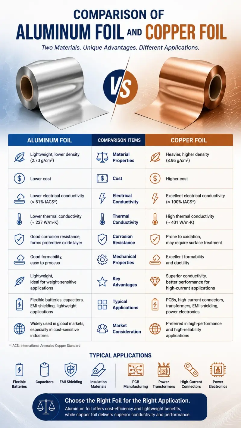
Comparison of Aluminum Foil and Copper Foil
Aluminum foil and copper foil are the two major categories of metallic foil materials used in PV inverters, exhibiting significant differences in weight, cost, electrical conductivity, thermal conductivity, mechanical properties, processability, and application scenarios.
Regarding weight, the density of aluminum is 2.70 g/cm³ and that of copper is 8.96 g/cm³; thus, aluminum weighs approximately 30% that of copper. In PV inverters, the total weight of aluminum foil (windings + busbars + shielding) is approximately 0.5–3 kg; substituting aluminum foil for copper foil reduces weight by 60–70%. In ground-mounted PV inverters (weighing 30–80 kg), the lightweighting benefit of aluminum foil is significant.
From a cost perspective, the market price of copper is approximately three to four times that of aluminum (based on 2024 data: copper at approximately CNY 60–80/kg, aluminum at approximately CNY 18–25/kg). Aluminum foil incurs significantly lower material costs compared to copper foil. In high-volume production of PV inverters, substituting aluminum foil for copper foil reduces material costs by 50–60%.
Regarding conductivity, copper has a conductivity of 100% IACS, while aluminum has a conductivity of approximately 61% IACS. For the same cross-sectional area, the resistance of aluminum foil is about 1.6 times that of copper foil. In high-efficiency (>98%) designs for PV inverters, the low resistance of copper foil remains critical. Aluminum foil is suitable for non-critical, low-current, and low-efficiency-sensitivity components.
Regarding thermal conductivity, copper has a thermal conductivity of 400 W/m·K, while aluminum has a thermal conductivity of 237 W/m·K. Copper exhibits superior thermal conductivity compared to aluminum. High-thermal-conductivity materials are required for heat dissipation of power devices in PV inverters; copper substrates remain the preferred choice for high-end applications, whereas aluminum substrates are widely used in medium- and low-power PV inverters.
Regarding mechanical properties, copper has a tensile strength of 220–400 MPa and elongation of 15–30%. Aluminum has a tensile strength of 80–150 MPa (O-temper) and elongation of 20–35%. Aluminum exhibits superior flexibility and ductility compared to copper, facilitating bending and forming; however, its strength is lower than that of copper. Busbars for PV inverters require sufficient mechanical strength to withstand vibration and thermal stress; copper busbars remain predominant in critical applications.
Regarding processability, copper foil exhibits a higher degree of manufacturing maturity and can be produced via multiple processes including rolling, electrolytic deposition, and electroplating, with thickness ranging from 0.01 mm to 0.50 mm. Aluminum foil manufacturing is also mature, with thickness ranging from 0.005 mm to 0.50 mm. Copper foil joining processes (e.g., welding, crimping, winding) are well established, whereas aluminum foil joining requires specialized techniques.
In terms of application scenarios, aluminum foil and copper foil in PV inverters are complementary.
– Aluminum foil: non-critical low-current components (auxiliary inductors, auxiliary transformers), large-size busbars, shielding, heat-dissipation substrates, grounding
– Copper foil: critical high-current components (main transformers, LCL filter inductors, power busbars), high-efficiency components, high-frequency components
Relationship between aluminum foil and copper foil applications:
- Low-power microinverters (<1 kW): Aluminum foil can largely replace copper foil (cost-driven).
- Residential string inverters (3–10 kW): Aluminum foil partially replaces copper foil (shielding, auxiliary components).
- Commercial & industrial string inverters (10–100 kW): Aluminum foil is used for shielding, heat dissipation, and auxiliary functions; copper foil is used for main magnetic components.
- Centralized inverters (>500 kW): Copper foil remains dominant; aluminum foil is used only in non-critical paths.
Regarding connection methods, special processes are required for connecting aluminum foil to copper foil:
- Ultrasonic welding: Aluminum–copper ultrasonic welding is a mature joining process offering high joint strength and low electrical resistance.
- Crimping: Aluminum–copper crimping employs dedicated copper–aluminum transition connectors.
- Copper–aluminum transition connectors: Use copper-clad aluminum (CCA) or aluminum-clad copper (CA) transition connectors.
- Soldering/brazing: Aluminum–copper brazing uses specialized filler metals (e.g., zinc-based brazing alloys).
Types and Specifications of Aluminum Foil
Aluminum foil for PV inverters is classified by manufacturing process, alloy composition, temper, thickness, and surface treatment.
Regarding manufacturing processes, aluminum foil is categorized into two major types.
- Rolled Aluminum Foil: Manufactured via rolling process, wherein aluminum ingots undergo multiple hot rolling, cold rolling, and annealing steps to produce foil. Characteristics of rolled aluminum foil include double-sided smoothness, excellent flexibility, and high elongation. Typical thickness: 0.05–0.50 mm. Rolled aluminum foil is the mainstream choice for PV inverter aluminum foil.
- Cast-Rolled Aluminum Foil: Manufactured via cast-rolling process, wherein molten aluminum is directly cast-rolled into thin strip, followed by cold rolling to produce foil. Characteristics of cast-rolled aluminum foil include lower cost and slightly inferior thickness uniformity. Typical thickness: 0.10–0.50 mm. Cast-rolled aluminum foil is also applied in PV inverters.
Regarding alloy composition, aluminum foil for PV inverters is primarily pure aluminum (1xxx series), with commonly used grades including:
- 1050 aluminum foil: Al ≥99.50%, Si+Fe ≤0.45%, low impurity content, electrical conductivity 61% IACS, thermal conductivity 230 W/m·K
- 1060 aluminum foil: Al ≥99.60%, Si+Fe ≤0.35%, lower impurity content, electrical conductivity 62% IACS
- 1070 aluminum foil: Al ≥99.70%, Si+Fe ≤0.25%, lowest impurity content, electrical conductivity 62.5% IACS
- 1350 aluminum foil: Al ≥99.50%, Si+Fe ≤0.50%, electrical conductivity 61% IACS, specifically designed for electrical conduction applications
Aluminum alloy foil is used in certain specialized applications:
- 3003 aluminum foil (Al–Mn alloy, Mn 1.0–1.5%): higher strength than pure aluminum (tensile strength 140–180 MPa); used for components requiring mechanical strength
- 5052 aluminum foil (Al–Mg alloy, Mg 2.2–2.8%): tensile strength 170–305 MPa; used for structural parts and busbars
- 6061 aluminum foil (Al–Mg–Si alloy): high strength, heat-treatable; used for structural parts
In terms of temper, aluminum foil is classified as hard (H), half-hard (1/2H), or annealed (O) based on the degree of annealing. PV inverter aluminum foil primarily employs annealed (O) or half-hard (1/2H) rolled aluminum foil to ensure bendability and electrical conductivity. Hard-temper aluminum foil exhibits low elongation (<10%) and is prone to cracking during bending.
Regarding thickness, common thickness specifications for aluminum foil used in PV inverters:
- 0.05–0.10 mm: Thin-gauge high-frequency applications, shielding
- 0.10–0.20 mm: Standard magnetic component winding, shielding
- 0.20–0.30 mm: Standard busbar, winding
- 0.30–0.50 mm: Thick-gauge high-current busbar, interconnection
- 0.5–1.0 mm: Ultra-thick-gauge main busbar, heat-dissipation substrate
In terms of width, common width specifications for aluminum foil used in PV inverters:
- 10–30 mm: Magnetic component windings
- 30–80 mm: Large-size windings, shielding
- 80–200 mm: Busbars, shielding
- 200–500 mm: Ultra-wide shielding, heat dissipation
Regarding surface treatment, aluminum foil surface treatment is a critical process for PV inverters, directly affecting conductivity, solderability, corrosion resistance, and contact resistance.
- Untreated aluminum surface: Naturally formed Al₂O₃ oxide film; slightly reduced conductivity
- Copper plating: Copper layer (Cu, 5–20 μm) applied to surface for improved solderability with copper components and enhanced conductivity
- Nickel plating: Nickel layer (Ni, 1–5 μm) applied to surface for corrosion resistance and improved solderability
- Tin plating: Tin layer (Sn, 5–25 μm) applied to surface for improved solderability
- Silver plating: Silver layer (Ag, 1–3 μm) applied to surface for maximum conductivity
- Chemical treatment: Chromate or phosphate conversion coating to enhance corrosion resistance
- Anodizing: Formation of porous Al₂O₃ insulating layer
Regarding composite configurations, aluminum foil for PV inverters is available in the following composite forms:
- Plain aluminum foil: Bare aluminum strip requiring surface treatment
- Copper-clad aluminum (CCA) foil: Aluminum core with copper cladding; optimal cost-performance ratio
- Nickel-coated aluminum (Ni-coated Al) foil: Corrosion-resistant and solderable
- Aluminum + polyimide (Al+PI) composite tape: Aluminum foil laminated with polyimide film; temperature resistance from –200 °C to +260 °C
- Aluminum + polyethylene terephthalate (Al+PET) composite tape: Aluminum foil laminated with polyester film; temperature resistance from –40 °C to +150 °C
- Aluminum-plastic composite tape (Al+Mylar): Aluminum foil with Mylar insulation layer
- Aluminum foil + ceramic-filled insulation layer: High dielectric strength and high thermal conductivity
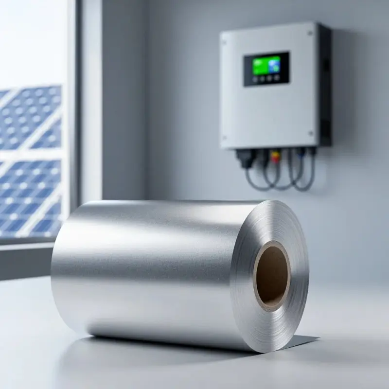
Manufacturing Process of Aluminum Foil
The manufacturing process of aluminum foil for PV inverters varies depending on the type. Rolled aluminum foil is the predominant substrate for PV inverters, and its manufacturing process is as follows:
Manufacturing process of rolled aluminum foil:
- Melting: Pure aluminum ingots (Al ≥99.5%) are heated to 660–750°C in a melting furnace to melt, followed by addition of alloying elements (e.g., Mg, Mn) to adjust composition.
- Refining: Inert gases (argon or nitrogen) are purged or fluxes are applied to remove hydrogen and non-metallic inclusions.
- Casting: Semi-continuous casting (Vertical Direct Chill Casting) or continuous casting is employed to produce aluminum slabs or ingots with thicknesses of 100–500 mm.
- Homogenization annealing: Holding at 500–600°C for 4–24 hours to eliminate as-cast segregation.
- Hot rolling: Aluminum ingots undergo multi-pass hot rolling on a hot rolling mill to reduce thickness from 100–500 mm to 4–8 mm; hot rolling temperature: 400–500°C.
- Intermediate annealing: Hot-rolled aluminum strip is subjected to intermediate annealing at 300–400°C for 2–8 hours to relieve work hardening.
- Cold rolling: Aluminum strip is cold rolled at room temperature through multiple passes to reduce thickness from 4–8 mm to 0.1–0.5 mm; cold rolling induces work hardening.
- Intermediate annealing: Intermediate annealing is performed during cold rolling at 250–350°C for 1–4 hours to relieve work hardening.
- Final cold rolling: Further cold rolling to target thickness of 0.05–0.50 mm.
- Final annealing: Final annealing at 200–350°C renders the aluminum foil in soft temper (O) or half-hard temper (1/2H), with elongation >20–30%.
- Surface cleaning: Acid/alkali pickling and polishing to remove oxide layers.
- Surface treatment (optional): Electroplating, chemical conversion coating, or anodizing.
- Coiling and packaging.
Aluminum foil surface treatment (electroplating) process:
- Pretreatment: Alkaline cleaning for oil removal, acid pickling for oxide layer removal, water rinsing, and activation (brightening).
- Electroplating: Electroplating is performed in plating tanks according to coating type:
– Copper plating: Copper sulfate + sulfuric acid electrolyte, current density 1–5 A/dm², bath temperature 20–40 °C
– Nickel plating: Nickel sulfate + nickel chloride electrolyte, pH 3.5–4.5, current density 2–10 A/dm²
– Tin plating: Stannous sulfate electrolyte, current density 1–5 A/dm²
– Silver plating: Cyanide-based or cyanide-free electrolyte, current density 0.5–2 A/dm² - Post-treatment: Water rinsing, passivation (tarnish prevention), and drying.
- Reeling and slitting.
Key quality indicators of aluminum foil:
- Purity: Al ≥99.5% (1050/1350), ≥99.6% (1060), ≥99.7% (1070)
- Electrical conductivity: ≥61% IACS (pure aluminum)
- Thermal conductivity: ≥200 W/m·K
- Thickness tolerance: ±5% to ±10%
- Width tolerance: ±0.5 mm
- Surface roughness: Ra <0.5 μm
- Tensile strength: O temper 80–150 MPa
- Elongation: O temper >20–35%
- Hardness: HV 25–45
- Coating thickness: Cu 5–20 μm, Ni 1–5 μm, Sn 5–25 μm, Ag 1–3 μm
Applications in Boost Inductor and DC-DC Conversion
The boost inductor is the core magnetic component of the DC–DC boost converter in photovoltaic inverters, operating at a frequency range of 3–200 kHz (3–50 kHz for Si-based and 50–200 kHz for SiC-based systems), with inductance values ranging from 100–2000 μH and peak currents of 5–50 A. Aluminum foil may be used as the winding material for boost inductors—particularly in low- and medium-power inverters.
Recommended aluminum foil for boost inductors:
- Microinverters (0.3–1 kW): aluminum foil, 0.10–0.20 mm thick × 10–25 mm wide
- Residential string inverters (3–10 kW): aluminum foil, 0.15–0.25 mm thick × 15–30 mm wide
- Commercial & industrial string inverters (10–100 kW): aluminum foil, 0.20–0.30 mm thick × 20–40 mm wide (cost-driven), or copper foil (efficiency-driven)
Key considerations for boost inductor aluminum foil: The skin effect of aluminum foil becomes significant above 50 kHz, requiring optimization of the thickness-to-width ratio of the aluminum foil. At a frequency of 100 kHz, the skin depth of aluminum is approximately 0.26 mm; therefore, the aluminum foil thickness should be less than 0.20 mm to minimize skin effect losses.
Regarding DC busbars, the DC bus (connecting the DC/DC output to the DC/AC input) of PV inverters must carry high current (10–100 A), typically implemented using laminated aluminum busbars or multi-layer aluminum foil stack structures. A typical laminated aluminum busbar structure comprises multiple layers of aluminum foil (each 0.10–0.30 mm thick) plus insulating layers (polyimide/polyester film). The low parasitic inductance (<10 nH) of laminated aluminum busbars significantly reduces switching overshoot, thereby protecting SiC/GaN devices.
Advantages of Aluminum DC Busbars:
- Lightweight: 60% weight reduction compared to copper busbars
- Cost-effective: 50% lower cost compared to copper busbars
- Excellent heat dissipation: Aluminum’s thermal conductivity is 237 W/m·K, suitable for high-current thermal management
Limitations of Aluminum DC Busbars:
- Higher electrical resistance: Resistance increases by 60% at the same cross-sectional area compared to copper busbars.
- Plating requirements: Tin plating or nickel plating is required to enhance solderability and oxidation resistance.
- High-current application limitations: Copper busbars remain the mainstream solution for high-current applications exceeding 100 A.
Applications in Transformer and Filter Inductor
The isolation transformer is a core magnetic component in PV inverters’ DC–AC inverters or DC–DC converters, operating at frequencies of 3–500 kHz. The winding material—copper foil or aluminum foil—is selected based on power rating and cost considerations.
Transformer aluminum foil applications:
- Microinverters (0.3–1 kW): aluminum foil, 0.10–0.20 mm thick × 15–30 mm wide
- Residential string inverters (3–10 kW): aluminum foil, 0.20–0.30 mm thick × 20–40 mm wide (secondary winding)
- Commercial & industrial string inverters (10–50 kW): aluminum foil, 0.30–0.50 mm thick × 30–60 mm wide (in selected applications)
- Central inverters (>500 kW): copper foil is predominant; aluminum foil is used only for auxiliary windings
Key Technologies for Transformer Aluminum Foil:
- Winding structure: Primary high-voltage side uses aluminum foil or enameled round wire; secondary low-voltage side uses thick-gauge aluminum foil.
- Insulation layer: Aluminum foil laminated with polyimide (PI) film; dielectric strength ≥5 kV.
- Leakage inductance control: The flat profile of aluminum foil helps reduce leakage inductance (<1 μH).
- Heat dissipation: High surface area of aluminum foil facilitates heat dissipation.
Regarding LCL filter inductors, the output LCL filter of PV inverters—comprising the inverter-side inductor L1, grid-side inductor L2, and filter capacitor C—must carry high currents at power frequency or low frequencies (peak current 10–100 A); using aluminum foil windings significantly reduces cost and weight. Recommended aluminum foil solution for LCL filter inductors:
- Single-phase string (3–10 kW): aluminum foil, 0.20–0.30 mm thick × 20–40 mm wide
- Three-phase string (10–100 kW): aluminum foil, 0.30–0.50 mm thick × 30–60 mm wide
- Centralized inverters (>500 kW): copper foil is predominant
For common-mode chokes (CM Chokes), toroidal cores (ferrite or nanocrystalline) are used in EMI filters of PV inverters; windings may be aluminum foil or enameled wire. Aluminum foil windings for common-mode chokes: foil thickness 0.05–0.15 mm × width 10–30 mm, number of turns 5–30.
Regarding auxiliary power transformers, the auxiliary power supply (flyback converter) of PV inverters delivers 12 V / 15 V / 24 V outputs with a power rating of 10–100 W. Aluminum foil windings may be employed for auxiliary power transformers—particularly in medium- and low-power applications—with aluminum foil dimensions of 0.10–0.20 mm thickness × 10–25 mm width.
For gate drive transformers, PV inverters employ IGBT/SiC MOSFET gate drive transformers (isolated drive) with aluminum foil windings (ultra-thin specifications), where the aluminum foil dimensions are 0.05–0.10 mm in thickness × 5–15 mm in width, operating at a frequency range of 50–200 kHz.
Applications in EMC Shielding and Heat Dissipation
EMC shielding and thermal management systems for PV inverters represent a key application area for aluminum foil.
Regarding EMC shielding, high-frequency switching (3–500 kHz) in PV inverters—such as PFC, LLC, and DC/AC stages—generates substantial electromagnetic interference (EMI), which must comply with standards including CISPR 11, CISPR 22, EN 55011, EN 55022, and GB/T 17626. Applications of aluminum foil for EMC shielding in PV inverters include:
- Core shielding: Aluminum foil wrapping the cores of boost inductors, transformers, and filter inductors to suppress magnetic field radiation. Aluminum foil thickness: 0.05–0.10 mm; width: 20–50 mm; applied with overlapping winding.
- PCB shielding: Aluminum foil covering sensitive PCB areas (control signals, analog signals) to protect against high-frequency interference. Aluminum foil + polyimide (PI)/polyethylene terephthalate (PET) composite tape thickness: 0.05–0.20 mm.
- Enclosure shielding: Aluminum foil used as part of the system-level EMC shielding (in conjunction with aluminum enclosures) to suppress radiated emissions. Aluminum foil thickness: 0.10–0.30 mm, applied to the inner surface of the enclosure.
- Cable shielding: Aluminum foil + PI/PET composite tape wrapping sensitive cables (signal lines, drive lines) to suppress conducted interference.
- Filter shielding: Aluminum foil employed as the shielding layer of EMI filters to suppress self-radiation from the filters.
Effectiveness of aluminum foil EMC shielding:
- 30–100 MHz: aluminum foil shielding effectiveness: 60–80 dB (thickness: 0.10 mm)
- 100–1000 MHz: aluminum foil shielding effectiveness: 50–70 dB
- 1–30 MHz: aluminum foil shielding effectiveness: 70–90 dB
- 100 kHz–30 MHz (main interference frequency band of PV inverters): aluminum foil shielding effectiveness meets requirements
Regarding thermal management systems, power devices such as IGBTs, SiC MOSFETs, and rectifier diodes in PV inverters require effective heat dissipation. Application of aluminum foil in PV inverter thermal management systems:
- Chip-level thermal management: Aluminum foil is directly bonded to the bottom of power chips as a thermal spreader layer (thickness: 0.05–0.20 mm).
- Module-level thermal management: Aluminum foil shims are placed between power modules and cold plates (thickness: 0.10–0.50 mm) to reduce interfacial thermal resistance.
- Heat sink substrate: Aluminum-based substrates (Al substrates, thickness: 1–3 mm) represent the mainstream thermal management solution for medium- and low-power inverters.
- System-level thermal management: Aluminum foil heat sinks are welded onto the surfaces of heat-generating components (thickness: 0.10–0.30 mm).
Key parameters for aluminum foil heat dissipation:
- Thermal conductivity: 237 W/m·K (pure aluminum)
- Specific heat capacity: 900 J/(kg·K)
- Coefficient of thermal expansion: 23.1×10⁻⁶/°C
- Density: 2.70 g/cm³
Key Performance Requirements and Testing Methods
Key performance requirements for aluminum foil used in PV inverters include: electrical conductivity, thermal conductivity, purity, thickness tolerance, surface quality, mechanical properties, temperature resistance, chemical resistance, and electrical insulation properties.
Regarding conductivity, the conductivity of aluminum foil is tested in accordance with IEC 60093 or ASTM B193. The conductivity of aluminum foil for PV inverters shall be ≥61% IACS (pure aluminum 1050/1350); high-purity aluminum (1060/1070) achieves 62–62.5% IACS. Conductivity directly affects copper losses in aluminum foil windings and voltage drop across power busbars.
Regarding thermal conductivity, the thermal conductivity of aluminum foil is approximately 237 W/m·K. Thermal conductivity testing is performed per ASTM D5470 or the laser flash method. Thermal conductivity affects the heat dissipation performance of aluminum foil heat-sink substrates and windings.
Regarding purity, aluminum foil purity is tested per ASTM E478 or ICP-OES. For PV inverters, aluminum foil purity shall be ≥99.5% (1050/1350), ≥99.6% (1060), and ≥99.7% (1070). Impurity content—particularly Si, Fe, Cu, and Mn—affects electrical conductivity, thermal conductivity, and mechanical properties.
Regarding thickness tolerance, aluminum foil thickness is tested per ASTM E252. The thickness tolerance for aluminum foil used in PV inverters is typically ±5% to ±10%. Thickness tolerance directly affects the cross-sectional area, resistance calculation, and current-carrying capacity of the aluminum foil.
Regarding surface quality, the surface roughness of aluminum foil is tested in accordance with ISO 4287 or ASTM D7127. The surface roughness Ra of aluminum foil is <0.5 μm (bright finish). Surface quality affects coating adhesion and contact resistance of the aluminum foil.
Regarding mechanical properties, the tensile strength and elongation of aluminum foil are tested in accordance with ASTM E8. Typical mechanical property requirements for aluminum foil used in PV inverters: tensile strength 80–150 MPa (O temper), elongation >20–35%, hardness HV 25–45.
Regarding thermal endurance, aluminum foil itself exhibits excellent thermal resistance (aluminum melting point: 660 °C); however, the thermal endurance of aluminum foil composite tapes is limited by the insulating material: aluminum foil + polyimide (PI) composite tape has an operating temperature range of –200 °C to +260 °C, while aluminum foil + polyethylene terephthalate (PET) composite tape has an operating temperature range of –40 °C to +150 °C. The typical operating temperature range for PV inverters is –40 °C to +85 °C (outdoor applications).
Regarding chemical resistance, the aluminum foil’s chemical resistance is evaluated according to IEC 60068-2-52 (salt mist test):
- Neutral Salt Spray (NSS): 5% NaCl solution, 35°C, 96–1000 hours
- Acetic Acid Salt Spray (ASS): pH 3.1–3.3, 96 hours
- Copper-Accelerated Acetic Acid Salt Spray (CASS): pH 3.1–3.3, containing CuCl₂, 48 hours
Acceptance criteria: No visible corrosion on the aluminum foil surface; no peeling of the coating. Aluminum forms a dense Al₂O₃ oxide layer in atmospheric conditions, providing excellent weather resistance.
Regarding electrical performance, the dielectric breakdown voltage of aluminum foil windings is a critical safety parameter for PV inverters. The dielectric breakdown voltage of the aluminum foil + polyimide (PI) composite tape correlates with the PI film thickness: ≥5000 V for 0.025 mm PI and ≥10000 V for 0.050 mm PI. The isolation withstand voltage between the input side (PV DC) and output side (grid AC) of PV inverters is typically required to be ≥4 kVAC for 1 minute.
Regarding reliability testing, aluminum foil for PV inverters must pass a series of reliability tests: thermal cycling (–40 °C to +125 °C, 1,000 cycles), damp heat cycling (85 °C/85 % RH, 1,000 h), vibration (5–2,000 Hz, 10–30 g), mechanical shock (50 g, 11 ms), drop testing, and long-term aging testing. After reliability testing, aluminum foil windings, busbars, shielding, and heat-dissipating substrates shall exhibit no cracking, delamination, blistering, or performance degradation.
Selection Decision Recommendations
Selection of aluminum foil for PV inverters shall be based on a comprehensive assessment of power rating, switching frequency, efficiency requirements, cost, mechanical environment, and thermal environment.
Recommended by inverter power rating:
- Microinverters (0.3–1 kW): Aluminum foil, 0.10–0.20 mm thick × 10–30 mm wide; largely replaces copper foil (cost-driven).
- Residential single-phase string inverters (3–10 kW): Aluminum foil, 0.15–0.25 mm thick × 15–30 mm wide; partially replaces copper foil.
- Residential three-phase string inverters (10–25 kW): Aluminum foil, 0.20–0.30 mm thick × 20–40 mm wide (for auxiliary inductors and shielding); copper foil used for main inductors.
- Commercial & industrial three-phase string inverters (25–100 kW): Aluminum foil, 0.20–0.30 mm thick × 20–50 mm wide (for shielding and auxiliary functions); copper foil used for main transformers and main inductors.
- Large-scale three-phase string inverters (100–350 kW): Aluminum foil, 0.30–0.50 mm thick × 30–60 mm wide (for shielding and heat dissipation); copper foil used for main transformers and main busbars.
- Central inverters (500 kW–2.5 MW): Copper foil is predominant; aluminum foil used only in non-critical paths.
Recommended by application component:
- Boost inductor winding: aluminum foil, 0.10–0.30 mm thick × 10–40 mm wide
- LCL filter inductor: aluminum foil, 0.20–0.50 mm thick × 20–60 mm wide
- Common-mode inductor: aluminum foil, 0.05–0.15 mm thick × 10–30 mm wide
- Auxiliary power transformer: aluminum foil, 0.10–0.20 mm thick × 10–25 mm wide
- Gate drive transformer: aluminum foil, 0.05–0.10 mm thick × 5–15 mm wide
- DC busbar: multi-layer aluminum foil stack (each layer 0.10–0.30 mm), total thickness 0.3–1.0 mm
- AC output busbar: aluminum foil, 0.30–0.50 mm thick × 50–200 mm wide
- EMC shielding: aluminum foil, 0.05–0.20 mm thick × 20–200 mm wide
- Heat dissipation baseplate: aluminum foil, 0.10–0.50 mm thick × 30–100 mm wide
Recommended according to reliability requirements:
- Residential inverters: Standard aluminum foil, grades 1050/1060, surface cleaned
- Commercial & industrial inverters: Pure aluminum, grade 1070, corrosion-resistant chemical treatment (chromate)
- Centralized inverters: Pure aluminum, grade 1070, chemical treatment + nickel plating
- Coastal/high-humidity environments: Pure aluminum, grade 1070, chemical treatment + tin plating or nickel plating
- Desert/high-temperature environments: High-temperature-resistant aluminum foil, grades 3003/5052, high-temperature insulation layer (polyimide, PI)
Not recommended options:
- Aluminum foil as a substitute for critical high-current components: Significant resistive losses in aluminum foil make it unsuitable for high-current applications (>50 A) and high-efficiency applications (>98%).
- Pure aluminum foil (without surface treatment): Al₂O₃ oxide layer results in high contact resistance and susceptibility to corrosion.
- Hard-temper aluminum foil (H temper): Low elongation (<10%), prone to cracking during bending.
- Aluminum foil that is too thin (<0.05 mm): Low mechanical strength, easily damaged.
- Aluminum foil that is too thick (>0.5 mm): Large bending radius, difficult to wind, low space utilization.
- Low-quality aluminum alloy foil (high impurity content): Low electrical conductivity and poor mechanical properties.
- Direct aluminum–copper welding: Al₂O₃ oxide layer causes welding failure; copper–aluminum transition connectors are required.
Future Development Trends
Continuous innovation and upgrading of PV inverter technology will drive ongoing evolution of aluminum foil application technology, with key trends including:
Regarding 1500 V systems, 1500 V photovoltaic systems have become the mainstream design for large-scale ground-mounted power plants. Compared with 1000 V systems, 1500 V systems can reduce cable losses by 30–50% and balance-of-system (BOS) costs by 5–10%. Leading manufacturers—including Sungrow, TBEA, East Group, and Ginlong—have launched 1500 V string inverters (80–352 kW). 1500 V systems require the insulation dielectric strength of aluminum foil to be increased from 1000 V to ≥1500 V.
Regarding string inverters, string inverters have gradually replaced central inverters as the mainstream solution for large-scale ground-mounted power plants, capturing a market share exceeding 70% in 2024. The high power density (>3 kW/L) of string inverters demands smaller and more efficient aluminum foil windings, busbars, shielding, and thermal management systems. The application share of aluminum foil in string inverters will continue to increase.
Regarding SiC/GaN wide-bandgap semiconductors, SiC/GaN devices increase the switching frequency of PV inverters from 3–50 kHz (Si-based) to 50–500 kHz. This high-frequency operation significantly reduces skin-effect losses in aluminum foil windings, driving the reduction of aluminum foil thickness from 0.20–0.30 mm to 0.10–0.20 mm, while also requiring thinner insulation layers (polyimide [PI] reduced from 0.050 mm to 0.025 mm).
Regarding energy storage integration (PCS), hybrid inverters—integrating PV inverter and energy storage PCS—have become mainstream in both residential and commercial & industrial markets. Magnetic components and DC/DC converters in energy storage PCS have aluminum foil requirements similar to those of PV inverters; thus, aluminum foil application in hybrid inverters for energy storage integration will further expand.
Regarding modular design, PV inverters are transitioning from monolithic to modular architectures, with each power module independently designed and plug-in capable. Modular design necessitates standardization and compactness of aluminum foil assemblies. Demand for modular aluminum foil assemblies—including aluminum foil inductor modules, aluminum foil busbar modules, and aluminum foil heat dissipation modules—will continue to grow.
Regarding intelligent manufacturing, the intelligent manufacturing direction for PV inverters includes: online thickness measurement (X-ray thickness gauge), online defect detection (CCD vision system), automated winding (CNC winding machine), automated assembly (robot), and automated testing. Intelligent manufacturing enhances consistency, reliability, and production efficiency of aluminum foil components.
Regarding lightweighting (aluminum substitution for copper), the demand for lightweight PV inverters is driving the trend of aluminum substitution for copper. In low-power microinverters and residential string inverters, aluminum foil can largely replace copper foil (windings, busbars, shielding). In medium-power string inverters, aluminum foil partially replaces copper foil (shielding, auxiliary windings, heat dissipation). Aluminum substitution for copper technology will further reduce the cost and weight of PV inverters, enhancing market competitiveness.
Regarding environmental upgrades, environmental requirements for PV inverters are becoming increasingly stringent, with lead-free, halogen-free, and recyclable materials becoming mainstream. Aluminum foil’s recyclability (aluminum recycling rate >95%) makes it an environmentally friendly choice. Additionally, aluminum foil’s lightweighting benefits reduce transportation-related carbon emissions.
Regarding AI intelligent monitoring, AI technology is applied in PV inverters as follows: AI-based fault diagnosis (IGBT/SiC fault prediction), AI-based efficiency optimization (intelligent MPPT algorithms), AI-based remote monitoring (cloud-based data analytics), and AI-based visual inspection (welding defects, assembly defects). AI technology enhances the reliability and efficiency of PV inverters.
Conclusion
Aluminum foil is a critical conductive and structural material in photovoltaic (PV) inverters, playing a key role in magnetic component windings (secondary inductors, auxiliary transformers), power busbars (DC/AC busbars), EMI shielding, heat-dissipation substrates, and grounding protection. Compared with copper foil, aluminum foil offers significant advantages including 30% lower weight, 30% lower cost, superior flexibility, and excellent formability, making it a key material for lightweighting and cost optimization of PV inverters.
Aluminum foil for PV inverters is categorized by manufacturing process into two main types: rolled aluminum foil (dominant) and cast-rolled aluminum foil (minority); by alloy composition into two main types: pure aluminum (1050/1060/1070/1350, Al ≥99.5–99.7%) and aluminum alloys (3003/5052/6061); by thickness into multiple grades ranging from 0.05 mm to 0.50 mm; and by surface treatment into bare aluminum surface, copper-plated, nickel-plated, tin-plated, silver-plated, chemically treated, and anodized.
Aluminum foil selection shall be determined comprehensively based on inverter power rating, application component, and reliability requirements. Aluminum foil may be used predominantly in low-power micro-inverters (<1 kW), partially in residential string inverters (3–10 kW), and only in non-critical paths in commercial & industrial string inverters (10–100 kW); for central inverters (>500 kW), copper foil is primary, with aluminum foil restricted to non-critical paths.
With the rapid development of the photovoltaic industry—including 1500 V systems, string inverters, SiC/GaN wide-bandgap semiconductors, energy storage integration, modular design, intelligent manufacturing, lightweighting (aluminum replacing copper), environmental upgrades, and AI-powered intelligent monitoring—the demand for aluminum foil in PV inverters will continue to grow. Next-generation PV inverter aluminum foil technology will advance toward high-frequency low-loss performance (thin-gauge rolled aluminum foil), high purity (grade 1070), enhanced thermal dissipation (aluminum foil + ceramic), superior electromagnetic shielding (aluminum foil + polyimide composite), and green processing (chromium-free chemical treatment). PV inverter design engineers and aluminum foil suppliers must select appropriate aluminum foil grades, dimensions, surface treatments, and manufacturing processes based on specific application requirements to ensure PV inverters achieve high efficiency (>98%), high power density (>3 kW/L), high reliability (25 years), and cost competitiveness.