


Fuses are critical protective components in power systems, new-energy vehicles, photovoltaic (PV) energy storage, and rail transit applications. The core fuse element material directly determines the fuse’s current interruption capability, I²t characteristics, temperature rise behavior, and long-term reliability. In recent years, aluminum foil has gradually replaced certain copper-based materials in medium- and low-voltage fuses, battery fuses for new-energy vehicles, and PV string fuses—owing to its low density, controllable cost, and favorable electrical conductivity and thermal conductivity.
This document addresses material selection, technical specifications, application scenarios, manufacturing processes, and failure modes of aluminum foil for fuse components—providing technical reference for fuse R&D engineers and procurement personnel.
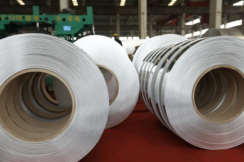
I. Functional Role of Aluminum Foil in Fuse Components
Aluminum foil serves the following primary functions within fuse components:
1. Fuse Element Function
Fuses operate based on the “Joule heating + metallurgical fusing” principle. When current exceeds the rated value, the fuse element heats up to its melting point and melts to interrupt the circuit. Aluminum has a melting point of ~660 °C and a density of 2.70 g/cm³—only ~30% that of copper (8.96 g/cm³). At equal mass, aluminum enables longer or wider fuse element geometries, thereby improving current interruption characteristics.
2. Current Collection and Electrical Connection Function
In high-current fuses (e.g., battery pack fuses and power distribution unit [PDU] fuses), aluminum foil is electrically connected to copper terminals or busbars via ultrasonic welding or laser welding—serving as both current collector and conductor.
3. Heat Dissipation and Temperature Rise Control Function
Aluminum exhibits a thermal conductivity of ~237 W/(m·K). Joule heat generated during prolonged fuse operation is rapidly dissipated through the aluminum foil to the housing and terminals, reducing temperature rise and enhancing fuse service life and I²t characteristic stability.
4. Mechanical Support and Packaging Function
In intelligent fuses equipped with fuse indicators (e.g., strikers or indicators), aluminum foil may serve as a structural support or carrier for sensing circuits.
II. Critical Performance Indicators for Aluminum Foil Used in Fuses
2.1 Chemical Composition and Fusing Characteristics
Recommended industrial-purity aluminum grades include 1060 / 1050 / 1145 / 1235, with minimum aluminum content ≥ 99.0% (compliant with ASTM B479 / GB/T 3190). Typical tempers: O (annealed), H14, H18, H22, and H24.
Typical chemical composition and application of commonly used aluminum foil grades:
| Grade | Minimum Al Content | Key Impurity Limits (Si / Fe / Cu) | Typical Temper | Typical Application |
|---|---|---|---|---|
| 1050 | 99.50% | Si ≤ 0.25% / Fe ≤ 0.40% / Cu ≤ 0.05% | O / H14 / H18 | Low-voltage distribution fuses, busbars |
| 1060 | 99.60% | Si ≤ 0.25% / Fe ≤ 0.35% / Cu ≤ 0.05% | O / H14 / H18 | New-energy vehicle battery pack fuses |
| 1145 | 99.45% | Si ≤ 0.55% (Si+Fe) / Cu ≤ 0.05% | O / H18 | Rail transit traction fuses |
| 1235 | 99.35% | Si ≤ 0.65% (Si+Fe) / Cu ≤ 0.05% | O / H14 | Photovoltaic string fuses |
The resistivity of aluminum at 20 °C is ~2.65×10⁻⁸ Ω·m, corresponding to an electrical conductivity of ~61% IACS. Relative to copper (100% IACS), aluminum delivers ~60% of copper’s conductivity at equal cross-sectional area; therefore, fuse design must compensate via increased cross-section or reduced thickness.
Impurity control requirements: silicon (Si) ≤ 0.25%, iron (Fe) ≤ 0.40%, copper (Cu) ≤ 0.05%, zinc (Zn) ≤ 0.05%, manganese (Mn) ≤ 0.05%. Excessive impurities degrade resistance uniformity, fusing time consistency, and long-term stability.
2.2 Dimensional Accuracy
Aluminum foil thickness for fuse applications typically ranges from 0.020–0.300 mm. Thickness specifications by application:
- Low-voltage fuse elements: 0.020–0.080 mm, tolerance ±5%
- New-energy vehicle battery pack fuse current-collecting foil: 0.050–0.150 mm, tolerance ±3%
- PV string fuse elements: 0.050–0.200 mm, tolerance ±4%
- High-current industrial fuse busbar foil: 0.150–0.300 mm, tolerance ±3%
Thickness tolerance directly affects the fuse’s I²t characteristics, pre-arcing time, and interruption capability. Width tolerance is generally maintained within ±0.05 mm, while coil length is customized per customer requirement.
2.3 Surface Condition and Processing Technology
Fuses impose strict requirements on the surface condition of aluminum foil. The naturally formed aluminum oxide (Al₂O₃) layer on bare aluminum foil has a thickness of approximately 2–10 nm, which increases contact resistance and compromises consistency in fusing characteristics. Common surface treatment processes include: chemical polishing or mechanical polishing to reduce surface roughness (Ra ≤ 0.5 μm); nickel plating (Ni: 2–5 μm) to improve solderability and oxidation resistance; copper plating (Cu: 1–3 μm) to enhance connection reliability with copper terminals; and tin plating (Sn: 1–3 μm), suitable for applications operating at lower temperatures.
For precision fuses requiring low contact resistance, copper-clad aluminum (CCA) composite foil may be adopted—retaining aluminum’s low density advantage while delivering copper’s low contact resistance performance.
2.4 Mechanical and Fusing Performance
The mechanical properties of aluminum foil are closely correlated with its fusing behavior. Typical mechanical properties and corresponding fuse applications for commonly used tempers are as follows:
| Temper | Tensile Strength | Elongation | Hardness HV | Typical Fuse Applications |
|---|---|---|---|---|
| O (annealed) | 60–95 MPa | ≥ 25% | ≤ 25 | Miniature fuses, precision fuse element stamping |
| H14 (half-hard) | 95–135 MPa | 6–12% | 30–40 | New energy vehicle battery PACKs, energy storage battery modules |
| H22 | 90–130 MPa | 8–15% | 28–38 | Photovoltaic string fuses (moderate formability) |
| H24 | 120–160 MPa | 5–10% | 35–45 | Low-voltage distribution fuses |
| H18 (hard) | ≥ 140 MPa | ≤ 5% | ≥ 45 | Rail traction fuses (high strength requirement) |
Key performance indicators for fusing behavior:
- Heat of fusion ≈ 397 J/g (aluminum) vs. 209 J/g (copper)—aluminum’s higher heat of fusion implies greater energy required to melt per unit mass;
- I²t characteristic (melting integral) is governed by fuse element cross-sectional area, length, and resistivity;
- Interrupting rating (D) shall range from 10–100 kA, depending on fuse class;
- Long-term temperature rise under rated current must comply with UL 248 and IEC 60269 standards.
III. Aluminum Foil Selection for Typical Fuse Application Scenarios
3.1 Battery PACK Fuses for New Energy Vehicles (High-Voltage 400 V / 800 V)
Operating conditions: DC high-voltage interruption, vibration environment, space-constrained packaging, low contact resistance and high reliability required. Recommended specifications: Material—1060-O annealed aluminum foil; thickness—0.050–0.150 mm; surface—nickel-plated (2–3 μm); width tolerance—±0.03 mm; compliant with GB/T 31465, ISO 8820, and UL 248.
3.2 Photovoltaic String Fuses (DC 1500 V)
Operating conditions: Outdoor exposure, wide ambient temperature swing, UV radiation, long-term DC loading. Recommended specifications: Material—1050 or 1235 aluminum foil; thickness—0.050–0.200 mm; surface—chemically passivated or nickel-plated; long-term operating temperature range—–40 °C to +85 °C; compliant with IEC 60269-6 and UL 2579 photovoltaic fuse standards.
3.3 Battery Module Fuses for Energy Storage Systems
Operating conditions: High-current operation (hundreds to thousands of amperes), frequent charge/discharge cycling, stringent thermal management requirements. Recommended specifications: Material—1060-H14 half-hard aluminum foil; thickness—0.100–0.300 mm; joint method—ultrasonic welding or laser welding to copper terminals; compliant with GB/T 36276 and UL 1973 energy storage system standards.
3.4 Low-Voltage Distribution Fuses (gG / aM Types)
Operating conditions: AC 400 V / 690 V, panel-mounted installation, interrupting rating ≥ 100 kA required. Recommended specifications: Material—1050 aluminum foil or copper-clad aluminum (CCA) foil; thickness—0.080–0.200 mm; compliant with IEC 60269-1, -2, and -4.
3.5 Rail Traction Fuses
Operating conditions: High-frequency vibration, temperature cycling from –40 °C to +70 °C, 30-year reliability requirement. Recommended specifications: Material—1145-H18 hard temper aluminum foil; thickness—0.100–0.250 mm; surface—nickel-plated; compliant with IEC 60077 and EN 50121 rail transportation standards.
IV. Key Manufacturing Process Considerations for Fuse-Grade Aluminum Foil
4.1 Fuse Element Forming Process
The geometric configuration of the fuse element (“M-shaped”, “S-shaped”, or “V-shaped” narrow-neck design) directly determines its fusing characteristics. Common fabrication methods include:
- High-speed stamping (200–600 strokes per minute) for contour forming;
- Laser cutting for precision elements (e.g., 0.02 mm thickness);
- Etching for miniature fuses (e.g., surface-mount fuses).
Pre-stamping annealing is required to achieve optimal ductility (elongation ≥ 25% in O temper). Die clearance = 8–10% of aluminum foil thickness (per side); burr height ≤ 0.01 mm.
4.2 Welding Process Compatibility
Common joining processes for aluminum foil to copper terminals, aluminum busbars, and nickel foils include:
- Ultrasonic welding** — low temperature (< 300 °C), suitable for aluminum–copper dissimilar metal joining; weld strength ≥ 30 MPa;
- Laser welding** — localized high temperature (800–1500 °C), small weld spot, minimal heat-affected zone;
- Resistance welding** — instantaneous high current, applicable for thick aluminum foil to copper busbar joints;
- Cold crimping (crimp terminals)** — no heating required, mechanically reliable electrical connection.
Prior to welding, the native aluminum oxide layer on the foil surface must be removed via mechanical scraping, chemical cleaning, or ultrasonic-assisted fluxing.
4.3 Surface Insulation and Packaging
Insulation treatment is required in the fuse element region: epoxy resin coating (UL94 V-0 flame-retardant rating), ceramic housing encapsulation, localized wrapping with polyimide (PI) tape, or molding compound (EMC) potting.
V. Typical Failure Modes and Mechanism Analysis
5.1 Fuse Element Aging and I²t Drift
Failure phenomenon: Drift in rated breaking current and change in I²t characteristics after prolonged service life. Failure mechanism: Electromigration and thermal fatigue of aluminum foil under repeated pulsed current, leading to localized reduction in cross-sectional area and increased resistance. Improvement measures: Use high-purity aluminum (≥ 99.5%); optimize fuse geometry to avoid local current density concentration; conduct periodic preventive fuse testing.
5.2 Increased Contact Resistance
Failure phenomenon: Excessive temperature rise at terminals and elevated voltage drop. Failure mechanism: Thickening of aluminum oxide layer (natural oxidation + electrochemical oxidation) and poor interfacial contact. Improvement measures: Apply nickel or copper plating (1–3 μm) on aluminum foil surface; substitute bare aluminum foil with copper-clad aluminum (CCA) foil; employ ultrasonic welding or cold crimping at terminal joints.
5.3 Incomplete Fuse Element Melting
Failure phenomenon: Failure to fully interrupt circuit during overcurrent events, resulting in sustained arcing. Failure mechanism: Exceeding thickness tolerance causing localized undersized cross-section; manufacturing defects (burrs, notches) in the fuse element; segregation of impurity elements forming low-melting-point eutectics. Improvement measures: Strictly control aluminum foil thickness tolerance (±3%); optimize stamping process to minimize burr formation; select 4N-grade (99.99%) high-purity aluminum.
5.4 Vibration Fatigue Fracture
Failure phenomenon: Fuse element fracture in rail transit or automotive fuses subjected to long-term vibration. Failure mechanism: Low elongation of hard-temper aluminum foil (≤ 5%), enabling fatigue crack propagation under vibrational stress. Improvement measures: Select H14 half-hard temper aluminum foil (elongation ≥ 6%); enhance fuse mounting structure with vibration-damping design.
5.5 Electrochemical Corrosion
Failure phenomenon: White corrosion products (hydrated aluminum oxide) observed on terminals of outdoor or high-humidity environment fuses. Failure mechanism: Galvanic corrosion between aluminum foil and dissimilar metals (e.g., copper terminals) in humid conditions. Improvement measures: Implement electrical insulation isolation at aluminum–copper interfaces; adopt copper-clad aluminum (CCA) foil to reduce dissimilar metal contact; upgrade fuse IP rating to IP65.
VI. Technical Evaluation Criteria for Aluminum Foil Suppliers
When selecting aluminum foil suppliers, fuse manufacturers are advised to conduct systematic evaluation across the following dimensions:
- Material traceability system**: Does the supplier provide complete Mill Test Certificate (MTC) per batch? Can material origin be traced back to ingot source and melting batch?
- Dimensional precision control capability**: Actual control level and Cpk value for thickness tolerance, width tolerance, and coil length tolerance;
- Surface consistency**: Coating thickness uniformity (CV ≤ 10%), surface roughness Ra value, and uniformity of chemical passivation film;
- International certification completeness**: ISO 9001, ISO 14001, and ISO 45001 system certifications; UL, RoHS, and REACH product certifications;
- Fuse-specific certification expertise**: Familiarity with fuse standards including UL 248, IEC 60269, ISO 8820, and GB/T 31465;
- R&D and customization capability**: Support for small-batch customization (minimum thickness 0.02 mm, non-standard widths, specialized coatings)? R&D response cycle duration?
- Supply chain stability**: Geographic distribution of production bases, minimum order quantity (MOQ), lead time, and inventory assurance strategy.
VII. Technical Specifications Overview (LP Industry)
Zhengzhou LP Industry Co., Ltd. specializes in R&D and manufacturing of magnet wire and metal foil materials. Its products are exported to over 50 countries and regions, backed by 30 years of industry experience.
For fuse component applications, LP Industry offers aluminum foil with the following technical specifications:
- Alloy grades: 1050 / 1060 / 1145 / 1235 industrial pure aluminum;
- Aluminum content: ≥ 99.0% (customizable to 99.5% / 99.9%);
- Electrical conductivity: ≥ 61% IACS (annealed condition at 20 °C);
- Thickness range: 0.020–0.300 mm;
- Thickness tolerance: ±3% / ±4% / ±5% (as specified by customer);
- Width range: 5–600 mm;
- Surface treatments: bare aluminum, nickel-plated, copper-plated, tin-plated, chemically passivated, or copper-clad aluminum (CCA) composite foil;
- Mechanical tempers: O (annealed soft temper), H14, H22, H24, H18;
- Compliance: ASTM B479, IEC, GB, JIS, NEMA, and other international standards;
- System certifications: ISO 9001, ISO 14001, ISO 45001 (SGS-audited);
- Product certifications: UL, RoHS compliance, REACH compliance.
LP Industry supports small-batch customization and joint R&D for new fuse models, with an R&D response cycle of 7–15 days.
Contact Information:
- Email: office@cnlpzz.com
- WhatsApp: +86-19337889070
VIII. Conclusion
The long-term reliability and fusing characteristics of fuse elements are jointly determined by three critical factors: fuse material, geometric structure, and interconnection process. Aluminum foil serves as a cost-effective alternative to copper-based materials, offering significant advantages in cost and weight reduction for application scenarios including new energy systems, photovoltaic and energy storage systems, low-voltage power distribution, and rail transit.
During material selection, a systematic evaluation must be conducted—based on the operational conditions of the specific application scenario (e.g., voltage rating, interrupting capacity, current loading, ambient medium, and vibration conditions)—and aligned with process compatibility requirements for fuse forming, welding interconnection, and surface treatment.
LP Industry leverages 30 years of R&D and manufacturing expertise in magnet wire and metal foil to provide fuse manufacturers with end-to-end technical support—from material selection and sample testing to mass production supply. Technical consultation and sample request are welcome.