

Introduction
What ECCA Magnet Wire Is and Where It Fits in the Industry
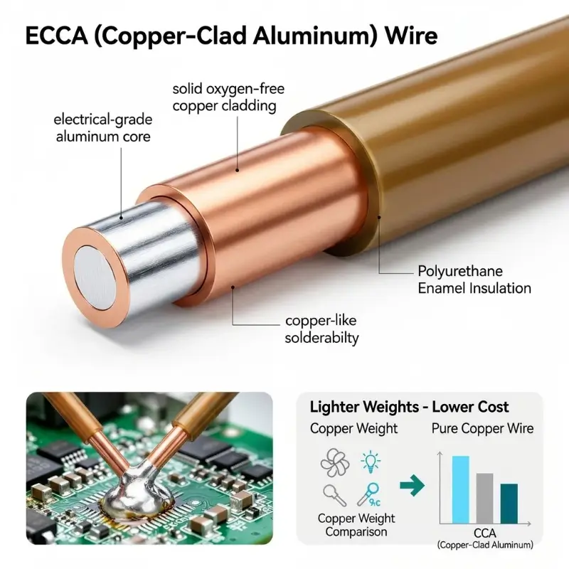
ECCA (Enamel-Coated Copper-Clad Aluminum Wire) is an electromagnetic wire product using a copper-clad aluminum composite conductor coated with an insulating enamel film. Structurally, it consists of three layers: an aluminum core, a copper cladding, and an insulating enamel film. The aluminum core provides advantages in terms of lightweight and low cost, the copper cladding provides reliable electrical contact surfaces and solderability, and the enamel film provides electrical insulation and mechanical protection between winding turns. While retaining the cost advantages of the aluminum core, ECCA wire overcomes the inherent defects of pure aluminum enameled wire in terms of contact reliability and solderability through the copper cladding.
How ECCA Magnet Wire Differs from Pure Copper, Pure Aluminum and Bare Copper-Clad Aluminum Wire
ECCA magnetic wire differs fundamentally from pure copper enameled wire, pure aluminum enameled wire, and bare copper-clad aluminum wire. Compared to pure copper enameled wire, ECCA magnetic wire uses an aluminum core, resulting in weight and cost reductions of approximately 40% to 60% and material costs of approximately 30% to 50%. Compared to pure aluminum enameled wire, the copper cladding of ECCA magnetic wire ensures reliable electrical contact and solderability, and its termination process is compatible with pure copper enameled wire, eliminating the need for aluminum-specific solder paste or ultrasonic welding equipment. Compared to bare copper-clad aluminum wire, ECCA magnetic wire has an added insulating varnish layer, allowing it to be directly used for winding. The applicable standard for bare copper-clad aluminum wire is ASTM B566, while the varnish performance of enameled ECCA magnetic wire is assessed separately according to the IEC 60317 system; the two should not be used interchangeably.
Scope of This Article and Intended Readers
This article focuses on the ECCA magnetic wire topic, systematically elaborating on the composite conductor structure and manufacturing process, key performance parameters, typical application areas, design and selection considerations, the impact of manufacturing process on performance, and quality inspection and reliability assessment. It aims to provide a technical framework for motor design engineers, transformer design engineers, power supply engineers, procurement technical evaluation personnel, and standards certification personnel.
ECCA Magnet Wire Structure and Manufacturing Process
Principle of the Bimetallic Composite Conductor Structure
ECCA wires have a conductor cross-section consisting of a concentric aluminum core and a copper cladding, with the copper layer comprising 10% or 15% of the total cross-sectional area. The aluminum core is typically made of electrical grade C11000 or copper-reinforced C13500, while the copper cladding uses oxygen-free copper. An intermetallic compound transition layer is formed between the copper layer and the aluminum core through electroplating or metallurgical bonding processes, achieving a permanent and continuous bond. ASTM B566 mandates this bonding condition, requiring that the finished wires be free of gaps or cracks, delamination of the cladding, and spliced joints.
Engineering Significance of the Copper-to-Aluminum Ratio
The copper-clad aluminum ratio is one of the most important engineering parameters for ECCA wire. The 10/90 ratio is the most commonly used standard ratio, with a combined density of approximately 3.4 g/cm³ to 3.6 g/cm³, a weight of 40% to 60% of pure copper wire, and a combined conductivity of 62% to 72% IACS of pure copper wire. The 15/85 ratio is used for applications requiring higher conductivity, with a combined conductivity of approximately 69% to 71% IACS. On a 0.500 mm diameter wire, a 10% copper layer corresponds to a radial thickness of approximately 0.013 mm, and a 15% copper layer corresponds to approximately 0.020 mm. Although the radial thickness of the copper layer is thin, it must withstand the full mechanical loads of drawing, coating, winding, slotting, and terminal crimping. The ratio selection should be based on a comprehensive trade-off between conductivity requirements, weight requirements, cost constraints, and high-frequency skin effect.
Manufacturing Processes for Copper-Clad Aluminum Billet
The manufacturing processes for copper-clad aluminum busbars mainly include casting, electroplating, and cladding welding. Casting involves continuous casting to solidify a copper layer outside the aluminum core, forming a metallurgical bond at the interface. This bond has high strength and stable conductivity, making it suitable for large-scale production of high-quality ECCA magnetic wires. Electroplating deposits a copper layer on the aluminum core surface through electrodeposition. The copper layer thickness is precisely controllable, but the interface bonding strength is lower than that of casting. Clad welding offers flexibility, but the weld interface affects long-term reliability. Composite drawing is a common subsequent process for all three methods. Due to the significant difference in flow stress between copper and aluminum, the deformation during drawing is inconsistent. Improper control of the process window can lead to longitudinal cracks in the copper layer.
Choosing Between Annealed and Hard-Drawn Tempers
Based on material condition, ASTM B566 classifies copper-clad aluminum wire into annealed (Type A) and hard-drawn (Type H) states. Annealed wire undergoes recrystallization at a specified temperature, eliminating work hardening and achieving good ductility, making it suitable for applications requiring multiple bends and deep groove winding. Hard-drawn wire skips the softening step, relying on cold working for strengthening; it has high strength but reduced ductility, although its tensile strength can be 30% to 50% higher than the annealed state of the same specification. The choice of state should directly match the winding forming process path.
Enamel Coating Process and Thermal Class System
The coating process for ECCA magnetic wires is consistent with that of traditional enameled wires, mainly including felt coating, mold coating, and electrostatic coating. The coated film needs to be baked for curing; the baking temperature and time depend on the enamel base system. The baking temperature for polyester enamel is 250°C to 350°C; for polyesterimide enamel, 280°C to 400°C; and for polyamide-imide enamel, 300°C to 420°C. The film thickness is typically controlled between 10 μm and 70 μm, depending on the wire diameter and heat resistance requirements. The enamel is classified into three grades: Grade 1, Grade 2, and Grade 3, according to insulation thickness, with thickness deviations controlled within ±10%.
Key Performance Parameters of ECCA Magnet Wire
Volume Resistivity and Conductivity
The volume resistivity of ECCA magnetic wires falls between that of pure copper and pure aluminum, depending on the copper-clad aluminum ratio. A 10/90 ratio results in a volume resistivity of approximately 2.74 μΩ·cm to 2.80 μΩ·cm and a conductivity of approximately 62% to 64% IACS. A 15/85 ratio results in approximately 2.45 μΩ·cm to 2.50 μΩ·cm and a conductivity of approximately 69% to 71% IACS. A 20/80 ratio results in approximately 2.20 μΩ·cm and a conductivity of approximately 76% IACS. Conductivity decreases linearly with increasing temperature. Under power frequency conditions of 50 Hz to 60 Hz, the skin effect is negligible, and the disadvantage in DC resistance directly manifests as increased copper losses and decreased efficiency in the motor.
Skin Effect and Current-Carrying Capacity at High Frequency
In the frequency range above 5 MHz, due to the skin effect, the current concentrates in the outermost layer of the conductor, and the outermost layer of ECCA wire is precisely a copper layer. At this point, almost all the current flows through the copper layer, and the current-carrying capacity is close to that of solid pure copper enameled wire. The resistance difference is significantly compressed in the frequency band above 5 MHz. This characteristic gives ECCA wire a substantial advantage in high-frequency winding applications such as wireless charging coils, high-frequency power transformers, RF inductors, and reactors, and also explains the economic advantage of ECCA wire over pure copper enameled wire in the 10 kHz to 100 kHz range.
Density and Weight Advantage
The density advantage of ECCA wire is the core driving force behind its industrial applications. The density of a 10/90 ratio wire is approximately 3.63 g/cm³, compared to 8.96 g/cm³ for pure copper enameled wire and 2.70 g/cm³ for pure aluminum enameled wire. For the same wire diameter, ECCA wire weighs approximately 40% of pure copper enameled wire. In transformer windings, this can reduce the total weight of the transformer by 12% to 20%; in motor windings, it can reduce the total weight of the motor by 15% to 25%. Winding weight typically accounts for 8% to 15% of the total weight of industrial motors, and this proportion can be further increased in new energy drive motors due to their higher winding density and longer length requirements.
Tensile Strength and Elongation
The mechanical properties of ECCA wire are dominated by the aluminum core, with the copper layer providing surface strength. The tensile strength (10/90 ratio) ranges from 80 MPa to 130 MPa, and the elongation is between 10% and 25%. This is significantly lower than that of pure copper enameled wire (tensile strength 220 MPa to 280 MPa, elongation 5% to 15%), but slightly higher than that of pure aluminum enameled wire (tensile strength 70 MPa to 110 MPa, elongation 8% to 20%). In terms of elongation, ECCA wire is superior to pure copper enameled wire, exhibiting good winding and processing performance. When selecting ECCA wire, attention should be paid to the strength margin, as winding tension, slotting extrusion, and terminal crimping deformation all consume mechanical margins; in engineering applications, a margin of approximately 30% is advisable.
Solderability and Termination Reliability
ECCA wire exhibits superior solderability compared to pure aluminum enameled wire, and is comparable to pure copper enameled wire. The copper cladding provides a reliable solder contact surface, allowing for good wetting with conventional tin-lead or lead-free solders at temperatures ranging from 350°C to 380°C. Termination reliability depends on the integrity and uniformity of the copper layer, as well as the control of soldering temperature and time. A copper layer that is too thin (below 30 μm) may melt during soldering; a minimum thickness of 50 μm is recommended to ensure soldering reliability. Crimping terminations use mechanical pressure to create a hermetically sealed contact between the copper cladding and the terminal, requiring high precision in copper layer thickness and uniformity.
Intermetallic Compound Growth and Thermal Stability at the Interface
The main risks faced by ECCA wires are the oxidation and electrochemical corrosion of aluminum at the interface. During thermal aging, intermetallic compound layers such as CuAl₂, CuAl, Cu₄Al₃, and Cu₉Al₄ thicken with temperature and time, increasing intermetallic resistance and causing localized heating. The growth of intermetallic compounds follows Arrhenius kinetics, with the aging rate roughly doubling for every 10°C increase in temperature. Windings operating long-term at a thermal rating of 180°C may exhibit resistivity drift after thousands of hours if the initial interface condition is not ideal. This phenomenon does not occur in pure copper enameled wires; therefore, interface quality should be controlled as an independent indicator.
Abrasion Resistance and Surface Integrity
During the winding process, enameled wire must withstand friction with the slot insulation, slot wedges, and winding tools. The copper layer surface of ECCA magnetic wire is relatively soft, and its scratch resistance is weaker than that of pure copper enameled wire, which is particularly noticeable on high-rate production lines with automated winding. This needs to be compensated for by controlling the winding tension, slot insulation material, and winding process. The continuity of the enamel film should be confirmed by pinhole inspection; the absence of pinholes and peeling are the criteria for acceptance.
Typical Application Areas for ECCA Magnet Wire
Auxiliary and Lightweight Motors in Electric Vehicles
The auxiliary motors of new energy vehicles represent the most representative application of ECCA magnetic wire. While drive motors are used in large quantities and are weight-sensitive, auxiliary motors, such as those for windshields, wipers, seat adjustments, and power steering pumps, are even more cost-sensitive. Using ECCA magnetic wire instead of pure copper enameled wire achieves a balance between cost and weight. This application typically requires a heat rating of 155°C to 180°C and employs a solderable polyurethane coating to simplify terminal connection procedures.
High-Frequency Power Supplies and Wireless Power Transfer
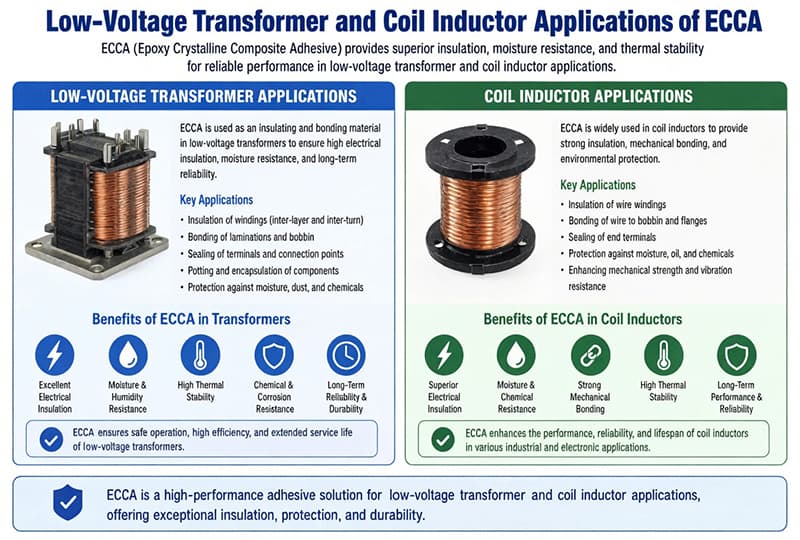
Wireless charging transmitter and receiver coils, high-frequency switching power supply transformers, and RF inductors and reactors belong to the high-frequency application family of ECCA magnetic wires. In these scenarios, the equivalent characteristics of high-frequency current carrying capacity above 5 MHz, which are close to those of pure copper enameled wire, constitute a decisive advantage. The winding design is based on the matching relationship between skin depth and copper layer thickness. Insufficient copper layer thickness will result in the effective conductive cross-section not being able to cover the skin depth.
Audio Equipment and Loudspeaker Voice Coils
Speaker voice coils, car amplifier coils, and subwoofer coils require a large number of thin, long wires, making them sensitive to weight and cost. ECCA wire reduces overall weight while maintaining soldering reliability. Voice coil winding requires high uniformity of wire diameter and abrasion resistance of the enamel film, and Grade 2 and Grade 3 enamel film thicknesses are commonly used in these applications.
Household Appliances and Small and Medium Motors
Household appliance motors and small to medium-sized motors are the main application areas for ECCA magnetic wires. These applications typically operate within the power frequency range, and the selection criteria are primarily cost and weight rather than high-frequency characteristics. Therefore, a 10/90 ratio modified polyester coating with a thermal rating of 155°C offers optimal economic efficiency. These applications are sensitive to continuous operating temperature rise, and the additional temperature rise caused by interfacial resistance drift should be factored into the thermal design margin.
Coils for Electronic and Communication Equipment
Common-mode chokes, relay coils, solenoid valve coils, miniature transformers, and sensor windings fall into the category of low-volume, high-density applications. These windings require a small amount of wire but need to accommodate as many turns as possible within a limited space. The cross-sectional fill rate advantage and miniaturization capabilities of ECCA magnetic wires are particularly valuable in these applications.
Design and Selection Considerations
Matching Skin Depth Against Copper Layer Thickness
The high-frequency performance advantage of ECCA wires relies on the premise that the copper layer thickness can cover the skin depth. The skin depth decreases with increasing frequency; the higher the frequency, the stronger the current concentration on the conductor surface, and the more stringent the requirement for the minimum copper layer thickness. When the copper layer thickness is less than the skin depth at the corresponding frequency, the current will penetrate to the copper-aluminum interface, and the interface resistance and intermetallic compound layer will enter the conductive path, thus eliminating the high-frequency advantage. Therefore, the selection of ECCA wires for high-frequency applications must simultaneously verify the matching relationship between the copper layer thickness and the operating frequency.
Impact of Copper Layer Integrity on Long-Term Reliability
Copper layer integrity is a core factor in the long-term reliability of ECCA magnetic wires. Localized missing copper layers, uneven thickness, interface defects, or copper layer peeling can lead to failure modes such as excessively high local current density, localized overheating, and interface corrosion. Copper layer integrity is affected by multiple factors, including busbar manufacturing processes, pretreatment before enamel coating, and enamel baking temperature. During long-term operation, Kirkendal effect voids may form at the interface between the copper layer and the aluminum core under high temperature and humidity conditions, affecting the interface bonding strength. The design and selection should strictly control the uniformity of copper layer thickness, with a deviation not exceeding ±10%.
Termination Process Design
The termination process design of ECCA magnetic wire is a crucial consideration in wire selection. Soldering is the most common method, with a copper cladding thickness of at least 50 μm to ensure weld reliability. An excessively thin copper layer is easily melted by the solder during welding, exposing the aluminum core. Crimping termination uses mechanical pressure to create an airtight contact between the copper cladding and the terminal, requiring high copper layer thickness and uniformity. Wrapping termination is suitable for small wire diameter applications, while bolted termination is used for high current applications. The termination process should be selected based on current density, vibration conditions, and temperature environment.
Pre-Treatment Before Coating and Adhesion Control
Pre-treatment before coating has a significant impact on the adhesion and dielectric properties of the enamel film on ECCA magnetic wires. Pre-treatment includes cleaning, annealing, and surface activation. Cleaning removes oil, oxide layers, and impurities from the copper surface. Annealing eliminates internal stress during the drawing process, improving elongation and bending workability. Surface activation increases the surface energy of the copper layer through chemical or physical methods, enhancing enamel film adhesion. Insufficient pre-treatment quality leads to decreased enamel film adhesion, making the wire prone to peeling and pinhole expansion during winding and thermal cycling.
Standards and Certification Framework
The design and procurement of ECCA wire should refer to relevant standards. ASTM B566 specifies the grade classification, resistivity, density, tensile strength, elongation, and mandatory requirements for interfacial bonding of bare round copper-clad aluminum wire, serving as the fundamental standard for the conductor layer. The IEC 60317 series of standards specifies the enamel coating types, temperature ratings, dimensions, and test methods for enameled wires, with IEC 60317-0-1 providing general requirements, and each volume corresponding to a specific enamel base system. NEMA MW 35-C specifies the naming, dimensions, and performance requirements for copper-clad aluminum enameled wires, while NEMA MW 1000 covers enamel coating thickness grades (Grade 1/2/3), test methods, and marking rules. UL 1446 specifies the method for evaluating the heat resistance rating of electrical insulation systems. When procuring, it is advisable to request material data sheets, UL documents, and third-party reports.
How Manufacturing Process Affects Performance
How Billet Process Differences Propagate into Reliability
The manufacturing process of copper-clad aluminum busbars significantly affects the performance of ECCA magnetic wires. The casting method involves continuously casting a copper layer onto the aluminum core, forming an intermetallic compound transition layer at the interface. This results in high bonding strength and stable conductivity, making it suitable for large-scale production of high-quality ECCA magnetic wires. The electroplating method involves electrodepositing a copper layer onto the aluminum core surface, allowing for precise control of the copper layer thickness, but the interfacial bonding strength is lower than that of the casting method. The cladding and welding method uses copper strip cladding and welding to form a composite structure, offering flexibility, but the weld interface affects long-term reliability. Insufficient interfacial bonding strength will cause the copper layer to separate from the aluminum core under bending, vibration, and thermal cycling.
Methods for Evaluating Interface Bond Strength
Interfacial bond strength is assessed through peel or pull-out tests. For cast copper-clad aluminum, this ranges from 30 N/cm to 50 N/cm, while for electroplated copper-clad aluminum, it ranges from 20 N/cm to 35 N/cm. The peel test involves peeling the copper layer from the aluminum core and recording the peel force required per unit width. The pull-out test stretches the entire ECCA wire until it breaks, assessing the fracture location and fracture strength. The bending test repeatedly bends the ECCA wire at a certain angle, observing whether the copper layer peels off or lifts. Interfacial bond strength tests should be performed under normal conditions and after accelerated aging. The passing standard is typically that the attenuation does not exceed 30% of the initial value.
Copper Layer Uniformity and Eccentricity Control
Copper layer thickness uniformity is a key indicator for quality control of ECCA magnetic wire. Ideally, ECCA magnetic wire should have a concentric circular cross-section, with the copper layer thickness remaining stable along both the circumferential and axial directions. Thickness deviation should be controlled within ±10%, and the copper layer coverage should be complete without any local defects. Cross-sectional eccentricity can cause microcracks on the weaker side under winding tension, which can propagate and form corrosion channels over long-term operation. Methods for measuring copper layer thickness include metallographic cross-section observation, X-ray fluorescence spectroscopy, eddy current method, and density method. Metallographic cross-section observation is an arbitration method, providing accurate results but is a destructive measurement; X-ray fluorescence spectroscopy is a non-destructive measurement, suitable for batch testing on production lines.
Enamel Thickness and Uniformity Control
The thickness and uniformity of the varnish film are key control points for the electrical and mechanical properties of ECCA magnetic wires. The varnish film thickness should be designed according to the heat resistance grade and mechanical strength requirements, and the thickness deviation should be controlled within ±10%. The varnish film should be continuous, uniform, free of pinholes and peeling. Insufficient thickness will lead to a decrease in dielectric strength and failure of inter-turn insulation; excessive thickness will lead to an increase in overall diameter and occupy winding space.
Quality Inspection and Reliability Assessment
Electrical and Mechanical Testing of the Conductor
DC resistance and resistivity are measured according to ASTM B193 and converted to standard resistivity at 20°C. Tensile strength and elongation are also measured according to ASTM B193, with different requirements for different grades and wire diameters. Breakdown voltage is tested according to IEC 60851-6 or ASTM D149 to verify the insulation strength of the varnish film; the breakdown voltage at room temperature should not be less than 5 kV for a varnish film thickness of 30 μm. Pinhole detection is used to confirm the continuity of the varnish film. Thermal shock resistance and thermal aging are performed according to ASTM D2307.
Dielectric Performance and Dissipation Factor
The dielectric loss factor (tanδ) and dielectric breakdown voltage are the core evaluation indicators of the electrical performance of ECCA magnetic wires. The tanδ test is conducted at a frequency of 1 kHz. The tanδ for Class B varnish should be below 0.020, for Class F varnish below 0.015, and for Class H varnish below 0.010. High-temperature testing should be conducted under the rated heat resistance class, with the dielectric strength decreasing by no more than 30% and the tanδ increasing by no more than 50%.
Accelerated Aging and Thermal Life Assessment
Accelerated aging and thermal life assessment are core methods for predicting the long-term reliability of ECCA wires. Three test temperature levels are typically selected, with several samples placed at each temperature and key parameters measured periodically. Arrhenius regression analysis is performed on the data according to IEC 60216 standard to obtain the temperature index (TI) and life curves. The design life of Class B, F, and H ECCA wires at their corresponding rated temperatures should be no less than 20,000 hours. Given that intermetallic compound growth is a unique degradation mechanism for ECCA wires, the drift trend of interfacial resistance should also be monitored during life assessment.
Soldering Performance and Contact Resistance Testing
Solderability testing includes solder wettability testing, solder strength testing, and contact resistance testing. The solder wettability test involves immersing the end of the ECCA wire in a 350°C solder bath and observing the solder wetting process. The solder strength test involves stretching the soldered ECCA wire on a tensile testing machine. The contact resistance test measures the contact resistance of the solder joint; it should be less than 1 mΩ. Wetting time and solder joint strength are indirect means of assessing the integrity of the copper cladding.
Sampling and Incoming Inspection Control Points
Sampling shall be performed according to ANSI/ASQ Z1.4, with a standard AQL of 1.0 and general inspection level II. As ECCA magnetic wire is a composite material, incoming material inspection should include peel strength and copper layer thickness as mandatory items, and the conformity declaration should be verified batch by batch according to the ASTM B566 level corresponding to the copper-clad aluminum ratio and material condition. Sampling inspection should distinguish between busbar batches and enameled batches, avoiding substitution with inspection items for pure copper enameled wire.
Failure Modes Unique to Composite Conductors
In addition to the common failure modes of enameled wire (pinholes, enamel film cracks, and inter-turn short circuits), ECCA magnetic wire requires extra attention to three unique failure types. Interface delamination manifests as microcracks at the copper-aluminum interface caused by excessive winding tension or excessive compression within the slots. Corrosion occurs along these cracks in humid environments, leading to increased interfacial resistance and localized heating. Copper layer puncture occurs when the enamel film is locally scratched down to the copper layer, directly exposing the aluminum core to the electrolyte, resulting in a corrosion rate far faster than that of pure copper enameled wire. Electrochemical migration occurs under high humidity and ion contamination conditions, where aluminum acts as the anode, leading to accelerated dissolution, which is more pronounced in coastal and industrial corrosive environments.
Conclusion
ECCA magnetic wire is an electromagnetic wire product with a three-layer composite structure:
- Aluminum core, providing low weight and low material cost
- Copper cladding, providing a reliable contact surface and solder compatibility
- Enamel coating, providing turn-to-turn insulation and mechanical protection
This construction combines the contact reliability of copper with the lightweight and low-cost advantages of aluminum. Its conductivity is close to that of pure aluminum enameled wire, while its contact reliability and soldering processability are significantly superior. It weighs approximately 40% of pure copper enameled wire and costs approximately 55% to 70% of it. In frequency bands above 5 MHz, the skin effect causes current to flow primarily through the copper layer, resulting in a current-carrying capacity close to that of pure copper enameled wire.
Typical applications of ECCA magnetic wires cover the following fields:
- Auxiliary motors and lightweight motors in new energy vehicles
- High-frequency power supplies and wireless power transmission
- Audio equipment and loudspeaker voice coils
- Household appliances and small and medium-sized motors
- Coils in electronic and communication equipment
In high-frequency applications, ECCA magnetic wires have a decisive advantage; however, in the scenario of main motor windings for high-capacity main motors at industrial frequencies, the copper loss and temperature rise caused by the disadvantage of DC resistance are usually not economical.
The selection of ECCA magnetic wire should be based on a comprehensive decision across the following factors:
- Copper-to-aluminum ratio, which sets conductivity and weight
- Heat resistance rating, matched to the worst-case winding temperature
- Wire diameter, which governs slot fill and mechanical strength margin
- Termination process, which must suit the copper layer thickness
- Operating frequency, which determines whether the skin effect advantage applies
Copper layer integrity, interfacial bonding strength, and enamel quality are core factors for long-term reliability. During procurement, suppliers should be required to provide measured peel strength data and copper layer thickness distribution reports.
Engineering applications and procurement should be based on a scientific selection of ECCA magnetic wires according to their performance and application boundaries. In scenarios with strict requirements for high frequency, lightweight design, and cost sensitivity, ECCA magnetic wires have significant advantages. However, in scenarios with high power frequency current, extremely high mechanical strength requirements, long-term high temperature, and insufficient heat dissipation, the suitability of ECCA magnetic wires should be carefully evaluated, and pure copper enameled wires or other alternatives should be selected if necessary.