

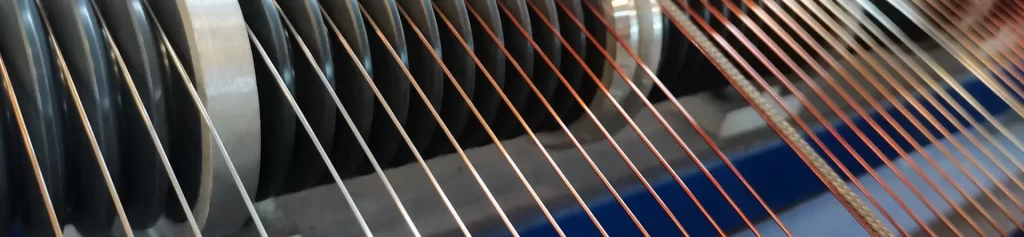
Copper wire with enamel coating is a fundamental material for motors, transformers, and various electromagnetic devices. The long-term stability of its insulation enamel coating at working temperature directly determines the usable lifespan of the equipment. The answer to the question “How long can this equipment continue to operate?” has long relied on two crude approaches: one is to directly treat the thermal class as the upper limit of the operating temperature, and the other is to directly treat the expected life given in the standard as the equipment life. The former ignores hot spots and load fluctuations, while the latter ignores the coupling differences between the insulation system and the overall assembly. Both lead to overly optimistic conclusions in long-term operation. The significance of thermal aging prediction lies in transforming “operating time” from an empirical estimate into an engineering conclusion with methodological basis. It doesn’t provide an absolute lifespan figure, but rather defines the preconditions for the prediction’s validity, the sources of error, and the criteria for determining failure. This paper, based on the IEC 60172, IEC 60216, and IEC 60085 standards, and incorporating the corresponding methods of NEMA MW 1000, IEEE Std 1, and ASTM D2307, systematically elucidates the physical basis, experimental methodology, grade correspondence, engineering correction methods, and decision-making framework for thermal aging prediction of enamel-coated copper wires.
Physical Mechanisms of Thermal Aging and Life Decay
Thermal Degradation Pathways of Organic Enamel Coatings
The insulation layer of the enamel-coated copper wire is composed of thermosetting organic polymers. Its thermal aging is not a single failure process, but rather the result of multiple degradation pathways superimposed on each other. The primary pathway is the oxidation breakage of the main chain and side chains. The enamel coating resin continuously undergoes oxidation reactions in the presence of oxygen, leading to an increase in carbonyl concentration and molecular chain breakage. This manifests as hardening of the enamel coating, loss of embrittlement, and loss of elasticity, with mechanical properties deteriorating before electrical properties. The second pathway involves the volatilization and migration of the plasticizer or unreacted components. Low-molecular-weight substances remaining from the enameling/curing stage escape under continuous heating, causing a redistribution of internal stress within the enamel coating and the appearance of micro-voids in the interface region. Thermal mechanical stress subsequently concentrates at these defect locations, initiating microcracks under the influence of thermal cycling. The third path is the adhesion decay between the enamel coating and the copper conductor interface. Residual oxidation at the interface, areas with insufficient pretreatment, and mechanical fatigue introduced by electromagnetic pulsations and vibrations during operation will gradually weaken the bonding force under the combined effects of heat and mechanical forces. When the adhesion decreases to a critical state, the enamel coating will peel off in sheets under mechanical disturbance, forming through-hole defects. All three pathways share the common premise of temperature. Chemical reaction rates follow the Arrhenius equation and are significantly dependent on absolute temperature. Therefore, the thermal class and enamel coating system together determine the upper limit of the aging rate, while the mechanical and chemical environment determines where the actual rate falls within that upper limit.
The Arrhenius Relation and the Ten-Degree Rule
The Arrhenius equation describes the relationship between the rate constant of a chemical reaction and absolute temperature, and takes a linear form when the logarithm is taken. This form allows the temperature-time characteristics of the heat resistance of the enamel coating to be represented by a straight line, which is the mathematical basis of the IEC 60172 temperature index determination method. In insulation material engineering practice, this leads to a widely used empirical rule, the ten-degree rule: within the material’s rated temperature range, for every 10°C increase in ambient temperature, the aging rate approximately doubles, and the corresponding service life is reduced by about half. This rule is an engineering approximation of the Arrhenius relationship, not an independent theory. The actual activation energy of the enamel coating varies with temperature range, material system, and formulation; therefore, the expression using 10°C increments and doubling the value is suitable for rapid estimation but not for precise calculation. It is important to note that the physical basis of the rule determines its applicable boundaries. As enamel coatings approach their decomposition temperature, the degradation mechanism may change, at which point the “lifespan halved for every 10°C increase” no longer holds true. For high-grade enamel coatings such as polyester-imides and polyamide-imides, this critical region typically occurs within tens of degrees Celsius above the rated temperature. Therefore, applying this rule to operating conditions beyond the thermal class will rapidly amplify the error. The true engineering value of the ten-degree rule lies in its sensitivity to temperature deviations rather than the absolute lifespan itself. When the actual operating temperature exceeds the expected value by 10°C, the lifespan is reduced by about half; exceeding it by 20°C, the lifespan is reduced to about a quarter. This non-linear amplification makes the design significance of the temperature allowance far beyond intuition—setting a 20°C margin results in four times the lifespan redundancy, not twice.
The Relationship Between Thermal Class and Standard Expected Life
IEC 60085 classifies insulation into nine grades—Y, A, E, B, F, H, N, R, and 250—based on the heat resistance of insulating materials under specified conditions. Each grade corresponds to a different maximum permissible continuous working temperature. NEMA MW 1000 does not use letter grades but directly uses Celsius temperature values to indicate the thermal class. The two systems are numerically compatible.
| IEC 60085 level | Maximum permissible continuous working temperature | NEMA MW 1000 corresponds to thermal class | Common enamel coating systems |
|---|---|---|---|
| E | 120 °C | 120 °C | Polyvinyl Formal (PVA), polyurethane |
| B | 130 °C | 130 °C | polyester, polyurethane |
| F | 155 °C | 155 °C | polyester, polyester polyester-imide |
| H | 180 °C | 180 °C | polyester-imide |
| N | 200 °C | 200 °C | polyamide-imide |
| R | 220 °C | 220 °C | polyamide-imide, dual coat |
| 250 | 250 °C | 240 °C / 250 °C | polyimide and its composite systems |
The standard provides a clearly defined expectation life. First, the expected life is the minimum guaranteed value under continuous operation at the rated temperature, not the upper limit of the equipment’s usable life; the life will be extended if the actual operating temperature is lower than the rated temperature. Second, this value describes the performance of the enamel coating as an independent material, excluding differences in heat distribution after winding is embedded in the slot, ventilation conditions within the slot, end fixing methods, and mechanical constraints. Third, the expected life is based on a single dominant aging mechanism; if significant mechanical stress or chemical corrosion is introduced during operation, the actual degradation will be faster than in a pure thermal aging model.
Methodology for Determining the IEC 60172 Temperature Index
Standard Scope and Specimen Preparation
IEC 60172 specifies the temperature index testing procedure for enamel-coated and wrapped wires, applicable to the method of assessing insulation life by periodically monitoring changes in AC voltage response in ambient air. This method is not applicable to fiber-insulated wires or wires containing inorganic fiber wrapping. Normative references to this standard are IEC 60216-1 for aging procedures and results evaluation methods, and IEC 60216-3 for thermal endurance characteristic calculation instructions. Specimen preparation is the primary step in the process to introduce errors. For enamel-coated round wires with nominal conductor diameters from 0.224 mm to 2.65 mm, the specimen is made by twisting approximately 400 mm of wire over a length of 125 mm, with torque and twisting turns as specified in Table 1 of the standard. Different diameter ranges correspond to different torques; for example, wires with diameters from 0.800 mm to 1.050 mm are subjected to a force of 13.5 N and twisted 8 times. After twisting, the specimen is shaped in a special fixture with spacers, and then the loop ends are cut to form an electroneg. For wrapped round wires and rectangular wires, a 150 mm straight section is taken and formed using glass fiber bundles. The consistency of parameters in the preparation of the specimen directly determines the validity of the regression results. If the number of turns or torque deviates from the specified value, the mechanical stress state subjected to the specimen will not conform to the standard, and the initial defect distribution experienced by the enamel coating during thermal exposure will change accordingly. Consequently, the measured life-temperature relationship will not represent the true characteristics of the product. All specimen must undergo a 1-second AC withstand voltage test before aging; the test voltage is determined based on the insulation thickness.
Aging Cycles and Failure Determination
The specimen undergoes a “thermal exposure—withstand voltage test” cycle in a forced ventilation oven, and the oven must be able to maintain the specimen temperature within ±2 °C of the selected exposure temperature. The exposure temperature range is typically 120 °C to 320 °C, with at least 10 specimen configured for each temperature point. Approximately 10 cycles are recommended per temperature point, with a minimum lifetime of over 5,000 hours at the lowest temperature point and at least 100 hours at the highest temperature point. Standard Table 3 provides recommendations for the number of cycle days selected based on the estimated temperature index; for example, when the estimated temperature index is 200 to 209 °C, each cycle should be 4 days at 200 °C and 1 day at 280 °C. The withstand voltage test uses a 50/60 Hz AC voltage with a peak factor of √2±5%. The test transformer power is no less than 500 VA, and the overcurrent detection threshold is set to 5 mA. After each cycle, the {spcimen} is cooled to room temperature before applying the withstand voltage test for 1 second. The failure time is determined using the midpoint method: the midpoint between the previous non-failure test and the current failure test is taken as the failure time of the specified specifier. If a specifier does not fail after 240 hours but fails after 252 hours, its failure time is recorded as 246 hours. This approach avoids the conservative or optimistic biases introduced by directly substituting discrete observation points into the regression data, and is the standard practice for statistical processing of discrete observation data such as high-temperature aging.
Regression Analysis and Linearity Criteria
The relationship between lifetime and temperature is modeled using the least squares method. A linear regression is performed with the logarithm of lifetime Y = log₁₀L as the dependent variable and the reciprocal of absolute temperature X = 1/T (K) as the independent variable, yielding Y = a + bX. The temperature index represents the extrapolation temperature of this regression line at the 20,000-hour lifetime line. A complete calculation example is provided in Appendix A of the standard. Linearity is determined by the correlation coefficient r; a value of r ≥ 0.95 indicates that the data exhibits linear characteristics. The fifth edition of the standard has included the correlation coefficient in the reporting requirements. This criterion has clear diagnostic significance for failures: if r is below 0.95, it indicates that the data may reflect multiple coexisting aging mechanisms, excessive testing errors, or inconsistent specimen preparation. In such cases, the results should not be directly adopted but should be addressed by increasing the temperature range or re-verifying the testing process. Besides the regression line, the arrangement of temperature points itself constitutes a key methodological constraint. The minimum exposure temperature is typically set approximately 20 °C below the expected temperature index, the failure time at the highest temperature point should be greater than 100 hours, and the interval between adjacent temperature points should not exceed 20 °C. Furthermore, data with fewer than 8 cycles or more than 20 cycles should not be used, as an overly narrow sample interval can lead to unstable regression slopes.
The North American System and Equivalent Methods
The IEEE Std 1 and ASTM D2307 referenced by NEMA MW 1000 are methodologically similar to IEC 60172, both based on the Arrhenius model and using the 20,000-hour extrapolation method to determine the temperature index. Therefore, the thermal life test data for the same enameled wire roll under the IEC system (Class F) and the NEMA system (155 °C thermal class) are, in principle, equivalent. The two systems differ in their standard organizational structure and naming conventions: IEC 60317 uses a structure of “general requirements standard + a single enameled coating system corresponding to a single sub-standard,” while NEMA MW 1000 integrates all product types by part volume using a single parent standard. This difference affects the verification path, not the thermal life evaluation conclusion.
Engineering Factors Affecting Prediction Accuracy
Hot Spot Temperature and Temperature Allowance
The winding is not situated within a uniform temperature field within a slot. Heat dissipation conditions differ between the bottom, opening, and coil end of the slot. The end region experiences lower temperatures due to better ventilation conditions, while localized hot spots may form near the bottom of the slot. The rated temperature of the insulation system defined in IEC 60034-1 refers to the highest working temperature that no part of the winding should exceed; this statement itself acknowledges the inevitability of hot spots. In motor design, a hot spot margin of 10 K to 15 K is typically used to cover manufacturing variations, load fluctuations, and ambient temperature changes. Substituting this margin into the ten-degree rule reveals a significant lifespan implication: a 10 K margin corresponds to approximately twice the lifespan redundancy, and a 15 K margin corresponds to approximately three times. This implies a quantifiable correspondence between the temperature allowance in the design phase and the lifespan commitment in the operational phase, rather than a vague conservatism based on engineering conventions.
Load Fluctuations and Thermal Cycling
The thermal aging model under continuous constant load conditions differs fundamentally from the actual aging process under intermittent or fluctuating load conditions. When the motor frequently starts and stops or the load changes periodically, the winding undergoes repeated temperature rise and cooling cycles, each cycle introducing thermal mechanical stress into the enamel coating and copper interface. The greater the temperature fluctuation amplitude and the higher the cycle frequency, the faster the interface defects initiation. This effect cannot be directly captured by the Arrhenius model because it describes the chemical reaction rate under isothermal conditions. In engineering, it is typically addressed by increasing the thermal margin or selecting an enamel coating system with superior thermomechanical properties, rather than introducing additional terms into the lifetime prediction model. This approach is conservative but aligns with the practical logic of winding insulation design.
Impregnation and Insulation System Coordination
VPI (Vibration Impregnation) is a standard process in winding manufacturing. Impregnation resin, together with the enamel coating, constitutes the actual insulation system. The function of impregnation is to fill gaps in slots and inter-turns, remove moisture, improve heat dissipation, and fix the winding position, thereby reducing the mechanical stress on the enamel coating. If the thermal stability of the impregnation resin itself is lower than the enamel coating grade, the system’s weakness shifts to the impregnation layer—in this case, even if the enamel coating is a grade 180 material, the overall lifespan of the machine is still limited by the grade 155 impregnation resin. The standard clearly states this. IEC 60172’s temperature index measurement procedure provides test paths for enamel coatings in both impregnation and non-impregnation states, but the data reflects the combined performance of the enamel coating and the impregnation agent. Elektrisola also explicitly states in its IEC 60172 thermal stability comparison data that the relevant data is for technical comparison only and cannot be used to predict the lifespan of wound products. This limitation is often overlooked in engineering practice, resulting in the misuse of material-level data as equipment-level conclusions.
Matching Enamel Coating Systems to Thermal Classes
Different enamel coating systems do not have the same actual thermal stability under the same thermal class. Polyester-imides dominate in Class 180 products, offering a good balance between cost and heat resistance; polyamide-imides are widely used in Class 200 and 220 products, offering higher upper limits of thermal stability but narrower processing windows; dual-layer composite coating structures bear the heat load through an outer heat-resistant resin, improving adhesion and mechanical strength in higher-grade products. The selection of the enamel coating grade must be verified in relation to the enamel coating system; it cannot be inferred solely from the labeled grade. For example, even with a grade of 180, there is a substantial difference in thermal shock resistance between a single layer of polyester-imide and a composite structure of polyester-imide and polyamide-imide; the latter can withstand temperatures above 200 °C without cracking. When selecting a coating, verifying the specific system composition is more meaningful than simply checking the grade number.
Decision Framework for Thermal Aging Life Prediction
Step 1: Define the prediction boundaries and objectives. Clarify whether the prediction targets the enameled wire material itself, the winding insulation system, or the entire equipment. The lifespan conclusions for these three are not interchangeable; material-level data cannot be directly extrapolated to the equipment level. At the same time, it should be confirmed whether the prediction output format is “thermal class—lifespan comparison” or “remaining life estimate under specific operating conditions.” The former is used for equipment selection, while the latter is used for maintenance decisions; their methodological foundations and data requirements differ. Step 2: Determine the operating temperature and its distribution. Collect actual operating temperature data, including full-load and partial-load conditions, steady-state and transient processes, ambient temperature range, and cooling conditions. If measured data is unavailable, the highest possible operating condition should be used as the predictive input, and this assumption should be explicitly recorded. The location and margin of the hot spot must be determined at this stage, directly impacting subsequent thermal class selection. Step 3: Select the thermal class and match it to the enamel coating system. Determine the thermal class using the temperature distribution plus a hot spot margin from Step 2 as the minimum constraint; this margin is typically 10 K to 15 K. After selecting the class, verify the specific enamel coating system composition, impregnation resin grade, and coating structure to confirm that there are no system bottlenecks. The compatibility and grade matching relationship between commonly used impregnation resins and enamel coatings must be confirmed simultaneously. Step 4: Establish or reference life baseline data. Prioritize using the measured temperature index from IEC 60172, as it is more representative than general grading tables. If only grading data is available, reference the standard expected life range and explain its material-level preconditions. For fluctuating load scenarios, add a thermal cycling assessment and incorporate the results into the margin values. For new materials or formulations without measured data, temperature index determination must be arranged. Step 5: Output the conclusions and indicate applicable conditions and uncertainties. The prediction conclusions must include the input conditions used, the source of the baseline data, the preconditions for model applicability, and the main sources of uncertainty. They must not be presented as a single lifetime figure. The conclusions should clearly indicate under what conditions the conclusions need to be re-evaluated, such as changes in load patterns, cooling conditions, or system impregnation.
Common Misconceptions in Life Prediction
The most common misconception is equating thermal class with the upper limit of operating temperature. In reality, thermal class is a classification identifier for insulation systems. The permissible operating temperature of equipment is also constrained by winding and temperature rise limits, hot spot margins, cooling methods, and derating rules. The difference between the two often lies in the actual difference in equipment life. The second misconception is treating the standard 20,000-hour expected life as the usable life of equipment. This value is the minimum guaranteed value for the material grade at the rated temperature and is based on isothermal conditions. Actual operating temperatures are usually lower than the rated temperature, resulting in a longer lifespan; however, mechanical stress, chemical environments, and thermal cycling can shorten it. Directly citing this figure without specifying operating conditions usually leads to conclusions that are not actionable. The third misconception is using the temperature index to directly predict the lifespan of wound products. The temperature index obtained from IEC 60172 describes the performance of a specified shape under specified test conditions. The heat distribution, mechanical constraints, and ventilation conditions within the winding slot differ systematically from these specifications, and both the standard-setting body and industry manufacturers have clearly pointed this out. The fourth misconception is ignoring the distribution of hot spots and treating the winding as an isothermal body. The temperature differences between the location within the slot, the coil end, and the slot opening are real and occur precisely in areas with strong mechanical constraints, where the thermal mechanical stress superposition effect is more pronounced. The fifth misconception is applying a constant-temperature lifetime model under fluctuating load conditions. In intermittent operation, frequent start-stop cycles, or periodic load changes, failure is often driven by thermal cycling rather than pure thermal degradation. In such cases, using the Arrhenius model (extrapolation) will overestimate the lifetime. The sixth misconception is that increasing the thermal class can solve all lifespan issues. However, upgrading the thermal class will simultaneously increase enamel coating costs, reduce processing flexibility, and may introduce compatibility problems with impregnation resins and slot insulation materials. If the root cause of lifespan issues lies in hot spot design, load management, or insufficient cooling capacity, simply upgrading the enamel coating level often will not improve the actual results. The seventh misconception is using the ten-degree rule for precise extrapolation. This rule is an engineering approximation, and its errors become significant when exceeding or approaching the material’s decomposition temperature range, and it does not account for the effects of aging mechanism switching. It is appropriate for rapid sensitivity analysis, but its application to life commitments exceeds its capabilities. The eighth misconception is ignoring the correspondence between thermal class and enamel coating systems. Products of the same class can exhibit substantial differences in thermal shock tolerance and adhesion performance under different systems. If only the class number is checked during selection without verifying the system composition, unexpected performance may occur under thermal cycling conditions.
Conclusion
The essence of thermal aging life prediction is to incorporate actual engineering variables into material-level conclusions within the material boundaries given by the Arrhenius relation, thereby obtaining a traceable, verifiable life assessment with clearly defined applicability. The temperature index measurement method provided by IEC 60172 establishes a comparable quantitative benchmark for this conversion process: through standardized specimen preparation, cyclic thermal exposure, midpoint failure determination based on discrete observations, 20,000 hours of extrapolation, and linearity control with a correlation coefficient r ≥ 0.95, it provides a horizontally comparable thermal life data foundation for winding wires from different manufacturers and different lots. However, methodological rigor cannot replace the accuracy of input conditions. The temperature index answers “how long the enamel coating can withstand constant temperature conditions,” while equipment life depends on “how long the winding can operate under actual temperature distribution, load fluctuations, mechanical constraints, and the combined effects of impregnation.” The gap between these two needs to be bridged item by item through hot spot analysis, thermal cycling assessment, and co-design of the insulation system. Therefore, the final conclusion of life prediction should not be an isolated number of years, but rather a set of conditions: data sources, model assumptions, uncertainty sources, and under what conditions a reassessment is required. For engineering practice, the most valuable predictive capability lies in the sensitivity to the quantification of margins. A 10 K hot spot margin corresponds to approximately twice the lifetime redundancy, and 20 K corresponds to approximately four times. This conversion transforms temperature trade-offs in the design phase into comparable lifetime calculations, rather than the vague conservatism of engineering practice. Similarly, the identification of three types of changes—fluctuating loads, operating condition shifts, and material replacements—constitutes the watershed for whether the predictive conclusions can be extended to the entire life cycle of the equipment. A truly robust insulation life management system ultimately does not rely on a single temperature index value, but rather on the continuous verification of assumptions at each stage of the prediction chain: the representativeness of the temperature index data, the rationality of the operating condition assumptions, the sufficiency of the margin values, and a mechanism for re-evaluating the conclusions after the operating conditions evolve. This methodological rather than numerical capability is the true significance of thermal aging prediction in equipment reliability engineering.