

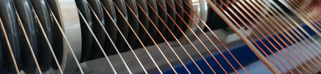
The reason why a motor burns out is often not because the customer thought, “the motor was used too harshly”.
Disassembling a scrapped motor reveals that the enamel coating on the copper wires may only be half the normal thickness, with pinholes as thin as needle points, and the insulation enamel coating appears as a dark, unrecognizable mass—these are the marks left by poor-quality enameled wire. These types of failures share a common characteristic: all incoming inspections arequalified (passed), and the motor also passed factory tests, but after six months to a year of operation, it suddenly burns out.
According to industry statistics, approximately 25%–36% of low-voltage motor failures are directly caused by insulation failure. In other words, in one out of every three motor burnout incidents, the insulation of the motor itself needs to be investigated.
The problem is that this process is too quiet. The enamel coating defect shows no outward signs at the factory; it’s contained within the slot, sealed by impregnation paint, and tightly wrapped with end tape. Only when thermal, electrical, and mechanical stresses accumulate do these latent defects gradually amplify, eventually leading to burnout.
This article breaks down the entire supply chain: what exactly is wrong with inferior cables, how defects evolve into burnout, and what specific actions should be taken in the five stages of design and material selection, incoming inspection, winding process, overall machine verification, and operation and maintenance.
Failure Mechanism of Motor Burnout Caused by Poor-Quality Enameled Wire
The burning did not happen in an instant.
Many people think that motor burnout is “a sudden event.” In reality, it is a gradual process, which is described in the industry using the Arrhenius rule: for every 10°C increase in temperature, the insulation life is approximately halved.
A normally operating motor might have a winding temperature of 120–140°C. If the actual heat resistance of the enameled wire is only 130°C, then every time the motor runs at full load, it is consuming the remaining lifespan of the enameled coating. This is why many motors “work fine for six months, then suddenly burn out after a year”—it’s not sudden, it was predetermined, the critical point just arrived on that day.
Four typical breakdown paths
When a motor burns out, it will eventually lead to the electrical breakdown process. However, there are four different paths from the initiation of the defect to the breakdown.
The turn-to-turn short circuit path is the most concealed. The voltage difference between two adjacent turns during operation is only a few volts to tens of volts, seemingly insignificant. However, if the enamel coating has a penetrating pinhole, or if the local thickness is only 50%–70% of its normal value, the dielectric strength at that point will drop drastically. After a short circuit occurs, a local hot spot is formed, current concentrates at this point, causing a surge in copper losses, magnetic field imbalance, and abnormal noise and vibration in the motor. The fault characteristics are typical: partial burning of the winding, clean internal cavity, and only one obvious breakdown point. This type of fault is most common at motor starting—the starting current is 3–5 times the rated current, which has the greatest impact on the weakest point of the enamel coating.
Phase-to-phase breakdown and grounding breakdown are the second and third paths. The approximate percentages of these three burnout modes are: turn-to-turn short circuit approximately 35%, grounding breakdown approximately 25%, phase-to-phase breakdown approximately 20%, and the remaining approximately 20% are composite faults caused by multiple factors. Phase-to-phase and grounding breakdowns typically occur after an turn-to-turn short circuit—localized heat softens and carbonizes the enamel coating, further reducing its protective capability, and the fault extends to phase-to-phase or to ground.
The open-circuit path is completely different. An open circuit is caused by the destruction of the conductor itself, not insulation failure. Chloride ion corrosion causing pitting and cracking, repeated bending and vibration inducing metal fatigue, and overload and high temperature softening the conductor—all of these can cause the copper wire to break. The frequency of open circuits is lower than that of insulation breakdowns, but the consequences are more direct: the motor stops immediately.
Deterioration-type and manufacturing-type defects: two different entry paths
The problem of poor-quality enameled wire did not arise overnight; the defects entered the motor in two categories.
Deterioration defects are the result of long-term environmental effects. Prolonged exposure to damp heat, refrigerants, insulating oils, cleaning solvents, and industrial dust can cause enamel coatings to swell and soften, crack, and peel off. In variable frequency drive (PWM) motors and high-voltage equipment, partial discharge corrosion and electrical dendrite formation are also a contributing factor—IGBTs generate dV/dt values of 5–10 kV/μs, initiating partial discharge at enamel coating voids and interfaces, continuously eroding the enamel coating and forming pitting and dendritic aging pathways.
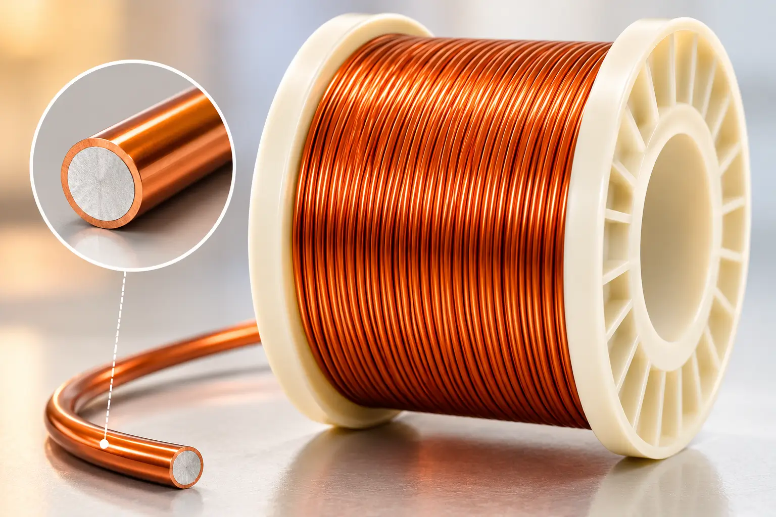
Manufacturing defects are defects that are buried in the production process. These include pinholes in the enamel coating, bubbles, uneven coating, insufficient curing, black oxide spots on the conductor surface, and wire diameter deviations. Initially, these defects are completely invisible, but they quickly become apparent once combined with thermal, electrical, and mechanical stresses.
It is worth noting that the most common latent defect in poor-quality enameled wire is pinhole. Under a microscope, the enamel coating of poor-quality enameled wire is unevenly distributed, with some areas as thin as 50%–70% of the standard value, and even penetrating micropores. This defect is most easily missed during incoming material sampling inspection.
thermal class mislabeled: the slowest yet most ruthless strike.
Incorrect thermal class annotations are the most difficult to detect during the procurement process and have the most serious consequences.
Industry standards require that motors use winding wire with a thermal class of at least Class F (155°C), while high-quality motors generally use Class H (180°C) or higher. However, many low-priced enameled wires on the market are labeled as Class F, but their actual heat resistance is only Class B (130°C) or even lower.
A normally operating motor can reach a winding temperature of 120–140°C. This means that this wire operates under overheating conditions from day one of manufacturing. Under overheating, the enamel coating will gradually soften, blister, and carbonize, causing a simultaneous decrease in both mechanical strength and dielectric strength. When the temperature fluctuates, the enamel layer shrinks slower than the copper conductor, leading to a continuous accumulation of internal stress and accelerating cracking of the enamel coating.
This process, from quantitative to qualitative change, typically takes 6–18 months. This closely matches the actual time it takes for a motor to burn out—which also explains why many failures only occur around one year after the equipment has been in operation.
Why can’t “passing the random inspection” stop it?
Here’s a crucial point to understand: even if a wire passes factory inspection perfectly, its latent defects will gradually amplify and eventually break down under the triple stresses of vibration, temperature cycling, and chemical corrosion during actual motor operation.
This is the root cause of “sudden burnout after 6-12 months of operation.” Inspection can screen out obvious defects, but it cannot screen out latent defects. The real line of defense must be built on control of the entire process, not on a one-time incoming material inspection.
Seven Typical Quality Defects of Poor-Quality Enameled Wire
Identifying defects is the first step in prevention. The following seven categories are the most frequently encountered in actual inspections and failure analyses.
Discontinuity between pinholes and enamel coating. Pinholes are the most common latent defect. The inspection method involves using a high-voltage overvoltage method to detect microscopic insulation defects along the entire wire. The judgment criterion is typically no more than 5 pinholes within 30 meters.
Insufficient or uneven enamel coating thickness. GB/T 6108 and IEC 60317 series specify the insulation thickness for Grade 1/2/3, and the measured deviation should be controlled within ±5%. Insufficient thickness directly equates to zero withstand voltage reserve.
Adhesion and flexibility are not up to standard. The enamel coating and copper conductor are not bonded properly, leading to cracking and peeling during winding, slot insertion, and slot full-rate adjustment. NEMA MW 1000 Table 50 specifically specifies the abrasion resistance test for round wire and magnetic wire; adhesion and flexibility are performed according to NEMA Part 3, Clauses 3.3.1 / 3.3.3 / 3.3.5.
Thermal class} is falsely labeled. This has been discussed in detail earlier. This is the type that most needs to be prevented through document verification and third-party reports.
Conductor Impurities and Oxidation. Black oxide spots and residual chloride ions on the surface of copper wires can induce pitting and micro-corrosion in humid environments.
Dimensional deviations exceeding tolerances. Excessive deviation in wire diameter will reduce space within the slot and affect slot fill rate; excessive deviation will directly increase current density and accelerate temperature rise. Conductor resistance requirements are calculated according to Appendix B of IEC 60317-0-1:2013; nominal resistance is shown in Appendix C.
Insufficient mechanical strength and elongation. Insufficient elongation can lead to wire breakage, deformation, and uneven turn-to-turn tension during winding. Elongation should meet the requirements of standards such as ASTM B1, and is generally not less than 35%.
Prevention Step 1: Design and Material Selection Stage
thermal class should be calculated based on hotspot temperature, not ambient temperature.
The most common selection mistake is using the ambient temperature as the basis for choosing the enameled wire. The temperature rise of the winding itself is between 30 and 80°C, which is much higher than the ambient temperature.
The correct calculation is: Hotspot temperature = ambient temperature + winding temperature rise, and the rated heat resistance must be 20–30°C higher than the hotspot temperature for safety margin. For industrial motors, it is recommended to choose at least Class F (155°C). If the motor operates in high-temperature environments, under frequent heavy loads, or with poor heat dissipation conditions, directly choose Class H (180°C). For high-temperature scenarios, consider EIW/PAIW composite coatings with a 200°C/220°C rating.
According to the IEC 60317 standard, the temperature at any point of the winding should not exceed the limit for the corresponding insulation class.
| Insulation class | Temperature limits (°C) | Temperature limits (°F) |
|---|---|---|
| E | 120 | 248 |
| B | 130 | 266 |
| F | 155 | 311 |
| H | 180 | 356 |
| C | 200 | 392 |
| C+ | 220 | 428 |
The enamel coating type must correspond to the winding process.
In scenarios with high automatic winding, insertion, and slot fullness, adhesion requirements are more stringent. High-adhesion enameled wire is a reasonable choice for this type of application.
220-grade AIW (polyamide-imide single-coat) is another option for high-temperature applications—its entire insulation layer is composed of pure polyamide-imide resin, with a long-term operating temperature of 220°C. While official ratings are mostly 220°C, its softening breakdown temperature is typically greater than 330–350°C. It exhibits extremely low internal stress under thermal shock exceeding 200°C, preventing cracking. Its mechanical abrasion resistance also far surpasses that of ordinary polyester (PEW) and polyester imide (EIW).
Variable frequency drive motors require separate consideration. The high-frequency voltage pulses and overshoots of PWM inverters can create extremely strong electric field stress at the winding initiation point, easily inducing partial discharge. For these applications, an enamel coating system with corona-resistant properties should be selected, or the insulation level at the initiation point should be improved during the manufacturing process.
When selecting a model, the standard correspondence should be confirmed.
Don’t just look at the phrase “complies with IEC 60317”. The specific models and standard clause number are the true indicators of traceability. For example, consider polyurethane enameled wire:
| Thermal class | Insulation type | NEMA MW 1000 | IEC 60317 |
|---|---|---|---|
| 155°C | Polyurethane-155 | MW 79 | 60317-20 |
| 155°C | Polyurethane-Nylon-155 | MW 80 | 60317-21 |
| 155°C | Polyurethane (bondable)-155 | MW 131 | 60317-35 |
| 155°C | Polyester glass fiber-155 | MW 45 / MW 46 | 60317-60 |
| 180°C | Polyurethane-180 | MW 82 | 60317-51 |
| 180°C | Polyurethane-Nylon-180 | MW 83 | — |
Copper versus aluminum conductor should also be clearly specified based on cost and weight requirements. Copper-clad aluminum (ECCAW) can significantly reduce material costs for the same weight, but it is necessary to confirm with the supplier the interfacial metallurgical quality, the adhesion performance of the insulating enamel coating to the substrate, and the actual rated value of the thermal class.
Prevention Step Two: Incoming Inspection Stage
IQC Mandatory Inspection Items List
Incoming inspection is not simply “testing one roll”. The table below shows the recommended minimum set of mandatory inspections:
| Inspection items | Test methods | Judgment basis | Test frequency |
|---|---|---|---|
| Appearance and integrity of the enamel coating | Visual inspection / 10x magnifying glass | No cracks, bubbles, peeling, or pinholes. | 100% visual per batch |
| Conductor diameter and enamel coating thickness | micrometer / laser thickness gauge | Deviation ≤ ±5% | Sampled per batch. |
| DC resistance (DCR) | micro-ohmmeter | Compliant with IEC 60317-0-1 Annex B / C | Every reel |
| Breakdown voltage | breakdown voltage tester | Not lower than the specified value | Sampled per batch. |
| Pinhole detection | High voltage path overvoltage method | ≤ 5 pinholes within 30 m | Sampled per batch. |
| elongation | Electronic tensile testing machine | ≥ 35% (as per standard requirements) | Sampled per batch. |
| abrasion resistance | Steel needle scribing / NEMA MW 1000 Table 50 | insulation resistance maintained at ≥ 100 MΩ | Sampled per batch. |
| adhesion and flexibility | Quick pull around the axis / Needle wrap | Enamel coating free of cracks and peeling | Sampled per batch. |
| thermal shock | Winding at 175–220°C for 30 min | No cracks, no peeling | Sampled per batch. |
| Chemical resistance | Soak in acetone/xylene at 23°C for 1 hour. | No swelling, no peeling | Sampled per batch. |
A feasible and rapid field testing method
This is the simplest verification method, requiring almost no equipment: Take a 1-meter-long enameled wire sample, wrap it 10 times around a needle of the same diameter as the enameled wire, remove it, and immediately place it in a 130°C oven for 30 minutes. After cooling, visually inspect the enameled coating for any visible cracks, bubbles, or peeling.
Simultaneously, the insulation resistance should be measured using a 500V megohmmeter and should remain above 10^11 Ω. If any of these tests fail, the entire lot is deemed “adhesion failure”.
Sampling plans should be based on risk levels.
For key applications—new energy vehicles, drive motors, high-end home appliance production lines, and military applications—it is recommended to adopt AQL 0.065–0.10 of GB/T 2828.1 / ISO 2859-1, with general inspection level II, and 5–10 pieces per batch. For ordinary industrial motors, the requirements can be relaxed, but it is recommended that the three core parameters (wire diameter, DCR, and breakdown voltage) be tested for every roll, and samples should be retained to support traceability.
Procurement specifications must be quantified.
This is the most easily overlooked but most beneficial step: Write acceptance criteria into the procurement specifications, instead of simply stating “compliant with IEC 60317”.
A qualified high-bonding enameled wire procurement specification should clearly state: compliance with IEC 60317-13 (Class 180 EIW) or higher standards; nominal conductor diameter range; enameled coating thickness grade (Grade 2); no visible cracks in the enameled coating after winding with a needle of the same diameter; no cracking or peeling of the enameled coating after being kept at 200°C for 72 hours; a breakdown voltage not less than 100% of the specified minimum (factory condition); and a factory inspection report and material certificate provided for each lot.
The cost comparison brought about by quantified clauses is very intuitive: Each instance of early failure caused by enamel coating peeling results in a magnified cost in the after-sales process that is dozens of times the material cost. Simply writing the requirements into the procurement specifications merely shifts this cost upstream in advance.
supplier audit and retrospection
During the factory audit, four key things are examined: the stability of the temperature curves of the paint and the oven and the traceability of the paint; the completeness of the enamel coating and pinhole testing equipment and the pressure resistance testing equipment; whether there is a laboratory capable of performing tan δ loss angle tests, high and low temperature thermal shock tests and accelerated aging tests; and packaging protection (vacuum sealing, desiccant, edge protection, and anti-oxidation).
Suppliers are required to provide a Certificate of Analysis (CoA) for each lot, and the return and replacement terms and liability boundaries for non-conforming products must be specified in the supply agreement.
Prevention Step 3: Winding and Assembly Process
winding tension and slot internal arrangement
Once the conductor cross-section and thermal class are confirmed, the winding tension becomes the key variable for protecting the enamel coating. Insufficient tension results in loose winding and uneven turn-to-turn compression, making the coating prone to wear during vibration. Excessive tension can directly crack the enamel coating during the slot insertion stage. The motor end is the location where vibration is most concentrated and where the enamel coating is most susceptible to cracking.
High-speed automatic winding is the primary scenario for mechanical damage to the enamel coating—continuous friction between the wires and the guide rollers and tension rollers will continuously thin the enamel coating. Special attention should be paid to the material and surface condition of the guide rollers in this section.
slot insulation and phase-to-phase insulation
The enamel coating on the enameled wire itself is only the first line of defense. Slot insulation provides mechanical protection, while phase-to-phase insulation provides electrical isolation. The absence or misalignment of these two layers will cause the enamel coating to bear stress beyond design expectations.
When designing, check the voltage level and overvoltage multiple, not the rated voltage.
turn-to-turn Insulation and end support
For variable frequency drive motors and high-reliability applications, turn-to-turn insulation is an additional cost investment, but it significantly improves partial discharge immunity. End supports must ensure that the winding does not shift under electromagnetic forces—the first point of contact for turn-to-turn short circuits is often at the end.
impregnation and VPI processes
Vacuum pressure impregnation (VPI) can fill the micropores of the enamel coating, lock the winding, and eliminate air bubbles, significantly improving the continuity and moisture resistance of the heat dissipation path. Process parameters need to be controlled: pre-baking temperature and time, vacuum level, impregnation pressure, and curing curve. The impregnation coating itself must have good compatibility with the enamel coating—incompatibility will cause swelling or peeling of the enamel coating, which is a typical chemical failure.
Prevention Step 4: Finished-Motor Validation Stage
Electrical tests required before shipment
Withstand Voltage Test: 1.5 times the rated voltage + 1000 V, for 1 minute, with no breakdown or flashover.
Insulation resistance: 500 V or 1000 V megohmmeter. A resistance below 1 MΩ indicates insulation degradation, and below 0.1 MΩ indicates a hard ground fault. New motors generally require a resistance of 100 MΩ or higher.
Three-phase DC resistance balance: An imbalance exceeding 4% indicates localized wind damage; it should be within 2%.
No-load test: Record the no-load current and no-load loss. The three-phase current imbalance should be less than 10%. Simultaneously monitor the winding and temperature rise.
Temperature rise test: This test verifies the operation within the insulation class limits. Typically, a 2-hour stable temperature rise test is performed to confirm that there is sufficient margin for hot spot temperature.
accelerated aging verification
If the project has high reliability requirements, performing accelerated thermal aging is worthwhile. Following the Arrhenius model, run the system at temperatures above the rated value to verify the performance retention of the enamel coating and check the accuracy of the thermal class calibration. This step is specifically designed to detect “dummy thermal class calibrations”—dummy calibration lines will quickly become apparent under accelerated conditions.
Overall protection configuration
The motor’s own protection configuration is the last line of defense. Thermal relays are set at 1.05–1.1 times the rated current; phase loss/phase failure protection and stall protection are provided; for frequency converter applications, dv/dt filters or sine wave filters are used to reduce impact; thermistors or PTCs are used for direct temperature monitoring.
Prevention Phase 5: Operation and Maintenance Phase
Regular insulation resistance measurement
This is the simplest and most effective operational monitoring method. It is recommended to measure quarterly using a 500 V megohmmeter; the reading should remain above 100 MΩ. The trend is more important than a single value—if the reading drops from 500 MΩ to 80 MΩ within two quarters, even if it hasn’t reached the alarm threshold, a preventative check should be scheduled.
Inspection points
Pay attention to the temperature rise trend, any abnormal noise or vibration, any burning smell, and any discoloration at the tip of the wind. Infrared thermal imaging can detect hotspots in advance while in operation; it is inexpensive but highly valuable.
heat dissipation and cleaning
Blocked air ducts, fan malfunctions, and excessively high ambient temperatures can all reduce heat dissipation capacity. Accumulated dust can form an insulating layer, effectively turning the motor into a “boiler in its own hot exhaust.” Regularly cleaning heat dissipation channels is one of the most cost-effective preventative measures.
Motor current characteristic analysis
For critical equipment, Motor Current Characteristic Analysis (MCSA) can identify stator and rotor faults through current spectrum analysis without disassembling the machine. Operating data can also reflect three-phase imbalance.
Field identification of phase loss and overload
Traces of a burned-out motor can be analyzed to trace the failure path.
| Failure Mode | Typical trace characteristics |
|---|---|
| Overload | The three-phase winding turns black and brittle with overall aging; the enamel coating discolors uniformly; and in severe cases, it carbonizes into powder. |
| Phase loss | One phase is severely carbonized, while the other two phases are slightly carbonized, and there is a noticeable humming sound during operation. |
| turn-to-turn short circuit | Localized hotspots, relatively clean interior of the cavity, single obvious breakdown point. |
| Phase-to-phase/grounding | The breakdown area is quite large, with obvious burn marks. |
This set of trace characteristics is an important basis for determining the root cause in 8D analysis, and it is also the key to distinguishing between “enameled wire quality problems” and “improper use/protection”.
Boundaries of Responsibility for enameled wire Failure
Finally, let’s discuss an issue that both the purchasing and manufacturing parties need to clarify.
The attribution of responsibility for motor burnout caused by the failure of the enameled wire must be determined by the chain of evidence, not by speculation.
- If the incoming inspection record shows that all indicators are qualified, but the failure analysis proves that the latent defects were amplified under multiple stresses, then the responsibility lies with the enameled wire supplier—which is why it is meaningful to require batch sampling and lot traceability.
- If evidence shows that the motor winding process parameters (tension, slot, slot insulation, impregnation) deviated from the requirements, then the responsibility lies with the motor manufacturing end;
- If the protection configuration or operating conditions are abnormal (long-term overload, operation with a phase loss, heat dissipation failure, voltage deviation exceeding ±10%), then the motor itself is of good design and the problem lies with the user.
If any link in this chain is missing, the responsibility for the failure cannot be determined. The sample retention system, process records, and whole-machine test reports constitute a complete chain of evidence.
Summary: Five-Step Prevention Framework
Returning to the initial question—why do motors that have passed inspection still burn out? Because inspection can only filter out visible defects, not latent defects, and it cannot replace process control.
To prevent motor burnout caused by poor-quality enameled wire, five crucial steps must be taken:
Design and Material Selection — Select thermal class based on the hot spot temperature plus a 20–30°C margin, select enamel coating type based on the winding process, and lock models according to the standard bar number instead of just writing “compliant with IEC”.
Incoming Inspection — Establish an IQC mandatory inspection checklist, with the three core items required for every roll, and key applications sampled at AQL 0.065–0.10. Quantify the acceptance criteria and write them into the procurement specifications.
Winding process—Control tension and turn-to-turn stress, configure slot insulation and phase-to-phase insulation, add turn-to-turn insulation and end supports as needed, and process parameters.
Finished-Motor Validation—Tests include withstand voltage, megohms, three-phase resistance balance, no-load temperature rise, and thermal aging. Factory protection configurations are in place.
Operation and Maintenance — Quarterly insulation resistance measurement and trend tracking, infrared thermal imaging to identify hot spots, regular cleaning of heat dissipation channels, and current characteristic analysis of operational data.
In our experience, problems often don’t stem from a single missed step, but rather from a lack of closed-loop coordination between steps. We assume everything is fine once the incoming materials pass inspection, only to discover during failure analysis that the winding tension has already exceeded the acceptable range; we consider a machine reliable once it passes overall testing, only to revert to checking for a single pinhole on a wire when the equipment burns out at the customer’s site.
By linking the five links into a traceable chain, poor-quality lines cannot be used in the motor.