

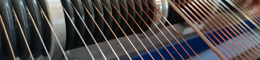
In winding design, different wire segments within the same coil or motor stator often carry completely different temperature loads. The turns at the bottom of the slot sit against the core and dissipate best; the turns at the slot opening sit in the airflow and take mechanical scraping during insertion; the lead wire may even run to terminals in a 180°C cabinet. Using one thermal class for the whole device then becomes a dilemma — a lower grade is cheap but will not survive the hot sections, while a higher grade everywhere wastes money.
The practice of “mixed winding” emerged from this: different temperature grade enameled wire placed where the material is actually needed. The idea is sound, and standard practice in motor design. Yet mixed windings fail regularly in the field, and the cause is rarely “the wrong thermal class was chosen.” It is that four things were never calculated: how the lowest thermal class sets the limit, how thermal expansion differences are handled, whether the enamel coatings react with each other, and whether the coating thicknesses still fit the slot. This note works through those four points.
Basic Concepts and Applicable Scenarios of Mixed Winding
What Is Actually Mixed in a Mixed Winding?
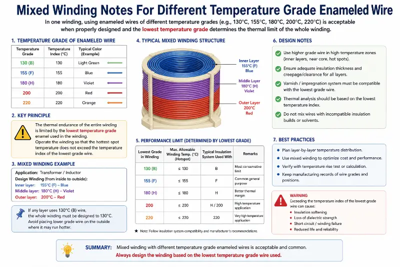
Strictly, a mixed winding uses two or more conductors or enameled wires of different temperature grade in the same winding. Three forms show up in practice:
Mixing thermal classes — 155-grade polyester enameled wire in the slot, 200-grade polyester-imide/polyamide-imide composite for the crimped or high-temperature lead section.
Mixing conductor materials — copper in the main body to keep resistance low, copper clad aluminum (CCA) or aluminum on long spans where copper is not critical.
Mixing enamel grades — Grade 1 (single layer) and Grade 2 (double layer) within one thermal class, with Grade 2 at the winding ends where mechanical stress is highest.
All three are common in motor plants, but mixing temperature grade enameled wire causes the most trouble, because it couples thermal aging, stress distribution, and insulation coordination.
Which Scenarios Really Require Mixed Winding?
High-temperature leads and external connections are the clearest case. The stator coil of enameled wire runs fine at Class 155, but the terminals sit in a control cabinet where 150°C is normal, so that section needs Class 200 or 220 wire. It is usually only 5% to 10% of total length, and the cost increment is a small fraction of the machine — a very favorable trade.
The slot transition section comes next. Automatic insertion machines do the most severe coating abrasion at the slot opening, where flattened wire and scratched-through coating are far more common than at the slot bottom. A common practice is Grade 2 heavy-grade wire through the slot, with only the two or three most exposed turns at the opening in a higher-grade composite.
Automotive and new-energy drive motors are the most refined case. The hairpin winding has three stress concentrations — solder joints, corners, and hairpin roots — whose temperature distribution differs completely from plain round wire. Typical specifications call for 180-grade EIW on the straight sections and 200-grade EI/AIW on the corner reinforcement.
In transformers and inductors, the mixing is mostly of conductor materials rather than thermal classes. Internal temperature differences are small, so thermal class mixing is uncommon; but matching insulation thermal classes across oil-immersed and dry-type assemblies becomes a different kind of mixing problem.
Where Is Mixed Winding Unsuitable?
Three cases are better served by a single class across the whole winding:
Windings that need complete rewinding or frequent repair. Different temperature grades age at different rates. Ten years in, a 180-grade section may still be sound while a 200-grade section has embrittled, and the slot fit dimensions change once the coil is replaced.
Molded windings with strict inter-turn insulation coordination. In large motor formed coils, different classes on the same turn force the inter-turn pad to carry the highest thermal class, or the pad compressed at the hot section deforms.
High-reliability, safety-critical applications — traction transformer windings, nuclear auxiliary motors, elevator traction braking windings. The material saved is negligible next to the cost of an early failure.
The Shortcoming Principle for Thermal Class Selection
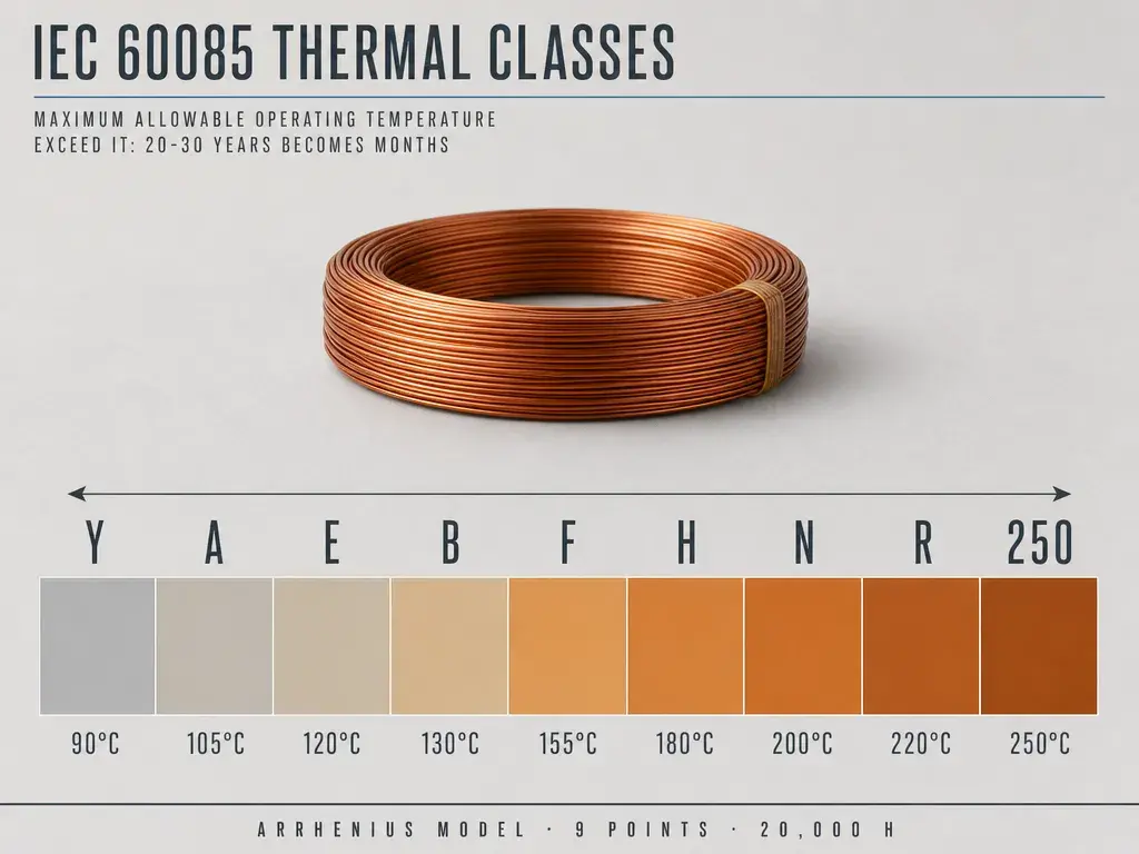
Insulation Class System and Temperature Correspondence
According to the IEC system, the insulation class indicates the highest operating temperature that no part of the winding should exceed. This is a basic table for mixing insulation:
| Insulation Class | Thermal Class | °C | °F | Typical Enamel Coating System |
|---|---|---|---|---|
| E | Class E | 120 | 248 | Polyvinyl Formal (PVA) |
| B | Class B | 130 | 266 | Polyurethane (UEW), Modified Polyester |
| F | Class F | 155 | 311 | Polyester (PEW) |
| H | Class H | 180 | 356 | Polyester Imide (EIW) |
| C | Class 200 (N) | 200 | 392 | Polyester Imide/Polyamide-Imide Composite (EI/AIW) |
| C+ | Class 220 (R) | 220 | 428 | Polyamide-Imide (AIW) |
| — | 240 grade | 240 | 472 | Polyimide (PIW) |
One point is easily confused: letter grades (E/B/F/H/C) and numerical grades (130/155/180/200/220/240) are two parallel labeling conventions. The former is the IEC 60317 insulation class letter, the latter the temperature index used by NEMA and many Asian standards. The same wire is labeled differently under different systems, but the physical meaning is the same. NEMA MW 1000-2018 splits enameled wire into part numbers by thermal class, coating type, and enamel grade (Grade 1/2/3). IEC 60317 splits by product type: IEC 60317-3 (155 grade polyester), IEC 60317-8 (180 grade polyester-imide), IEC 60317-13 (200 grade composite), IEC 60317-46 (240 grade polyimide).
Why the Lowest Grade Sets the Limit
Once the temperature exceeds what the lowest-grade wire can take, that segment sets the lifespan of the whole winding. This is not conservatism; it is physics. Take a winding mixing 180 and 200 grade wire with a local hotspot of 195°C. For the 200 grade wire, 195°C is below its 200°C temperature index and the thermal stress is acceptable. For the 180 grade wire, it is 15°C over. By the Arrhenius thermal aging model and the engineering “10°C rule” — every 10°C rise roughly doubles the chemical aging rate of insulation — a Class 180 wire at 195°C retains only about one-third to one-quarter of its nominal thermal life. A winding designed for 20,000 hours may crack its coating in six or seven years.
Worse, local overheating gets averaged out. Many motors carry thermistors or thermocouples reading winding average or core surface temperature, which masks hot spots. The machine looks safe at 160°C while one section is continuously baking at 195°C. This masking happens far more often in mixed windings, because different classes naturally age at different rates.
The design principle of mixed winding is therefore: set the machine’s life and temperature-rise limit by the thermal capacity of the lowest temperature grade segment. Higher-grade sections add value only by not becoming the weak link and by covering extreme conditions. They do not extend the machine’s life.
Relationship Between Thermal Shock Temperature and Temperature Index
Beyond continuous operating temperature, enameled wire of any temperature grade carries a “thermal shock temperature” index. For 200 grade wire, the temperature index requirement is 200 and the thermal shock requirement is at least 220°C. That 20°C gap is not arbitrary. Enamel coatings are thermosetting polymers with uneven cross-link density. During a rapid temperature rise — motor startup, or cooling after an overload trip — the outer surface of the coating expands faster than the inner layer, generating internal stress. The thermal shock index measures the coating’s ability to survive such short, fast temperature changes without cracking or losing adhesion.
In a mixed winding, if the thermal shock capability of the two classes differs sharply and the sections are adjacent, as at a slot transition, the expansion difference during fast cycling builds interfacial stress. The typical failure is that the high-grade coating itself stays intact while radial cracks open at the coating edge of the transition point.
Difference in Thermal Expansion Coefficients and Mechanical Fit
Thermal Expansion Differences Between Enamel Coating and Copper
The thermal expansion coefficient of pure copper is approximately 17 × 10⁻⁶/K. At a temperature rise of 180°C relative to 25°C (ΔT = 155 K), the free elongation of the copper conductor is approximately 0.26%. The coefficients of thermal expansion vary greatly among different enamel coatings:
| Material | Coefficient of Thermal Expansion (×10⁻⁶/K) | Notes |
|---|---|---|
| Copper Conductor | ~17 | Reference |
| Polyurethane (UEW) | 100–130 | Elastomer, low modulus |
| Polyester (PEW) | 60–90 | |
| Polyester Imide (EIW) | 40–60 | |
| Polyamide-Imide (AIW) | 30–50 | High crosslinking density, significant shrinkage |
| Polyimide (PIW) | 30–45 |
The table shows it plainly: AIW-type coatings expand about 2 to 3 times more than copper, and UEW-type up to 7 times. Heated from 25°C to 180°C, the copper conductor elongates 0.26% while the AIW coating would want more than 0.5%. The coating is wrapped around the copper and cannot expand freely, so the entire difference becomes residual stress inside the coating, and AIW takes compressive stress on cooling. Copper’s elastic modulus is two orders of magnitude higher than the coating’s, so the coating absorbs nearly all the deformation. Copper-core enameled wire manufacture therefore includes a tempering step to release this residual stress. Composite EI/AIW wire is worse, because the base and surface layers shrink at different rates, so post-processing must be controlled more tightly.
Specific Manifestations in Mixed Winding
When two temperature grade enameled wires sit adjacent in one slot or meet at a winding end, the shrinkage difference acts directly on the coating-copper and coating-coating interfaces. Two manifestations recur:
Peeling at the transition point. Connections are crimped or welded, and thermosetting coatings carbonize locally under weld heat. The different carbonization residues leave microscopic voids that grow into interface delamination under vibration and thermal cycling.
Abnormal slot friction during insertion. Surface friction coefficients differ. 200-grade composite wire has a low-friction AIW surface, while 155-grade PEW is grippier. Mixed in one slot, the unequal drag at the slot opening causes uneven lay-up and turn-to-turn compression.
Remedy: insert a short transition wire, typically 50 to 150 mm, of an intermediate grade (180 grade when stepping from 155 to 200). Its length should be calculated from the actual temperature gradient, not guessed.
Matching with Slot Insulation and Slot Wedges
Mixing also affects mechanical fit. Grade 2 enameled wire of the same nominal diameter has an outer diameter 15% to 20% larger than Grade 1. With a single grade this is trivial — just calculate slot fill factor on Grade 2. Mixing Grade 1 and Grade 2 puts two outer diameters in the same slot layer, so the cross-section is no longer a neat rectangle and fill factor must be checked at worst case. One typical failure: a customer swapped the bottom two turns from Grade 2 to Grade 1 to save money, judging the short-circuit risk low. Slot fill factor rose from 78% to 86%, the insertion pusher would not press down, and the job moved to hand insertion. Labor cost far exceeded the material saving.
Enamel Coating System Compatibility and Breakdown Voltage Compatibility
Whether Different Enamel Coating Systems Can Contact Each Other Directly
Polyester types (PEW / modified polyester) with polyurethane (UEW): generally compatible. Both belong to the relatively mild polyester family and usually show no significant chemical reaction.
Polyester-imide (EIW) with polyester-imide/polyamide-imide composite (EI/AIW): compatible. EI/AIW is built on an EIW base layer.
Polyamide-imide (AIW) with polyimide (PIW): generally compatible. AIW is essentially a prepolymerized polyimide system.
Polyester/polyurethane (PEW/UEW) with polyimide (PIW): requires attention. PIW’s pyrolysis temperature and residue differ sharply from polyester, forming a different kind of residue layer in the end-welding area.
Halogenated or sulfur-containing flame-retardant coatings with ordinary coatings: the critical one. Refrigerant-resistant and flame-retardant grades carry special additives, and contact-surface compatibility with ordinary coatings must be confirmed by the coating supplier.
Aluminum crimped directly to copper: not a coating issue, but equally critical. The aluminum oxide film destabilizes contact resistance. Aluminum-copper transitions in mixed-conductor windings require bimetallic transition terminals; direct stranding is unacceptable.
Coating contact surfaces and stripping: at mixed-wire transition ends the stripping length must be controlled tightly. UEW can be mechanically or thermally stripped; AIW and PIW normally need heat plus mechanical scraping. Because AIW is highly cross-linked, forcing mechanical stripping roughens or even breaks the copper strands, leaving stress concentrations on the crimped face.
Breakdown Voltage Compatibility Requirements
The minimum breakdown voltage requirement varies depending on the enamel grade. Taking IEC 60317-0-8 (polyester) glass fiber wrapped enameled flat copper wire as an example, the standard requirements for breakdown voltage are as follows:
| Insulation Type | Minimum Breakdown Voltage (RMS) V |
|---|---|
| Bare Conductor | — |
| Single-layer coating (PG1) | 350 |
| Double-layer coating (PG2) | 560 |
| Class 1 (enameled wire) | — |
| Single-layer coating (Class 1 PG1) | 1350 |
| Double-layer coating (Class 1 PG1) | 1560 |
| Class 2 (enameled wire) | — |
| Single-layer coating (Class 2 PG1) | 2350 |
| Double-layer coating (Class 2 PG2) | 2560 |
This data reveals an important fact: the breakdown voltage gain from moving from Grade 1 to Grade 2 far exceeds the gain from moving up in thermal class. The step from 1350 V to 2350 V is +74%, while going from 155 to 200 grade raises the requirement only from roughly 3300 V to the 5000 V range, about +50%.
The comparison settles a commonly confused point. If the goal is inter-turn reliability, moving to Grade 2 is more direct and effective than moving up in thermal class, because inter-turn voltage is set by turn count, not by the class. Thermal class addresses heat; grade addresses electric stress.
In a mixed winding of different temperature grade enameled wire containing both Grade 1 and Grade 2, the inter-turn withstand test must be judged on the Grade 1 portion. It cannot be judged as Grade 2 just because most of the slot is Grade 2.
Additional Requirements for Class 200 Wire
Class 200 composite enameled wire carries three further requirements that are easily missed in mixed work:
- Extractable substances not exceeding 0.5%. This targets residual solvents and low-molecular-weight material in the coating. In enclosed or hot environments — local hot spots from inverter harmonic losses, or a varnish impregnation tank — volatilized residues cause bubbling and viscosity shifts.
- Breakdown voltage of 75% of the specified minimum. This is the lower judgment limit for sampled product, so batch consistency must be held well above “just passing.”
- Thermal shock temperature of at least 220°C.
Engineering Criteria and Design Process for Mixed Winding
Four Feasibility Criteria
Mixed winding with different temperature grade enameled wire is only defensible when all four of these hold. If one fails, do not mix.
Criterion 1 — Thermal class matching. Every segment of temperature grade enameled wire must survive the highest local temperature in the winding, and that limit comes from the lowest segment, not the highest. Use the measured or simulated hotspot temperature, never the average temperature rise.
Criterion 2 — Comparable thermal expansion coefficients. Differences between adjacent segments of different classes create interfacial stress. The larger the difference, the more necessary a transition segment, with length calculated from the temperature rise gradient.
Criterion 3 — Coating chemical compatibility. The two coatings must not react at the contact surface in a way that degrades the interface, and stripping processes must be compatible — either both strip thermally, or both use the same mechanical method.
Criterion 4 — Consistent coating thickness and mechanical fit. Mixing Grade 1 and Grade 2 changes slot fill factor, so fill factor and slot insulation mechanical strength must be rechecked at worst case.
Five-Step Selection Process
Step 1 — Establish the highest operating temperature of each segment. List temperatures segment by segment, not one temperature for the machine. The terminal area, in-slot straight sections, slot opening transitions, and winding ends each need a basis: measured temperature rise, finite element simulation, or comparable product data plus margin.
Step 2 — Set the baseline thermal class from the lowest segment. The benefit of mixing only comes from covering the hot segment; the baseline is set by the coolest one.
Step 3 — Choose the upgrade for the hot segment. Options are changing thermal class (155 PEW to 180 EIW), increasing coating thickness (Grade 1 to Grade 2), or adding transition segments. Prefer changing thermal class, because a grade upgrade brings slot fill factor problems with it.
Step 4 — Verify transition points and end terminations. Stripping method, crimping method, welding temperature profile, and transition length each need separate confirmation.
Step 5 — Run thermal aging verification on the mixed winding. This is the critical step most often skipped. Put proportionally mixed assembled samples — not single-grade samples — into an aging chamber at the highest operating temperature plus 10 to 20°C, run accelerated aging, then measure breakdown voltage and elongation. A single-grade sample passing proves nothing about the mixed assembly.
Common Failure Modes of Mixed Winding
Six failure modes account for most field cases:
Local thermal stress cracking. Expansion mismatch across the transition opens radial cracks at the coating edge after repeated cycling, appearing as a localized inter-turn short.
Contact resistance drift at the transition point. The crimp or weld interface oxidizes under cycling, and resistance drifts from milliohms to ohms. Temperature rise rises with it, and the result feeds back on itself.
Coating delamination and creepage. Different coatings leave different stripping residues, and carbides at the interface form conductive paths that creep in humid or condensing environments.
Inter-turn stress concentration leading to early open circuits. High-grade coatings have high modulus and poor elasticity. Insertion stress at the slot opening creates micro-cracks inside the coating. Insulation resistance reads normal, then the turn opens after a few thousand hours.
Thermal monitoring error. The thermocouple may not sit on the lowest-grade segment, so readings look normal while the section is over temperature.
Maintenance traceability failure. Years later a local repair is needed, but the different classes are not consistently marked in stores, and mixed installation breaks the batch traceability chain.
Recommendations for Mixed Winding Selection
Mixed winding with different temperature grade enameled wire pays off where the temperature spread is large but the hot segments are short. The high-temperature lead is the typical case: 5% to 10% of total length, but it carries most of the temperature-rise margin. Upgrading that 10% to a higher class typically adds 2% to 5% to cost and widens the thermal design margin across the machine. That is a good trade.
The reverse also holds. If the temperature distribution is already uniform and segment temperatures differ by less than 20°C, do not mix temperature grade enameled wire. Mixing adds procurement, inventory, inspection, and process complexity, introduces another failure mode, and the return does not cover it. For such projects the sound recommendation is a single grade across the whole winding.
For coating system upgrades, follow the IEC 60317 ladder. The easiest step is 155 grade polyester (IEC 60317-3 / NEMA MW 5-C) to 180 grade polyester-imide (IEC 60317-8 / MW 30-C): the conductor stays the same, only the coating system changes, and the processing equipment and inspection routines barely move. Going to 200 grade composite (IEC 60317-13 / MW 35-C, MW 73-C) also requires the base-to-surface layer ratio — standard practice is 70% to 80% EIW base with 20% to 30% AIW surface. That split balances heat resistance, lubricity, and cost.
Solderability deserves separate attention. 155 and 180 grade polyurethane (UEW) can be soldered through the coating with no mechanical stripping, and that is often the only reason it was chosen. If the design needs solderable 155 UEW somewhere while the mixed logic demands 180 grade elsewhere, that section must be stripped before soldering, and process cost and reliability risk both need recalculating. This is typically discovered late in design, when changes are expensive.
Finally, any mixed winding design of temperature grade enameled wire should be verified on mixed samples before it reaches production. A single-grade report says nothing about long-term reliability at the mixed interface, which is precisely the weakest point in the design. Set test conditions at the highest local operating temperature plus 10 to 20°C, configure the sample mix by the actual segment length proportions, and measure breakdown voltage, elongation, and coating adhesion afterward. The cost is negligible against a motor that fails on site after five years.
Zhengzhou Zhonglin Industrial Co., Ltd. supplies enameled wire across the full 155/180/200/220/240 thermal class range, with copper, aluminum, and CCA conductors, covering round wire from 0.016 to 7.0 mm and flat wire from 0.8 to 10 mm thick and 2 to 25 mm wide, to IEC, GB, JIS, and NEMA standards. The plant operates ISO 9001, ISO 14001, and ISO 45001 systems with UL, REACH, and RoHS compliant products, and with 30 years in magnet wire export it supports the split-batch delivery and batch traceability a mixed winding project needs. Contact: office@cnlpzz.com, WhatsApp 0086-19337889070.
Summary
Mixed winding is temperature grading management — putting each temperature grade enameled wire where it is actually needed. It holds together only when four things hold at once: the lowest thermal class sets the baseline, transition sections control the thermal expansion difference, the coating systems are chemically compatible, and coating thickness and slot fill factor are verified at worst case.
In practice three actions are enough. List the highest operating temperature of each segment instead of assigning one temperature to the whole machine. Prefer upgrading the thermal class over blindly moving to Grade 2, since a grade change hits slot fill factor directly. And before production, run accelerated aging on a sample mixed in the real proportions — a single-grade report cannot prove the mixed interface.
As for whether to mix at all, do the arithmetic. Where temperature distribution is uniform and segment differences are within 20°C, the return does not cover the complexity. Where a high-temperature lead runs 5% to 10% of the length but carries the largest margin, that is where mixed winding earns its keep.