

Copper enameled wire motor coils may experience typical damage during long-term operation, such as conductor scratches, enamel film breakdown, lead wire breakage, and inter-turn short circuits. For on-site maintenance technicians, determining the boundary between “whether partial repair is possible” and “whether full rewinding is necessary” is often more challenging than the repair action itself. This article uses damage quantification and grading as its framework, combined with the standard anchors of IEC 60317 and NEMA MW 1000-2018, to systematically outline the complete decision-making path from fault diagnosis and temporary treatment to permanent rewinding.
Damage Classification: Quantify First, Then Act
Before any repair work can be done, one question must be answered: How much of the conductor’s cross-sectional area has been lost? This number will determine the direction of all subsequent solutions.
Quantitative Boundaries of the Three Damage Classes
In engineering practice, the most commonly used classification criterion is the conductor cross-sectional area loss rate, which directly reflects the margin between current carrying capacity and mechanical strength.
| Damage type | Cross-sectional area loss | Typical manifestations | Main risks |
|---|---|---|---|
| Surface scratches | <10% | The paint film is damaged, and the copper surface is visible but not broken. | Localized electric field concentration accelerates insulation aging. |
| Partial fracture | 10%–30% | Some copper wires are broken or loose | Uneven current distribution causes the remaining copper wire to overheat due to overload. |
| Severe fracture or transection | >30% | The copper wire is completely broken or missing over a large area. | Insufficient current carrying capacity may lead to arc discharge. |
The danger of scratches lies not in their immediate failure, but in the creation of a “concentration point of electric field.” Under an alternating current electric field, sharp defects on the conductor surface can significantly amplify the local electric field strength, triggering partial discharge of the enamel film. This damage often evolves into an inter-turn short circuit months later, a typical example of a latent failure.
Partial breakage is considered a manifest failure. With fewer copper strands, the remaining copper wires are forced to bear the entire current density, causing a rise in temperature. Under rated load, a previously qualified winding may directly trigger an over-temperature alarm.
Diagnostic Workflow: From Symptom to Location
On-site diagnosis should follow the order of “external before internal, electrical before mechanical” to avoid blind disassembly.
- Power Outage Confirmation — Disconnect the power supply and tag the affected area. Measure the resistance of the three-phase windings. Any abnormal resistance or open circuit in any phase indicates damage to the winding itself.
- Visual Inspection — After removing the end cap, look for signs of discoloration. Burnt insulation usually presents as localized dark brown areas accompanied by a carbonized odor.
- Megohmmeter Screening — A 500V megohmmeter measures the insulation resistance to ground; a reading below 5MΩ indicates insulation failure, requiring further investigation.
- DC Resistance Comparison — A three-phase resistance imbalance exceeding 4% indicates a broken strand or short circuit in the winding.
It is important to emphasize that discoloration marks are often not located at the actual fault point. The current generates an arc at the break, and carbides diffuse along the magnetic field direction, easily causing misinterpretation. The true break point is usually located at points of stress concentration during bending, such as the slot outlet, the root of the lead wire, or the transition section of a jumper wire.
Enamel Damage: Film Broken, Conductor Intact
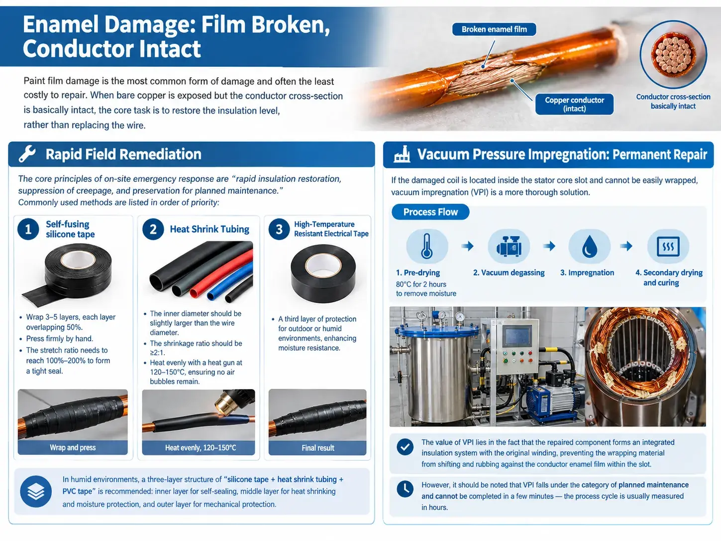
Paint film damage is the most common form of damage and often the least costly to repair. When bare copper is exposed but the conductor cross-section is basically intact, the core task is to restore the insulation level, rather than replacing the wire.
Rapid Field Remediation
The core principles of on-site emergency response are “rapid insulation restoration, suppression of creepage, and preservation for planned maintenance.” Commonly used methods are listed in order of priority:
- Self-fusing silicone tape — Wrap 3–5 layers, each layer overlapping 50%, and press firmly by hand; the stretch ratio needs to reach 100%–200% to form a tight seal.
- Heat Shrink Tubing — The inner diameter should be slightly larger than the wire diameter, and the shrinkage ratio should be ≥2:1. Heat evenly with a heat gun at 120–150°C, ensuring no air bubbles remain.
- High-Temperature Resistant Electrical Tape — A third layer of protection for outdoor or humid environments, enhancing moisture resistance.
These three are not mutually exclusive. In humid environments, a three-layer structure of “silicone tape + heat shrink tubing + PVC tape” is recommended: inner layer for self-sealing, middle layer for heat shrinking and moisture protection, and outer layer for mechanical protection.
Vacuum Pressure Impregnation: Permanent Repair
If the damaged coil is located inside the stator core slot and cannot be easily wrapped, vacuum impregnation (VPI) is a more thorough solution. The process flow is as follows: pre-drying at 80°C for 2 hours to remove moisture → vacuum degassing → impregnation → secondary drying and curing.
The value of VPI lies in the fact that the repaired component forms an integrated insulation system with the original winding, preventing the wrapping material from shifting and rubbing against the conductor enamel film within the slot. However, it should be noted that VPI falls under the category of planned maintenance and cannot be completed in a few minutes—the process cycle is usually measured in hours.
Conductor Nicks and Broken Strands: Scenario-Based Repair
When damage has penetrated into the conductor itself, the difficulty of repair increases dramatically. The key to judgment lies in the physical location of the damage and the remaining cross-sectional strength.
Movable Coils Outside the Slot: Terminal Crimping First
For movable parts outside the slots, such as lead wires and rotor windings, the crimp terminal solution offers the highest reliability.
- Trim away the damaged section until the metallic luster is exposed, keeping the damaged length within 20 cm.
- Select DT type copper terminal blocks that match the cross-sectional area of the original conductor.
- Use hydraulic crimping pliers to crimp 2-3 times, ensuring the crimping force reaches the standard value for the corresponding cross-sectional area.
- After crimping, apply double-layer heat shrink tubing and use a hot air gun to shrink and shape it.
When re-stretching, the original twist pitch must be maintained—typically 8–12 times the conductor diameter. Twist disorder causes the copper strands to slip repeatedly under alternating stress, which is a hidden cause of early failure in many repaired parts.
The Irreversibility of Turn-to-Turn Shorts
Turn-to-turn shorts are a red line in repair solutions. Once insulation breakdown occurs between adjacent turns in the same slot, the local high temperature will carbonize the adjacent insulation layer and cause it to lose its dielectric properties, and this damage is irreversible.
The criteria for determining an inter-turn short circuit are: a decrease in DC resistance but no open circuit, and abnormal three-phase imbalance. In this case, the only reliable solution is to rewind the entire coil. It is important to emphasize that “partial shearing and re-welding” is ineffective in this scenario because the damage area cannot be visually defined; the carbonization pathway may have already spread several millimeters along the ferrite surface.
Do Broken Strands Always Require Rewinding
There is a commonly misunderstood criterion here. A frequently cited industry rule is that the wire stripping process should not deplete the mechanical strength by more than approximately 30% of the original breaking strength. This is an implicit requirement of NEMA MW 1000 and IEC 60851 series regarding the mechanical strength after stripping.
Therefore, single-strand damage exceeding 30% of cross-sectional area should, in principle, be rewound. However, in certain scenarios—such as single-strand breakage with sufficient remaining strands, intact insulation, and a load margin greater than 30%—termination treatment with enhanced monitoring is an acceptable transitional solution, provided it is included in the routine inspection checklist.
Special Considerations for Inverter-Driven Motors
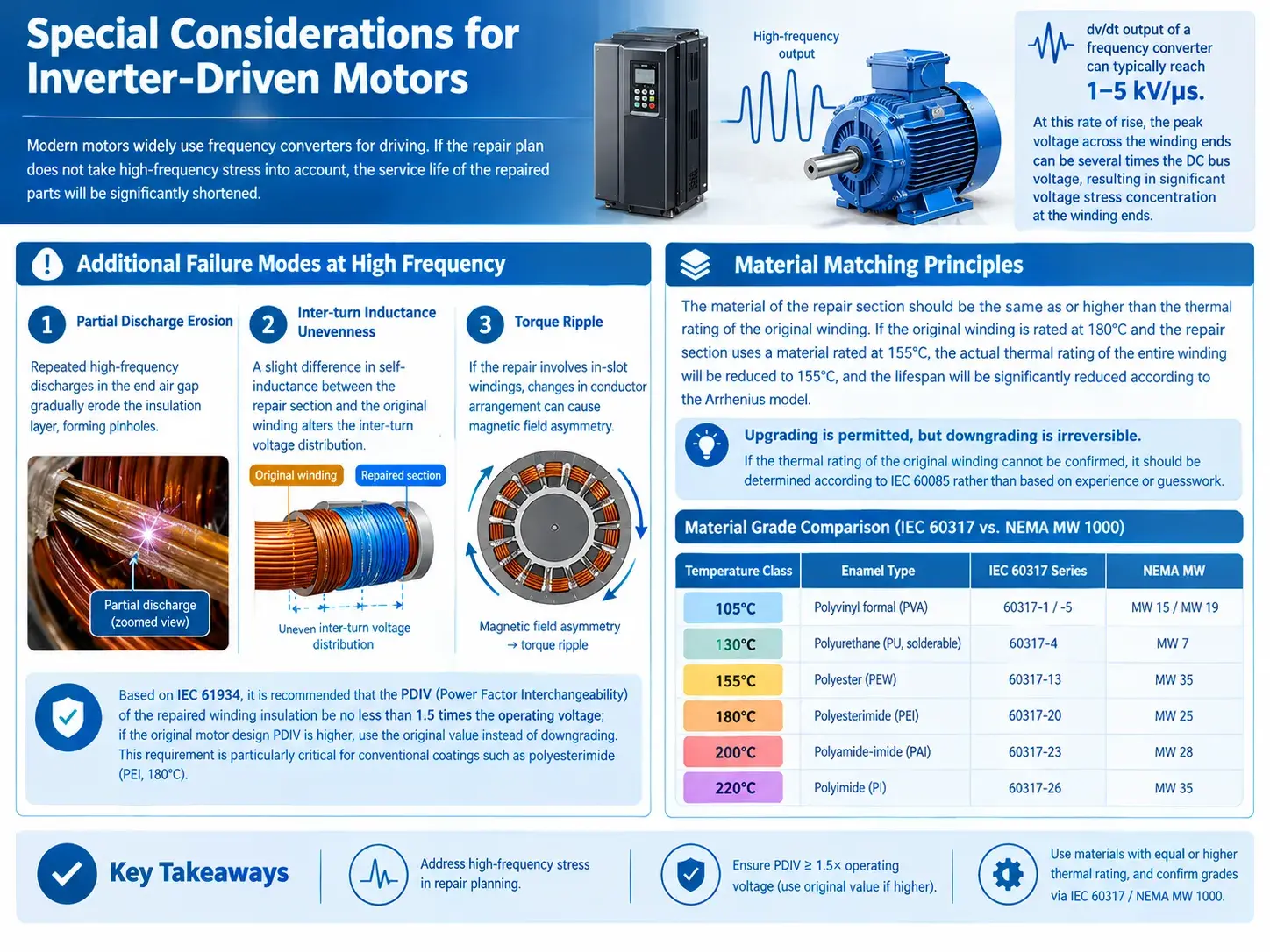
Modern motors widely use frequency converters for driving. If the repair plan does not take high-frequency stress into account, the service life of the repaired parts will be significantly shortened.
The dv/dt output of a frequency converter can typically reach 1–5 kV/μs. At this rate of rise, the peak voltage across the winding ends can be several times the DC bus voltage, resulting in significant voltage stress concentration at the winding ends.
Additional Failure Modes at High Frequency
- Partial Discharge Erosion — Repeated high-frequency discharges in the end air gap gradually erode the insulation layer, forming pinholes.
- Inter-turn inductance unevenness — A slight difference in self-inductance between the repair section and the original winding alters the inter-turn voltage distribution.
- Torque Ripple — If the repair involves in-slot windings, changes in conductor arrangement can cause magnetic field asymmetry.
Based on IEC 61934, it is recommended that the PDIV (Power Factor Interchangeability) of the repaired winding insulation be no less than 1.5 times the operating voltage; if the original motor design PDIV is higher, the original value should be used instead of downgrading. This requirement is particularly critical for conventional coatings such as polyesterimide (PEI, 180°C).
Material Matching Principles
The material of the repair section should be the same as or higher than the thermal rating of the original winding. If the original winding is rated at 180°C and the repair section uses a material rated at 155°C, the actual thermal rating of the entire winding will be reduced to 155°C, and the lifespan will be significantly reduced according to the Arrhenius model.
The standard comparison system between IEC 60317 and NEMA MW 1000 can be used to confirm material grades:
| Temperature Class | Enamel Type | IEC 60317 Series | NEMA MW |
|---|---|---|---|
| 105°C | Polyvinyl formal (PVA) | 60317-1 / -5 | MW 15 / MW 19 |
| 130°C | Polyurethane (PU, solderable) | 60317-4 | MW 7 |
| 155°C | Polyester (PEW) | 60317-13 | MW 35 |
| 180°C | Polyesterimide (PEI) | 60317-20 | MW 25 |
| 200°C | Polyamide-imide (PAI) | 60317-23 | MW 28 |
| 220°C | Polyimide (PI) | 60317-26 | MW 35 |
Upgrading is permitted, but downgrading is irreversible. If the thermal rating of the original winding cannot be confirmed, it should be determined according to IEC 60085 rather than based on experience or guesswork.
A Five-Step Decision Framework
When faced with damage to an enameled wire, the technical assessment can be summarized in five steps:
- Step 1: Identify the Damage Type — Differentiate between four types: paint film damage, conductor scratches, broken strands, and inter-turn short circuits. The repair paths for each type are completely different.
- Step Two: Quantifying Cross-sectional Loss — Measure the cross-sectional area loss rate, using 10% and 30% as boundaries to divide the temporary repair zone and the rewinding zone.
- Step 3: Determine the physical location — Distinguish between movable parts outside the slot and fixed parts inside the slot, and decide whether to use terminal crimping or vacuum impregnation.
- Step 4: Assess Operating Condition Matching — Verify the thermal rating of the original winding, the frequency converter drive operating conditions, and the insulation compatibility coefficient to determine the minimum requirements for material selection.
- Step 5: Verify Repair Quality — Complete the winding DC resistance balance test, ground insulation test, and no-load operation observation. The system can only be put into operation after all three tests are passed.
The core logic of these five steps is step-by-step convergence: from “what kind of damage is it” to “to what extent can it be repaired”. Any operation that skips the preliminary steps and directly enters the repair process may push the winding, which could have been salvaged, into irreversible damage.
Post-Repair Verification and Monitoring
Repair completion does not mean the mission is over. Without verification, the actual service condition of the repaired part cannot be determined.
Three Mandatory Tests
- DC Resistance Balance — The three-phase resistance imbalance should be controlled within 4%. Exceeding this tolerance usually indicates that the contact resistance of the repair section is too high.
- Insulation Resistance to Ground — Measure with a 500 V megohmmeter; after repair it should recover above 100 MΩ, and higher still is required when VPI is used
- No-load Operation Observation — Run the unit at no load for 10–30 minutes; it is acceptable only with no abnormal noise and no localized temperature-rise hotspot
If it is a variable frequency drive motor, it is recommended to add no-load winding voltage waveform monitoring to observe whether there are voltage spike distortions at the beginning.
Incorporate into Routine Inspection
Repaired sections should be included in the routine inspection checklist, with a focus on monitoring two indicators: winding temperature rise trend and local temperature rise distribution. The current carrying density of the repaired section is usually higher than that of the original winding, and the cumulative temperature rise effect under long-term full-load operation cannot be ignored.
For rewinding components, it is recommended to record the original design parameters (wire diameter, number of turns, slot fill factor, insulation class) to provide a basis for selection in case of subsequent damage—this point is often overlooked in actual maintenance records, leading to repeated guesswork in subsequent repairs.
Conclusion
The repair of damage to enameled copper wire motor coils is essentially an engineering judgment that balances “minimal intervention” with “ensuring reliability.” Quantifiable damage grading shifts this balance from experience-driven to data-driven; ternary system standards provide a clear baseline for material matching.
What truly determines the lifespan of a repaired component is often not the precision of the wrapping process, but whether the initial assessment was correct. When the cross-sectional loss exceeds 30%, when an inter-turn short circuit has occurred, or when the thermal rating of the repair material is lower than that of the original winding—insisting on local repairs at this point might save a few minutes, but at the cost of another downtime.