

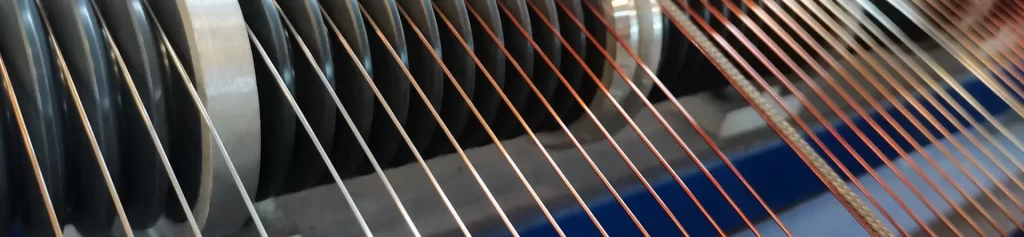
Understanding the essential nature of CCA enameled wire temperature resistance
Copper clad aluminum (CCA) enameled wire is a composite conductor made with electrolytic aluminum or electrical aluminum as the core material, an outer layer of pure copper coated through metallurgical bonding or electroplating, and an outer layer of insulating enamel coating. This structure combines the low density of aluminum with the good weldability of copper, making it an economical alternative to pure copper enameled wire in many applications.
However, when discussing “temperature resistance,” many people have a misconception: they believe that the thermal class of CCA wire is entirely determined by the enamel coating and has little to do with the conductor itself. This understanding is one-sided. The actual temperature resistance of CCA wire is the result of the combined effect of the enamel coating’s temperature resistance and the conductor structure’s thermal stability, with the limitations imposed by the conductor structure often underestimated.
This article will systematically analyze the temperature resistance of CCA enameled wire from the perspectives of conductor material properties, enamel coating system, interface bonding, and thermal cycling behavior, to help engineers make reasonable judgments when selecting a suitable model.
Clarification of Core Concepts
Nominal thermal class ≠ Actual operating temperature
The nominal thermal class of CCA enameled wire (e.g., 130°C, 155°C, 180°C, 200°C, 220°C) refers to the highest temperature that the enamel coating can withstand under standard aging test conditions, and is not equivalent to the temperature at which the winding can operate stably for a long time under actual working conditions. The actual operating temperature is limited by the weakest link among the following factors: the temperature resistance of the enamel coating, the melting point of the conductor, the interface bonding strength, and the coil heat dissipation conditions.
Temperature tolerance includes two dimensions.
- Short-term tolerance: The temperature limit under short-term overload or thermal shock, typically determined by the enamel coating breakdown temperature and interfacial bonding integrity.
- Long-term endurance: The upper limit of the steady-state temperature during continuous operation, determined by the thermal equilibrium and the material aging rate.
The limits for these two dimensions are often different and need to be evaluated separately.
Why does the CCA structure introduce additional temperature limitations?
The temperature behavior of pure copper enameled wire is only affected by two factors: copper and enamel coating, while CCA wire adds a third variable—copper-aluminum interface.
Mismatch in thermal expansion coefficients leads to interfacial stress
Copper has a coefficient of thermal expansion of approximately 16.5 ppm/°C, while aluminum has a coefficient of thermal expansion of approximately 23 ppm/°C, with aluminum being about 39% higher than copper. As temperature rises, the expansion of the outer copper layer and the inner aluminum core is asynchronous, creating mechanical stress at the interface. Repeated thermal cycling gradually decreases the interface bonding strength, and in extreme cases, localized delamination or fusion may occur between the copper layer and the aluminum core.
Aluminum cores have lower melting points.
Aluminum has a melting point of approximately 660°C, significantly lower than copper’s 1083°C. Under severe overload or short-circuit conditions, the aluminum core will melt before the copper layer, leading to complete failure of the winding. This is why CCA lines are not suitable for high-current, high-reliability applications.
Lower conductivity leads to more heat generation.
The conductivity of CCA wire is approximately 60-68% IACS, far lower than that of pure copper (100%). At the same current density, CCA wire has higher I²R losses and generates more heat, which is detrimental to the temperature balance of the winding.
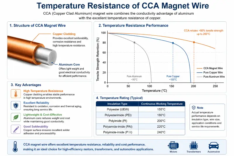
CCA enameled wire Conductor Material Properties and Temperature Resistance
The triangular relationship between density, conductivity, and thermal resistance
The core characteristic of CCA wire is its low density (3.2-3.6 g/cm³, approximately 36-40% of that of pure copper), but its conductivity is only 62-64% IACS. This combination of properties leads to a thermodynamic dilemma:
Advantages of Low Density
- winding Lighter weight makes it attractive for weight-sensitive applications such as mobile devices, electric vehicles, and aerospace.
- More turns can be wound for the same outer diameter, which helps to increase the turn density.
The cost of low conductivity
- Under the same current, the resistance increases by 56-74%, and the I²R loss increases significantly.
- Steady-state temperature rise is measured to be 15-40 K higher than that of pure copper.
- The current density must be designed with derating in mind; otherwise, the temperature rise will exceed the tolerance range of the enamel coating.
The effect of decreased thermal conductivity
Pure copper has a thermal conductivity of approximately 401 W/(m·K), while CCA wire has only about 230 W/(m·K), which is about 43% lower than pure copper. This reduced heat dissipation capacity means that heat accumulates more quickly inside the coil, further increasing the temperature.
Conductor melting point and overload capacity
The internal aluminum core of the CCA wire has a melting point of approximately 660°C, while the external copper layer has a melting point of 1083°C. This structure presents a unique risk under overload conditions: the aluminum core softens or melts first, while the external copper layer remains intact, resulting in an abnormal state where the windings are encased in a copper shell covering liquid aluminum.
The consequences of this state include:
– The probability of an inter-turn short circuit increases significantly.
– The copper casing may deform or crack under high temperatures due to loss of support.
Molten aluminum may splatter, causing damage to adjacent components.
In contrast, pure copper wires heat up and soften as a whole when overloaded. Although they are also damaged, the failure mode is relatively mild.
Temperature sensitivity of interface bonding quality
The strength and conductivity of CCA wires are highly dependent on the bonding quality of the copper-aluminum interface. A qualified CCA wire should show no delamination or cracks in the bonding strength test.
Under temperature cycling conditions, the interfacial bonding quality gradually deteriorates:
- Normal operating conditions (-40°C to +130°C): Interface stress is relatively low, and the bonding strength remains largely intact.
High-temperature conditions (above 130°C): Aluminum’s creep begins to manifest, microcracks appear at the interface, and bonding strength decreases. - Extreme operating conditions (above 180°C): Significant interface degradation may occur, potentially leading to localized delamination.
Therefore, the actual usable temperature limit of CCA wire is usually 20-30°C lower than that of pure copper wire of the same grade.
CCA enameled wire enamel coating system matches thermal class
Common enamel coating types and thermal classes
Based on the product portfolios of mainstream manufacturers, the available enamel coating types and thermal class for CCA enameled wire are as follows:
130°C thermal classenamel coating system
– models: PEW/130, UEW/130
– enamel coating type: polyester (PEW), polyurethane (UEW)
– Features: Good solventability, low cost
– Applicable scenarios: small motors, low-temperature operating conditions transformer
155°C thermal classenamel coating system
– models: PEW/155, UEW/155
– enamel coating type: modified polyester (PEW(W)-1), weldable polyurethane (UEW/155)
– Features: Improved heat resistance, maintained solventability
– Applicable scenarios: General household appliance motors, medium-temperature operating conditions transformer
180°C thermal classenamel coating system
– models: EIW/180, UEW/180
– enamel coating types: polyester imine (EIW), modified polyurethane (UEW/180)
– Features: thermal class significantly improves performance
– Applicable scenarios: High-temperature motors, automotive electronics
200°C thermal classenamel coating system
– models:EIW/AIW/200
– enamel coating type: polyester imine/polyamide-imide composite (EIW/AIW)
– Features: Double-layer enamel coating structure, excellent chemical resistance
– Applicable scenarios: High-frequency transformer, special operating condition coils
220°C and above thermal class enamel coating system
– models:EIW(EI/AIW)/220
– enamel coating type: Multilayer polyimide composite
– Features: Extreme heat resistance, high cost
– Applicable scenarios: military, aerospace, special high-temperature equipment
CCA enameled wire enamel coating System Quick Reference Table
| enamel coatingmodels | thermal class | enamel coating type | enamel coating level | Typical application scenarios |
|---|---|---|---|---|
| PEW/130, UEW/130 | 130°C | polyester、polyurethane | Grade 1/2/3 | Small motors, low-temperature transformers |
| PEW/155, UEW/155 | 155°C | Modified polyester, weldable polyurethane | Grade 1/2/3 | Conventional household appliance motors, medium-temperature transformers |
| EIW/180, UEW/180 | 180°C | polyesterimine, modified polyurethane | Grade 1/2/3 | High-temperature motors, automotive electronics |
| EIW/AIW/200 | 200°C | polyesterimine/polyamide-imide complex | Grade 1/2/3 | High-frequency transformer coils and special operating condition coils |
| EIW/AIW/220 | 220°C | Multilayer polyimide composite | Grade 1/2/3 | Military industry, aerospace, special high-temperature equipment |
The effect of enamel coating grade on temperature resistance
The enamel coating thickness is graded as Grade 1/Grade 2/Grade 3, directly affecting the winding space and heat dissipation capability.
- Grade 1: Thin enamel coating, high winding density, relatively good heat dissipation, but small insulation margin.
- Grade 2: Standard enamel coating, performance and density balanced
Grade 3: Thick enamel coating, high insulation reliability, but poorer heat dissipation; winding temperature rise may increase by 5-10 K.
Under high-temperature conditions, Grade 2 or Grade 3 should be given priority because the mechanical strength of thin enamel coatings decreases more rapidly at high temperatures.
Correction between thermal class and actual operating temperature
The thermal class stated by the manufacturer is a value under standard experimental conditions and needs to be corrected for practical applications.
ambient temperature correction
If the actual working environment temperature is higher than the standard test environment (usually 23°C ± 2°C), the insulation aging rate will roughly double for every 10°C increase.
Temperature rise margin requirement
Based on engineering experience, the steady-state temperature rise of the winding should be controlled within 50-60% of the nominal temperature to obtain sufficient lifespan margin. For example, for a 130°C thermal class CCA line, the actual steady-state operating temperature is recommended not to exceed 65-78°C.
Design Life Correction
If a design life of 20-30 years is required, instead of the standard 10-15 years, then the operating temperature needs to be further increased by 10-15°C.
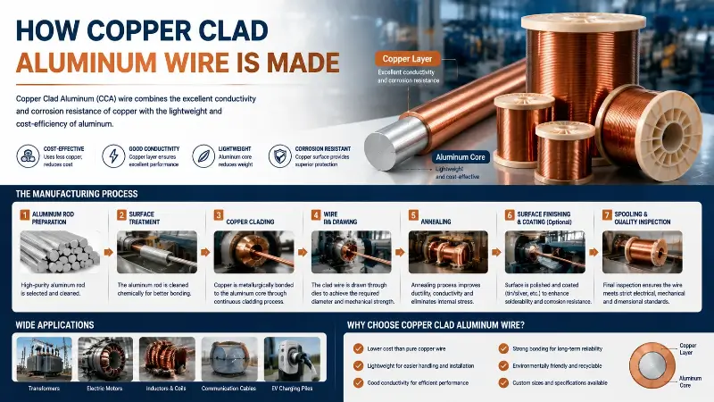
Thermodynamic behavior and failure modes of the copper-aluminum interface
Mechanism of interfacial thermal expansion stress
When the CCA line cools from the manufacturing temperature to the operating temperature, or experiences temperature fluctuations during operation, the copper layer and the aluminum core tend to shift relative to each other due to the difference in their coefficients of thermal expansion (16.5 vs 23 ppm/°C). This shift creates mechanical stress at the interface.
Stress Estimation
Taking a 1.0 mm diameter CCA line as an example, the thickness of the copper layer is approximately 0.05-0.1 mm. If the temperature changes by 100°C, the relative displacement between the copper layer and the aluminum core is approximately 0.65 ppm/°C × 100°C × 0.1 mm = 0.0065 mm. Although this displacement is small, it will accumulate into interfacial cracks under repeated thermal cycling.
Location of stress concentration
The interfacial stress is mainly concentrated in:
– Copper-aluminum bonding transition zone (metallurgical bonding transition layer)
– copper layer Surface defects (such as uneven coating, scratches)
– Stress concentration effect at wire bends
Interface degradation and delamination
Under temperature cycling, the interface may undergo the following degradation process:
Phase 1: Initial Stage (<100 thermal cycling sessions)
– The interfacial stress remains within the elastic range and shows no significant change.
– bonding strength remains basically maintained.
Phase 2: Mid-term (100-500 thermal cycling sessions)
– Aluminum’s creep begins to accumulate.
Microscopic cracks appeared on the interface.
– bonding strength decreases by 10-30%
Phase 3: Later Stage (>500 thermal cycling cycles)
– Microcrack propagation and convergence
– Local delamination or delamination occurs.
– bonding strength decreased by more than 50%
interface degradation can lead to increased contact resistance and localized heating, creating a vicious cycle.
The exacerbation of electrochemical corrosion
In humid environments, the electrochemical potential of aluminum (-1.66 V vs SHE) is much lower than that of copper (+0.34 V vs SHE), and direct contact between the two will form a galvanic cell. Aluminum, acting as the anode, preferentially corrodes, and the resulting alumina layer is insulating, significantly increasing the contact resistance.
At high temperatures, moisture evaporation accelerates, increasing the corrosion rate. The expansion of corrosion products further exacerbates interfacial stress.
Preventive Measures:
– Control ambient humidity
– Using sealing technology
– Regularly check the interface status
Methods for detecting interface failures
bonding strength test
– Peel strength test (force required to peel off the copper layer)
– Examine the cross-section under a microscope to check for obvious cracks.
Resistance Test
– Measure the DC resistance of the wire and compare it with the theoretical value.
– An abnormally high resistance may indicate an interface problem.
Metallographic analysis
– Take samples for metallographic section analysis
– Observe the morphology and defect distribution of the copper-aluminum interface
Temperature performance of CCA enameled wire under different operating conditions
CCA Temperature Performance under Different Frequency Operating Conditions
| Operating frequency | Resistance performance | temperature rise performance | Engineering Judgment |
|---|---|---|---|
| 50/60 Hz power frequency | 56-74% higher than pure copper | 15-40 K higher than pure copper | Low current density is enabled, high density is disabled. |
| Intermediate frequency 400 Hz-10 kHz | The proximity effect begins to appear. | Slightly higher than pure copper | Actual measurements are required; estimations based on DC voltage are not acceptable. |
| High frequency 15-350 kHz | AC resistance is lower than that of pure copper | Superior to pure copper | CCA Advantage Range |
| High frequency >100 kHz | At 60 kHz, it is approximately 70% of copper. | Significantly lower than pure copper | High-frequency transformers and inductors are preferred. |
Extreme environmental conditions
High-temperature environment (>150°C)
– interface degradation accelerated
– We recommend choosing an enamel coating rating of 200°C or higher.
– The actual operating temperature still needs to be strictly controlled.
Low Temperature Environment (< -40°C)
– The enamel coating becomes brittle, resulting in decreased mechanical properties.
– Avoid impacts during winding and assembly.
– Interface bonding strength decreased slightly but is acceptable.
High humidity environment
Increased risk of electrochemical corrosion
– A sealing or protective coating is required.
Vibration Environment
The aluminum core is relatively brittle, and long-term vibration may cause internal microcracks.
Applications such as automobiles and power tools require special evaluation.
Comparison of temperature resistance between CCA enameled wire and pure copper enameled wire
Nominal thermal class comparison
Although CCA wires and pure copper wires can use the same thermal class enamel coating, their actual usable temperature ranges differ.
| thermal class | enamel coatingmodels | CCA practical recommendation operating temperature | Recommended operating temperature for pure copper |
|---|---|---|---|
| 130°C | PEW/130 | 60-75°C | 75-90°C |
| 155°C | PEW/155 | 70-85°C | 85-105°C |
| 180°C | EIW/180 | 80-100°C | 100-125°C |
| 200°C | EIW/AIW/200 | 90-115°C | 115-140°C |
| 220°C | EIW/220 | 100-130°C | 130-160°C |
As can be seen from the table above, the actual usable temperature of CCA wire is about 15-25°C lower than that of pure copper wire of the same grade. This difference comes from the combined effects of conductor melting point, interface stability, and heat dissipation capability.
Comparison of long-term aging characteristics
Aging Mechanism of Pure Copper Wire
– Primarily the thermo-oxidative aging of the enamel coating.
The aging rate is affected by temperature; it approximately doubles for every 10°C increase in temperature.
– Performance degradation is relatively linear
CCA Wire Aging Mechanism
In addition to enamel coating aging, there is also interface degradation.
– The rate of interface degradation accelerates at high temperatures.
– Sudden failure may occur (interface cracks suddenly propagate).
– Failure modes are more complex than those of pure copper wires.
Aging Curve Characteristics
The performance degradation of pure copper wire exhibits a smooth, downward curve. However, CCA wire can experience “cliff-like” failure—after long-term operation, the interface suddenly reaches a critical state, leading to a sharp decline in performance. This failure mode is more detrimental to reliability assessment.
Comparison of short circuit withstand capabilities
Short-circuit behavior of pure copper wire
When a short-circuit current flows, the resistor heats up, causing the temperature to rise rapidly.
– Copper has a melting point of 1083°C; the copper wire will melt and break during a short circuit.
– The circuit breaker has a relatively long trip time, usually from a few seconds to tens of seconds.
Short-circuit behavior of the CCA line
– Higher resistance, faster heat generation
– aluminum core has a melting point of 660°C, much lower than that of copper.
– The aluminum core is first softened or melted to disrupt the winding structure.
– May lead to expansion of the inter-turn short circuit.
Conclusion: CCA wires have significantly weaker short circuit withstand capability than pure copper wires and are not suitable for applications with a risk of short circuits.
Quantitative analysis of the temperature rise comparison
Taking a 0.5 mm diameter enameled wire, 10 A current, and natural cooling conditions as an example:
Pure copper wire
– Cross-sectional area approximately 0.196 mm²
– current densityapproximately 51 A/mm²
– Resistance approximately 0.0878 Ω/100mΩ
– temperature rise Approximately 45°C (typical value)
CCA line (62% IACS)
– Resistance approximately 0.1416 Ω/100mΩ
– Losses increased by 61%
– Temperature rise: approximately 70-75°C (estimated, taking into account heat dissipation).
This means that under the same current, the temperature rise of CCA wire may be 25-30°C higher than that of pure copper wire. For a nominal 130°C thermal class enamel coating, pure copper wire still has a margin, but CCA wire is already close to its design limit.
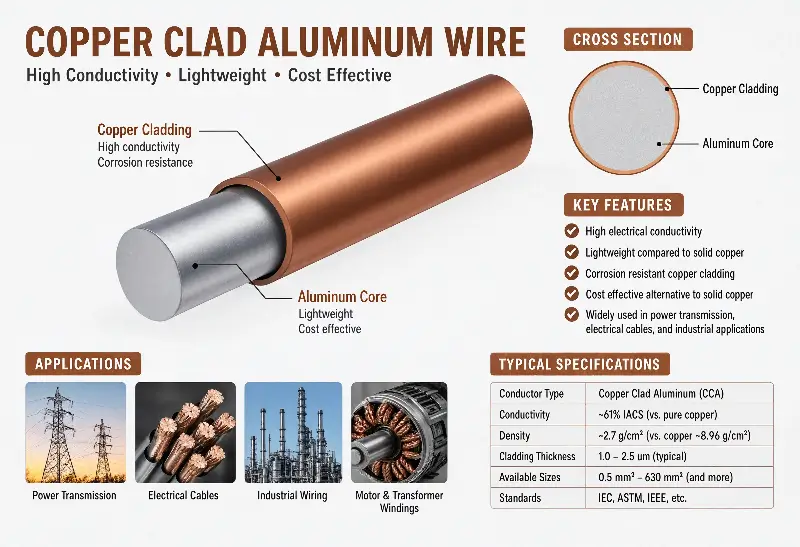
Selection Decision and Verification Methods in High Temperature Scenarios
Material selection strategies for different temperature ranges
Temperature < 80°C
– ✅ CCA cables are safe to use.
– Significant economic advantages
– Common household appliances such as motors and speakers
Temperature 80-120°C
– ⚠️ Requires careful evaluation
– Select 155°C or higher thermal classenamel coating
– Temperature rise must be verified by actual measurement.
– Note the current density derating.
Temperature 120-150°C
– ❌ Generally, the use of CCA wires is not recommended.
High temperatures accelerate interface degradation.
– High reliability risk
– It is recommended to use pure copper or aluminum wire instead.
Temperature > 150°C
– ❌❌ CCA wires are strictly prohibited.
– The interface is nearing its failure threshold.
– Pure copper wire with EIW/AIW/220 or higher enamel coating should be selected.
– Or use special materials such as nickel-chromium alloy wire.
Derating design of current density
Because CCA lines have low conductivity and poor heat dissipation, current density must be strictly controlled during the design process.
Recommended Limit for current density
– Standard motor (winding): ≤3 A/mm²
– transformerwinding:≤2.5 A/mm²
– High-frequency applications (>15 kHz): The restrictions can be relaxed appropriately, as the skin effect is actually beneficial.
Calculation of the wire diameter after derating
– When switching from pure copper to CCA, the wire diameter typically needs to be increased by approximately 20-30%.
For example, if 0.5 mm pure copper wire was used previously, switching to CCA might require 0.63 mm.
However, increasing the wire diameter will occupy more slot space, which needs to be considered comprehensively.
Temperature verification test method
Temperature Rise Test
– Compliant with IEC 60034-1 or NEMA MG-1 standards
– Measure the change in resistance and calculate the temperature rise.
– ambient temperature 40°C, operate at rated load until thermal stability
thermal aging experiment
– Place at the nominal temperature for a predetermined time
– Regularly measure the thickness and hardness of the enamel coating.
– Observe the interface integration status
thermal cycling experiment
– Simulate actual temperature fluctuations
– The number of cycles is determined based on the actual working conditions.
– Check the interface delamination status after the experiment.
Accelerated aging test
– Accelerated aging under conditions above the nominal temperature
– Calculating actual lifespan using the Arrhenius equation
– Note that the failure mechanism of CCA wires differs from that of pure copper wires; extrapolation should be made with caution.
Engineering Boundaries and Selection Principles of CCA enameled wire
The temperature resistance of CCA enameled wire is essentially a balance between cost advantage and temperature reliability. Its nominal thermal class is determined by the enamel coating system, but the actual usable temperature is limited by multiple factors including conductor melting point, interface stability, heat dissipation capability, and current density. At a nominal thermal class of 130°C, the actual recommended operating temperature of CCA wire is only 60-75°C, approximately 15-25°C lower than equivalent pure copper wire. When the temperature exceeds 120°C, the risks of interface degradation and aluminum core softening render CCA wire unsuitable, making pure copper or other high-temperature materials a more reliable choice.
The temperature performance of CCA wires is highly dependent on frequency characteristics, which is one of the most fundamental differences between them and pure copper wires. In the power frequency and low-to-mid-frequency range, CCA wires generate more heat due to their lower conductivity, resulting in a significantly higher temperature rise than pure copper wires. However, in the high-frequency range of 15-350 kHz, the skin effect concentrates current in the copper layer, leading to lower AC resistance compared to pure copper, reaching as low as 70% at 60 kHz. This characteristic gives CCA wires unique advantages in high-frequency transformers, switching power supply inductors, and wireless charging coils, while their use should be cautious or avoided in low-frequency, high-current applications.
In engineering practice, judging temperature tolerance cannot rely solely on the nominal thermal class; it must comprehensively consider three core dimensions: conductor characteristics, interface stability, heat dissipation conditions, and current density. When making selection decisions: first, clearly define the actual operating temperature and environmental conditions to determine the required enamel coating level; second, assess the current density to ensure that the temperature rise does not exceed the design value; and finally, verify the interface quality, including bonding strength and resistance testing. Only when all three dimensions are simultaneously satisfied can the CCA wire reliably operate within its application boundaries. Furthermore, for operating conditions exceeding 150°C or high-current, low-frequency applications, pure copper wire remains the only reliable choice.