

After enameled wire is wound, the enamel coating at the ends must be removed before welding, crimping, or terminal connections can be made. This seemingly simple process actually determines the conductivity, mechanical strength, and long-term reliability of the joint. However, in actual maintenance and production sites, the choice of enamel removal method often faces a dilemma: chemical enamel removal, while highly efficient, is limited by volatile organic compound emissions, hazardous waste disposal, and workshop ventilation conditions; while physical methods, although environmentally friendly, require operators to accurately grasp the temperature window and mechanical boundaries to avoid damaging the conductor.
This article focuses on two completely solvent-free paint stripping methods—heat-based and mechanical—and systematically compares their principles, applicable paint film types, temperature and force parameters, conductor protection mechanisms, and economics. It also provides a practical selection decision matrix, offering clear process guidance for motor repair, transformer rewinding, small-batch trial production, and large-scale production lines.
For a broader overview of all available approaches—including solvent immersion, thermal stripping, and mechanical abrasion—see our companion guide, How to Strip Enameled Copper Wire Safely. This article focuses exclusively on the chemical-free subset. For coating thickness selection before stripping, see Enameled Copper Clad Aluminum Wire Specifications Guide.
The Engineering Reality of Enamel Stripping and Its Failure Chains
Stripping is not as simple as “removing a layer of enamel.” The insulation layer of enameled wire is typically only 15–80 μm thick (Grade 1/2/3), beneath which lies a copper or aluminum conductor with a diameter of 0.1–2.5 mm. The stripping process is essentially about finding an operational window between two adjacent failure boundaries: on one side, “residual enamel leads to increased contact resistance and poor solder joints,” and on the other side, “conductor damage leads to decreased tensile strength, localized heating, or even insulation breakdown.”
To understand this essence, we need to first identify the three failed links:
| Failure Chain | Trigger Condition | Consequence | Typical Scenario |
|---|---|---|---|
| Contact failure | Enamel residue exceeding 5% of the circumference | Increased contact resistance, cold solder joints, early solder joint cracking | Lead terminal soldering, sensor leads |
| Conductor failure | Excessive scraping, scratches, annealing softening | Tensile strength reduced by more than 30%, localized heating, insulation breakdown | Fine wire gauge (30 AWG and above) coil rewinding |
| Process failure | Insufficient or excessive temperature, uncontrolled dwell time | Enamel charring residue, copper oxidation and blackening | Batch production consistency control |
NEMA MW 1000-2018 provides a clear quantitative threshold for scrape resistance: the lowest and average failure loads in any three tests must not be lower than the values specified in Table 48. This means that if a considerable thickness of copper layer has been removed from the conductor surface after stripping, it has already deviated from the mechanical integrity promised by the original design. The abrasion resistance ratings for Grade 1/2/3 of 0.250–2.500 mm grade 120 polyvinyl acetal winding wire are designed precisely for this purpose—the “mechanical budget” consumed during the stripping process is limited.
Therefore, the evaluation of a paint stripping solution cannot stop at the level of “can it be removed?”, but must answer three questions: How much paint film can be removed with almost no damage to the conductor? Does the temperature exceed the thermal decomposition threshold of the paint film or the annealing threshold of copper? Can the residue be completely removed before soldering?
The Full Spectrum of Chemical-Free Enamel Stripping Technologies
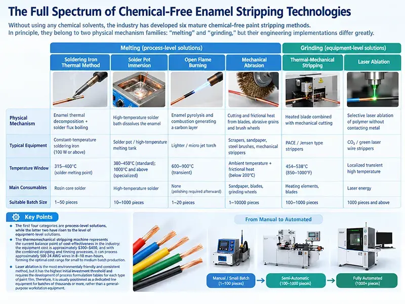
Without using any chemical solvents, the industry has developed six mature chemical-free paint stripping methods. In principle, they belong to two physical mechanism families: “melting” and “grinding,” but their engineering implementations differ greatly.
| Technique | Physical Mechanism | Typical Equipment | Temperature Window | Main Consumables | Suitable Batch Size |
|---|---|---|---|---|---|
| Soldering Iron Thermal Method | Enamel thermal decomposition + solder flux boiling | Constant-temperature soldering iron (100 W or above) | 315–400°C (solder melting point) | Rosin core solder | 1–50 pieces |
| Solder Pot Immersion | High-temperature solder bath dissolves the enamel | Solder pot / high-temperature melting tank | 380–450°C (standard); 1000°C and above (specialized) | High-temperature solder | 10–1000 pieces |
| Open Flame Burning | Enamel pyrolysis and combustion generating a carbon layer | Lighter / micro jet torch | 600–900°C (transient) | None (polishing required afterward) | 1–20 pieces |
| Mechanical Abrasion | Cutting and frictional heat from blades, abrasive grains and brush wheels | Scrapers, sandpaper, steel brushes, mechanical strippers | Ambient temperature + frictional heat (below 200°C) | Sandpaper, blades, grinding wheels | 1–10000 pieces |
| Thermal-Mechanical Stripping | Heated blade combined with mechanical cutting | PACE / Jensen type strippers | 454–538°C (850–1000°F) | Heating elements, blades | 100–1000 pieces |
| Laser Ablation | Selective laser ablation of polymer without contacting metal | CO₂ / green laser wire strippers | Localized transient high temperature | Laser energy | 1000 pieces and above |
It should be noted that the first four categories belong to process-level solutions, while the latter two have risen to the level of equipment-level solutions. Among them, the thermomechanical stripping machine represents the current balance point of cost-effectiveness in the industry: the equipment cost is approximately $300–$400, and with the combined stripping and tinning processes, it can process approximately 500 24 AWG wires in 8–10 man-hours, forming the optimal cost range for small to medium batch production.
While laser ablation is the most environmentally friendly and consistent method, it has the highest initial investment threshold and requires the development of process formulation tables for each type of paint film. Therefore, it is usually positioned as a dedicated line equipment for batches of thousands or more, rather than a general-purpose workstation equipment.
Heat-Based Stripping: Principles, Parameters and Process Essentials
Soldering Iron Thermal Method: The Top Choice for Solderable Enamel
The reason why the hot-melt soldering method is so popular in repair scenarios is that the enamel coating itself is “solderable” (solder-through). Taking Class 130 polyurethane enameled wire as an example, its enamel coating begins to soften at temperatures above 130°C. When a high-temperature soldering iron of 315–400°C is applied with fresh rosin-core solder, the active ingredients in the flux catalyze the decomposition of the enamel coating. The decomposition products are carried away by the boiling solder, thus exposing a bare copper surface that can be directly tinned within seconds.
The core parameters and key points of this method are as follows:
| Parameter | Recommended Value and Requirements | Explanation |
|---|---|---|
| Soldering iron power | 100 W or above | Insufficient power causes slow heating; the solder cannot boil and carry away the enamel residue, producing a false connection |
| Soldering tip temperature | 315–400°C | Depends on the solder alloy: 63/37 tin-lead 183°C, SAC305 lead-free 217°C; actual temperature must be at least 100°C above the melting point |
| Solder condition | Must be fresh with an active rosin core | Oxidized solder loses fluxing capacity and cannot carry away the enamel decomposition products |
| Single-point dwell time | 3–10 seconds | Adjust according to wire diameter and coating thickness; do not exceed 5 seconds on fine wires |
| Subsequent action | Tin immediately | Bare copper begins oxidizing within minutes of exposure, compromising solder joint reliability |
| Solder Pot Type | Temperature Range | Suitable Enamel | Risk Level |
|---|---|---|---|
| Standard solder pot | 225–260°C | Not usable for stripping; only for tinning already-stripped wire | None |
| High-temperature solder pot (specialized) | 380–450°C | Polyurethane (PU), polyvinyl acetal (PVA/Formvar) | Medium: possible light copper surface oxidation |
| Ultra-high-temperature solder pot | 1000°C and above | Polyimide (PI/Kapton) and other refractory coatings | High: risk of excessive copper oxidation; dwell time must be shortened |
For non-soldering enamel coatings such as polyester (PEW, Class 155), polyesterimide (PEI, Class 180), polyamide-imide (PAI, Class 200), and even polyimide (PI, Class 220 and above), the soldering iron method is essentially ineffective—the coating will not decompose within the solder’s boiling point, only forming a charred, carbonized residue. Therefore, the only reliable basis for determining whether the soldering iron method can be used is the coating type, not increasing the temperature: the temperature can be increased, but the decomposition temperature of PI coatings is far higher than the limit achievable by any soldering iron.
Solder Pot Immersion: The Temperature Trap in Batch Pretreatment
The solder pot method is one of the most misunderstood processes. The standard solder pot’s operating temperature (225–260°C) is insufficient for removing the enamel coating—this is the most common misconception in the industry. The proper purpose of a solder pot is to solder already stripped of enamel, not to remove the enamel itself.
The solder pot used for actual paint stripping must be processed using a high-temperature process:
| Enamel Type | Recommended Stripping Temperature | Explanation |
|---|---|---|
| Polyurethane (PU, Class 105–130) | 454–538°C (850–1000°F) | Standard thermal stripper operating range; the process is highly mature |
| Polyvinyl acetal (PVA/Formvar, Class 105–120) | 454–538°C | Below the 175°C heat shock limit specified by NEMA MW 1000, providing an ample safety margin |
| Polyester (PEW/PEI, Class 155–180) | Above 538°C | Higher temperature or extended heating time required |
| Polyimide (PI/Kapton, Class 220 and above) | Above 1000°C, or switch to chemical and laser methods | Thermal methods alone are usually ineffective |
The advantage of the high-temperature tin pot method lies in its excellent consistency—the entire batch of conductors is treated under the same thermal process, resulting in a highly uniform coating residue, and it can be combined with subsequent tinning processes into a single immersion. Industrial practice shows that the tin pot method, combined with 63/37 tin-lead alloy or SAC305 lead-free solder at 360–400°C and an immersion time of 1–2 seconds, can achieve reliable wetting results.
The main limitation is that the upper temperature limit is constrained by the oxidation behavior of copper: once the temperature exceeds 500°C, a cuprous oxide (Cu₂O) black film quickly forms on the copper surface, which must be removed by subsequent acid pickling or strong flux; otherwise, it will directly affect the strength of the solder joint. This is why removing PI (Kapton) type coatings from solder pots is considered a high-risk operation in practice.
Open Flame Burning: The Only Option for Emergency Field Work
The open flame method is suitable for emergency repairs in the field, when there is no power supply, or when there is only a very small number of wires. The principle is to cause the paint film to pyrolyze and burn instantly at 600–900°C, generating a loose carbon layer, which can then be removed by physical wiping.
Practical tips are extremely important, and the consensus from front-line engineering experience is:
- The wire does not need to be heated until it glows red — it is sufficient to let the enamel coating ignite, then continue heating for another 1–2 seconds after the flame is extinguished. Overheating will anneal the copper and make it brittle.
- Use a lighter or a torch, never matches — matches burn for too short a time and deliver discontinuous heat, which cannot strip enamel evenly.
- Residue must be cleaned with flux after burning — rosin-based flux (RMA) effectively dissolves and carries away the carbon film.
- Quench the wire in methylated spirits once it has turned dark red — thermal shock separates the carbon layer from the copper surface, so the residue flakes off on its own, which substantially reduces the manual wiping effort that follows.
- Wipe in one direction only — use an eraser or steel wool moving from the wire end in a single direction, never back and forth, so that carbon debris is not pressed back onto the conductor surface.
Thermal-Mechanical Strippers: The Industrial Temperature Window
Thermomechanical paint stripping machines are currently the optimal industrial solution for mass paint stripping. They combine heating elements with rotating blades: heat softens or embrittles the paint film, which is then mechanically removed by the blades.
Temperature window is a core technical parameter of this process:
NEMA MW 1000-2018 specifies the following thermal shock test conditions for PVA coatings: 175°C, no visible cracks in the coating; and a median thermoplastic flow temperature not lower than 180°C. These data confirm from a standard perspective that as long as the paint removal temperature is controlled below 500°C and the dwell time is on the order of a few seconds, the thermal integrity of the PVA coating will not be compromised.
Regarding applicable wire gauges, high-quality thermal stripping machines can reliably handle 10–30 AWG; for gauges below 30 AWG (i.e., diameter less than approximately 0.255 mm), laser or chemical methods are preferred to avoid deformation or breakage of the fine wire under the combined effects of mechanical and thermal forces. Some advanced models (such as the SIENNA MWS) can extend the processing capacity to 44 AWG.
Mechanical Stripping: Precision, Cost and Conductor Protection
Scrapers and Sandpaper: Lowest Cost, Highest Skill Demand
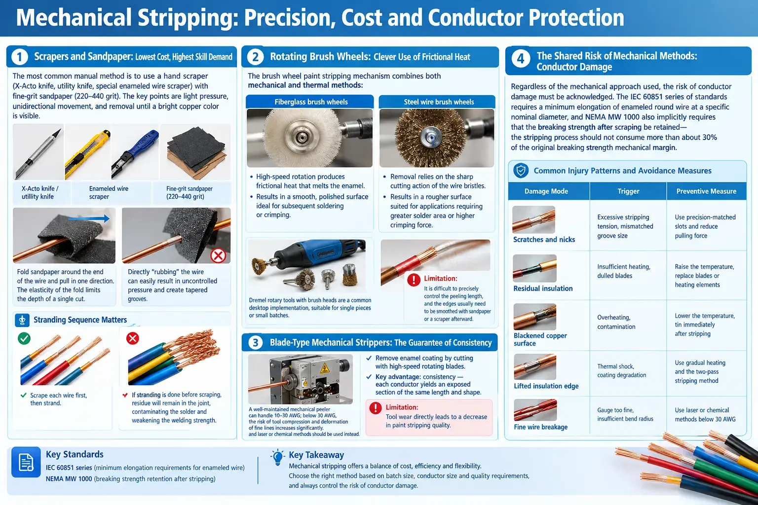
The most common manual method is to use a hand scraper (X-Acto knife, utility knife, special enameled wire scraper) with fine-grit sandpaper (220–440 grit). The key points are light pressure, unidirectional movement, and removal until a bright copper color is visible.
Folding sandpaper around the end of the wire and pulling it in one direction is the most effective way to control the force—the elasticity created by the fold limits the depth of a single cut. In contrast, directly “rubbing” the wire with sandpaper can easily result in uncontrolled pressure and create tapered grooves.
The stranding sequence has a decisive impact on the result: Each wire should be scraped off before stranding. If stranding is done before scraping, the wire will bend continuously at the contact point away from the scraping surface. Not only is it difficult to control the exposed area, but a large amount of paint residue will also remain in the joint, contaminating the solder and weakening the welding strength.
Rotating Brush Wheels: Clever Use of Frictional Heat
The brush wheel paint stripping mechanism combines both mechanical and thermal methods:
- Fiberglass brush wheels: high-speed rotation produces frictional heat that melts the enamel, resulting in a smooth, polished surface ideal for subsequent soldering or crimping.
- Steel wire brush wheels: removal relies on the sharp cutting action of the wire bristles, resulting in a rougher surface suited to applications requiring greater solder area or higher crimping force.
Dremel rotary tools with brush heads are a common desktop implementation, suitable for single pieces or small batches. The limitation of brush wheel peeling is that it is difficult to precisely control the peeling length, and the edges usually need to be smoothed with sandpaper or a scraper afterward.
Blade-Type Mechanical Strippers: The Guarantee of Consistency
Blade strippers remove the enamel coating from the surface of conductors by cutting with high-speed rotating blades. Their key advantage over manual scraping is consistency—each conductor yields an exposed section of the same length and shape.
Its limitations are also clear: tool wear directly leads to a decrease in paint stripping quality. A well-maintained mechanical peeler can handle 10–30 AWG; below 30 AWG, the risk of tool compression and deformation of fine lines increases significantly, and laser or chemical methods should be used instead.
The Shared Risk of Mechanical Methods: Conductor Damage
Regardless of the mechanical approach used, the risk of conductor damage must be acknowledged. The IEC 60851 series of standards requires a minimum elongation of enameled round wire at a specific nominal diameter, and NEMA MW 1000 also implicitly requires that the breaking strength after scraping be retained—the stripping process should not consume more than about 30% of the original breaking strength mechanical margin.
Common injury patterns and avoidance measures:
| Damage Mode | Trigger | Preventive Measure |
|---|---|---|
| Scratches and nicks | Excessive stripping tension, mismatched groove size | Use precision-matched slots and reduce pulling force |
| Residual insulation | Insufficient heating, dulled blades | Raise the temperature, replace blades or heating elements |
| Blackened copper surface | Overheating, contamination | Lower the temperature, tin immediately after stripping |
| Lifted insulation edge | Thermal shock, coating degradation | Use gradual heating and the two-pass stripping method |
| Fine wire breakage | Gauge too fine, insufficient bend radius | Use laser or chemical methods below 30 AWG |
A Systematic Comparison of Heat-Based and Mechanical Methods
A Twelve-Dimension Quantitative Comparison
| Comparison Dimension | Heat-Based Stripping | Mechanical Stripping |
|---|---|---|
| Mechanism of action | Melting, thermal decomposition, combustion | Cutting, abrasive friction |
| Temperature range | 315°C (soldering iron) to above 1000°C (PI coatings) | Ambient temperature; frictional heat usually below 200°C |
| Effect on the copper conductor | High temperatures may cause oxidation or annealing softening | Direct cutting may scratch the surface or reduce the effective cross-section |
| Consistency of stripping | High for batch equipment; moderate for the manual soldering iron method | High for blade-type equipment; low for hand scrapers |
| Precision of the stripping boundary | Blurred boundaries with hot methods, requiring subsequent trimming | Clear boundaries with controllable position |
| Surface quality | Bright with the soldering iron method; carbon residue from open flame requires polishing | Rough with steel wire brushes, smooth with fiberglass brushes |
| Applicable enamel types | Optimal for solderable PU; PI requires extremely high temperatures | Applicable to virtually all enamel types |
| Fiber covered wire | Not applicable; the fiber layer must be removed first | Scrapers and sandpaper can remove the covering layer initially |
| Fine wire gauge (30 AWG and finer) | High risk with the soldering iron method; dwell time must be shortened | High risk of blade-induced deformation; laser is preferable |
| Unit cost | High-temperature solder pots and thermal strippers require capital equipment | Consumable cost for manual methods is nearly zero |
| Environmental impact | No solvent emissions, but combustion fumes require ventilation | No emissions, but dust requires protection |
| Key risks | Copper oxidation, annealing softening, carbon residue | Conductor scratching, wire breakage, residual enamel |
The Selection Decision Matrix
| Application Scenario | Recommended Method | Key Rationale |
|---|---|---|
| 1–10 pieces, single-piece repair | Hand scraper + sandpaper | Equipment investment is uneconomical; manual control is sufficient |
| 10–100 pieces, Class 130 PU solderable wire | Soldering iron thermal method | Shortest process; inherently requires no pretreatment |
| 10–100 pieces, high-temperature enamel (PAI/PI) | Ultra-high-temperature solder pot (above 1000°C) or open flame | Standard thermal temperatures are insufficient |
| 100–1000 pieces, mixed batch | Thermal-mechanical stripper (454–538°C) | Equipment cost of 300–400 USD represents the optimal balance of consistency and cost |
| Batch production above 1000 pieces | Laser ablation | No chemicals required, programmable recipes, 360° coverage |
| Fine wire below 30 AWG (diameter under 0.255 mm) | Laser ablation | Avoids thermal deformation and mechanical breakage |
| Fiberglass covered and paper covered wire | Mechanical removal of the covering layer first, then thermal method based on the base enamel | The covering layer is not heat resistant and must be stripped mechanically first |
| Construction sites without power | Open flame burning + methylated spirits quenching | The only viable power-free option |
| High-voltage and large-capacity motor bulk leads | Stripping-free thermocompression welding | No scraping and no tinning; resistance deviation under 1% |
Safety and Compliance: Constraints That Cannot Be Ignored
Even without using any chemical solvents, the paint stripping process still has significant safety and compliance requirements.
Ventilation and Air Quality: The combustion fumes from open flames producing varnish contain polycyclic aromatic hydrocarbons (PAHs), carbon monoxide, and volatile organic compounds. Even without solvents, local exhaust ventilation is necessary. The same applies to the pyrolysis products of varnish produced by hot stripping machines and high-temperature tin pots.
Personal Protective Equipment (PPE): OSHA 29 CFR 1910 series standards require the use of protective goggles (face shields are recommended for open flame and hot stripping operations), heat-resistant gloves (essential for high-temperature tin pot operations), and dust masks or respiratory protection (wire brushes and sandpaper operations will generate copper powder and paint dust, and copper powder is a harmful particulate matter).
Fire and Explosion Prevention: CO₂ or dry powder fire extinguishers must be provided in open flame work areas; water-based fire extinguishers are strictly prohibited (paint burning is considered an oil-based fire). There should be no flammable materials around the hot stripping machine and tin pot areas.
Waste Disposal: Paint film debris and copper powder generated by mechanical methods are classified as industrial solid waste and must be collected according to local solid waste regulations. Carbon residue generated by open flame methods must also not be discharged arbitrarily. If chemical paint stripping has been used in the past, the paint stripping equipment and workstations still need to bear the corresponding pollution prevention and control responsibilities (the emission limits specified in GB 8978-1996 and GBZ 2.1-2007 still apply).
The Industry Trend: From Stripping to Stripping-Free Connections
Finally, it must be pointed out that a technological trend is changing the industry landscape: the maturity of thermofusion welding and magnetic wire welding technologies is causing the “paint stripping” process to disappear in some scenarios.
The hot-melt welding process eliminates the need for pre-scraping the insulation layer of the enameled wire or tinning, allowing for the simultaneous welding of multiple strands of enameled wire to copper terminals. Its process specifications show that single-terminal welding takes only 5–15 seconds, the three-phase wire resistance deviation after welding is less than one percent, the conductivity is 100%, the weld gap ratio is less than one percent, the terminal thickness deviation is controlled within 0.1 mm, the compression ratio is 80%–90%, and a single enameled wire can retain more than 60% of its original tensile strength—this directly eliminates the most typical failure mode of traditional enameling processes (scratching the conductor leading to a decrease in tensile strength).
Magnetic wire welding goes a step further, forming a metallurgical bond between the enameled wire and the terminal through controlled temperature and pressure, completely eliminating the need for solder, flux, or paint stripping steps, thus completely eliminating long-term reliability issues such as flux residue, cold solder joints, and solder cracks.
This has two effects on the selection logic of paint stripping processes:
- Batch scenarios should evaluate strip-free joining first — for applications such as new energy vehicle drive motors, servo motors and compressor statics with annual output above one thousand pieces, the full life-cycle cost of hot-melt welding or magnetic wire welding is already markedly lower than “strip plus solder”.
- Non-batch scenarios still rely on physical methods — for motor repair, transformer rewinding and prototyping runs in the tens of pieces, heat-based and mechanical methods remain the only realistic option, and their selection logic should focus on the two main threads of enamel type identification and conductor damage control.
A Five-Step Selection Framework
When faced with specific needs, you can make a quick decision in the following five steps:
- Identify the enamel type — determine whether it is polyurethane (solderable), polyvinyl acetal, polyester and polyesterimide, or polyamide-imide and polyimide. This step determines whether a heat-based method is feasible at all.
- Evaluate wire gauge and batch size — for wire finer than 30 AWG, prefer laser or chemical methods; for 1–10 pieces use scraper and sandpaper; for 100–1000 pieces use a thermal-mechanical stripper; for 1000 pieces and above, evaluate laser ablation or strip-free welding.
- Check for fiber or paper coverings — fiberglass covered wire (IEC 60317-61, NEMA MW 53-C) must first have its covering removed by mechanical means, with the heat-based method then chosen according to the underlying enamel; the 90 V/mil breakdown requirement of Class 180 wire is precisely guaranteed by the covering thickness.
- Confirm the thermal budget — check the thermal shock and thermoplastic flow limits in NEMA MW 1000 (175°C thermal shock and 180°C thermoplastic flow for PVA enamel), ensuring that the stripping temperature and dwell time do not compromise coating integrity.
- Verify and lock down the process — tin immediately after stripping to prevent oxidation; sample-inspect strip length, bare copper surface finish and tensile strength; record temperature curves during batch production and turn them into a process sheet.
Conclusion
Thermal and mechanical paint removal represent two distinct engineering philosophies: thermal methods use energy input to achieve phase change and decomposition of the paint film, with advantages in efficiency and consistency, but are limited by temperature windows and the risk of copper oxidation annealing; mechanical methods use precise mechanical control to achieve physical removal of the paint film, with advantages in universality for any type of paint film and zero chemical dependence, but at the cost of continuous management of conductor damage risk.
For most motor repair and medium-volume production scenarios, the three-tiered judgment logic—starting with the type of paint film, constrained by wire diameter and batch size, and prioritizing conductor protection—can provide the correct choice in the vast majority of cases. However, when the batch size is large enough and reliability requirements are high enough, the industry has already provided the answer—allowing the welding process to skip the paint removal step entirely.