

The insulation system of enameled wire (magnet wire/enameled wire) is entirely provided by a 10-50 μm thick polymer enamel coating. This ultra-thin coating must withstand multiple challenges, including electrical insulation, mechanical bending, thermal aging, and chemical corrosion, while also providing a reliable winding foundation for electromagnetic equipment such as motors, transformers, and inductors. However, enamel coating is a high-precision coating, and its quality is affected by dozens of variables, including the paint formulation, coating process, baking profile, conductor surface condition, winding and unwinding tension, and storage environment. Any malfunction in any of these aspects can lead to different types of defects. This article systematically reviews the causes, effects, detection methods, and solutions for eight common types of defects in enameled wire enamel coating from an engineering practice perspective. The aim is to provide enameled wire users (motor manufacturers, transformer manufacturers, home appliance manufacturers, automotive electronics manufacturers) and QC/QA engineers with a practical guide for defect diagnosis and prevention.
Enamel Coating Defect Classification and Failure Mechanism
Defect Category Overview
Enamel coating defects can be categorized into three main types based on their formation stage: manufacturing defects, storage and handling defects, and in-service defects. While the underlying mechanisms differ for each type, they are all closely related to the chemical structure of the enamel coating (polyester, polyurethane, polyester imide, polyamide-imide, polyimide), the coating process (mold coating, horizontal/vertical oven, multi-pass coating), and external stresses (thermal stress, mechanical stress, electrical stress, chemical stress).
Defects can be categorized into eight main types based on their morphology: pinholes, blistering, cracks, uneven enamel coating thickness (poor concentricity), peeling, scorching/discoloration, scratches/mechanical damage, and incomplete/under-cured coating. Understanding these eight types of defects requires mastering the four major internal stress sources of enamel coating: curing shrinkage stress (the cross-linking reaction shortens the molecular chains, causing volume shrinkage), thermal stress (copper ~17×10⁻⁶/°C vs enamel coating ~50-100×10⁻⁶/°C, stress is generated during cooling), residual solvent stress (residual solvent continues to shrink), and bending mechanical stress (generated during the winding process). The following sections H2-2 to H2-5 will elaborate on each of these in four groups: morphological defects → mechanical defects → thermal defects → mechanical defects.
Four Major Internal Stress Sources of enamel coating
To understand the defect mechanism, it is essential to first grasp the four major internal stress sources that the enamel coating experiences during manufacturing and use: (1) Curing shrinkage stress – the cross-linking reaction shortens the molecular chain, causing volume shrinkage (polyester imine experiences 3-5% volume shrinkage); (2) Thermal stress – copper conductor ~17×10⁻⁶/°C vs enamel coating ~50-100×10⁻⁶/°C, enamel coating experiences tensile stress and copper experiences compressive stress during cooling after baking; (3) Residual solvent stress – residual low-boiling-point solvents (such as NMP and phenols) continue to evaporate during storage, causing the enamel coating to continue shrinking; (4) Bending mechanical stress – external stress generated during winding, embedding, and shaping. The synergistic effect of these four types of stress is the fundamental driving factor for defect formation.
Co-design of enamel coating and conductors
The enamel coating is not an isolated coating—it, together with the copper conductor surface and the multi-layered structure of primer/topcoat, forms a “enamel coating-conductor” composite system. The final performance of the enamel coating is determined by the copper surface roughness Ra of 0.4-0.8 μm (optimal anchoring roughness), the uniform and dense oxide layer (thickness 50-200 nm), and the polarity matching of the primer/topcoat (-OH/-COOH/-NH- polar groups). Any contamination on the conductor surface (drawing oil, sweat, acid/alkali residue) will form a “layer” between the enamel coating and the conductor, reducing the adhesion by more than 50%.
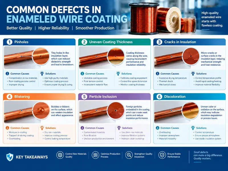
Morphological defects: pinholes, blistering, and uneven thickness
Pinholes
Pinholes are the most common and dangerous defects on enamel coatings. They appear as tiny holes (typically less than 50 μm in diameter) in the enamel coating, difficult to detect with the naked eye but clearly visible under a microscope. The conductor at the pinhole is directly exposed to air, and breakdown will occur once a voltage is applied.
The main causes of pinholes include: paint contamination (dust, metal shavings, gel particles produced by paint aging), excessively high ambient humidity (>70% RH allowing moisture to mix into the enamel coating), insufficient baking temperature (<200°C or too short a time causing incomplete solvent evaporation), and residues on the conductor surface (drawing oil, sweat stains, polishing paste not cleaned properly before painting). Pinholes directly reduce breakdown voltage (by 30%-70% for the same thickness), reduce insulation resistance, and shorten the electrical life of the motor/transformer. GB/T 6109 and IEC 60851-5 specify the allowable number of pinholes per 30 m of enamel wire (Grade 1 ≤ 5 / Grade 2 ≤ 3 / Grade 3 ≤ 1). Solution: Filter the paint liquid (10-50 μm filter), control the ambient humidity (≤60% RH), increase the baking temperature (5-10°C), and strengthen the cleaning of the conductor surface (acid pickling-water washing-passivation-drying 4-step method).
Blister (Blister / Bubbles)
Bubbling is a phenomenon of localized protrusions on the surface of the enamel coating, ranging in diameter from tens of micrometers to several millimeters. It is divided into primary bubbling caused during the painting process and secondary bubbling caused during baking/use. Primary bubbling is mainly caused by insufficient solvent evaporation: if the preheating zone temperature is too low (<100°C) or the linear velocity is too high (>500 m/min), the solvent evaporates rapidly, forming bubbles that are trapped within the enamel coating. When the paint viscosity is too low (<50 seconds/4# cup), the leveling properties are poor, making it difficult for bubbles to escape. Secondary bubbling is mostly related to the substrate or process: residual micropores, oil, and polishing paste on the conductor surface expand when heated after painting, forming bubbles at the interface between the conductor and the enamel coating. The thickness of the enamel coating at the bubbling area becomes drastically thinner (only 20%-50% of the normal area), and the breakdown voltage drops significantly.
GB/T 6109 stipulates that visible bubbles are not allowed on the surface of enamel coating. Solutions: Increase the preheating zone temperature (20-30°C), reduce the linear speed (10-15%), adjust the paint viscosity to 70-90 seconds/4# cup, and strengthen the conductor pretreatment.
Uneven enamel coating thickness (Coating Thickness Variation)
Uneven enamel coating thickness manifests as wire diameter fluctuations (outer diameter deviation exceeding ±10%) and poor concentricity (significant thickness differences in different orientations), which are key indicators for measuring enamel coating uniformity. Wear of the coating mold (mold inner diameter deviation >5% after >500 hours of use) or uncleanliness are the primary causes. Fluctuations in paint temperature (±5°C) lead to viscosity changes. Fluctuations in linear velocity (±2% or more) affect the residence time of the paint on the conductor. Vibration of the guide roller and conductor eccentricity can also cause enamel coating eccentricity. Thinner areas result in lower breakdown voltage, while thicker areas increase coil volume (reducing slot fill factor). GB/T 6109 and IEC 60851-2 specify an outer diameter deviation ≤ ±10% (Grade 1/2) or ±8% (Grade 3).
Solution: Replace the coating mold regularly (every 200-500 hours), stabilize the paint temperature (±2°C), stabilize the linear speed (±2%), and use guide rollers and straightening devices to eliminate conductor vibration and bending.
Mechanical Defects: Cracks and Peeling
Cracks
Cracks are the initiation of enamel coatings under mechanical or thermal stress. They can be classified into microcracks (invisible to the naked eye, requiring a 10-50x magnifying glass) and macrocracks (visible to the naked eye). Mechanical stress is the primary cause: excessively small bending radii (<3 times the wire diameter), excessively large bending angles (>90°), and excessively rapid stretching (>100 mm/min). Excessively thick (>50 μm) or thin (<10 μm) enamel coatings increase the risk of cracking. Poor flexibility of the enamel coating itself (e.g., polyimide enamel coatings at low temperatures) is also a contributing factor. Thermal stress is equally important: the significant difference in thermal expansion coefficients between the enamel coating and the copper conductor leads to shrinkage stress during cooling after baking; temperature cycling during storage or use (-40°C to 180°C) can cause fatigue cracking of the enamel coating.
Cracks are a direct pathway for insulation failure—moisture, impurities, and ions penetrate through cracks, causing a sharp drop in insulation resistance and a breakdown voltage of 0. GB/T 6109 stipulates that no visible cracks are allowed in the enamel coating after a thermal shock test (130-220°C × 1h). Testing methods: IEC 60851-6 thermal shock test (mandrel winding + heating), IEC 60851-3 bending test, IEC 60851-3 rapid tensile test (snap test, winding speed <1 second). Solutions: Control the enamel coating thickness within the standard range (Grade 1/2/3 corresponds to 10-30/20-50/30-80 μm); select an enamel coating system with better flexibility (such as a polyester imide + polyamide-imide composite coating); optimize the winding process (minimum bending radius 3 times wire diameter, tension ≤ 5 N); eliminate internal stress (using preheating or annealing treatment).
Enamel Coating Stripping (Coating Delamination)
Peeling is the loss of adhesion between the enamel coating and the conductor, manifested as the enamel coating delaminating, lifting, and detaching from the conductor surface. Conductor surface contamination (drawing oil, sweat stains, acid and alkali residues) is the primary cause—contaminants form a “layer” between the enamel coating and the conductor, reducing adhesion by more than 50%. Excessively high conductor surface roughness (Ra > 1.6 μm) creates stress concentration points, further reducing adhesion. Improper paint formulation (insufficient polar groups, incorrect curing agent selection) can also lead to poor adhesion. Excessively high baking temperatures (> 400°C) can cause the enamel coating to over-cur and become brittle, further reducing adhesion.
The stripped area is highly susceptible to damage during winding, embedding, and shaping, directly exposing the conductor and causing a short circuit. GB/T 6109 specifies a peel force ≥ standard value (e.g., ≥ 4.5 N / Grade 1 for 1.0 mm copper wire). Testing methods: IEC 60851-3 peel test, wrap test, and snap test. Optimal conductor surface roughness Ra = 0.4-0.8 μm.
Solution: Enhance conductor pretreatment (pickling-washing-passivation-drying); control conductor surface roughness (Ra 0.4-0.8 μm); optimize paint formulation (increase polar groups -OH, -COOH, -NH-); select isocyanate-containing curing agent system (to form chemical bonds with -OH on copper surface); control baking temperature within the standard curve range (avoid over-curing).
Thermal and chemical defects: charring, discoloration, and incomplete curing
Burning and Discoloration
Burning is a phenomenon that occurs when the enamel coating overheats during baking or operation, manifesting as localized or overall blackening, brittleness, and carbonization. Discoloration is a milder form, where the enamel coating turns yellow or darker, but without significant carbonization.
Excessive baking temperature (>450°C) or baking time (>15 seconds/pass) will directly scorch the enamel coating. Impurities (metal shavings, catalyst residue) mixed in the coating will form localized hot spots. Operating temperatures exceeding the thermal class of the enamel coating (lifespan halved for every 10°C increase, following Arrhenius’s law) will accelerate aging and discoloration of the enamel coating. Scorched areas will completely lose insulation performance, directly exposing the conductor. Discolored areas, while not completely failed, will show increased brittleness and decreased thermal class, indicating early failure.
Solution: Calibrate the baking temperature profile (preheating zone 100-150°C / curing zone 300-400°C / post-curing zone 200-250°C), and monitor oven temperature uniformity (±5°C). Select a thermally matched enamel coating (130°C / 155°C / 180°C / 200°C / 220°C) and maintain a temperature margin of 10-30°C. Control operating conditions (current density, heat dissipation, ambient temperature).
Uncured vs. Under-cured
Uncured enamel coating exhibits insufficient cross-linking, poor adhesion, and low electrical properties, manifesting as a soft, easily peeled coating with low breakdown voltage. Incomplete cross-linking occurs due to excessively low baking temperature (<300°C) or baking time (<5 seconds/pass). High paint viscosity or excessively thick coatings prevent adequate curing of the inner layers. Insufficient catalyst or hardener is also a common cause. Uncured enamel coatings continue to cross-link and shrink during storage or use, leading to cracking and peeling.
Solution: Calibrate the baking temperature profile to ensure sufficient preheating zone temperature (150-200°C for complete solvent evaporation) and adequate curing zone temperature (300-400°C for complete crosslinking). Control the paint viscosity and enamel coating thickness (Grade 1/2/3 corresponds to 10-30/20-50/30-80 μm). Regularly monitor paint activity (viscosity, solids content, acid value).
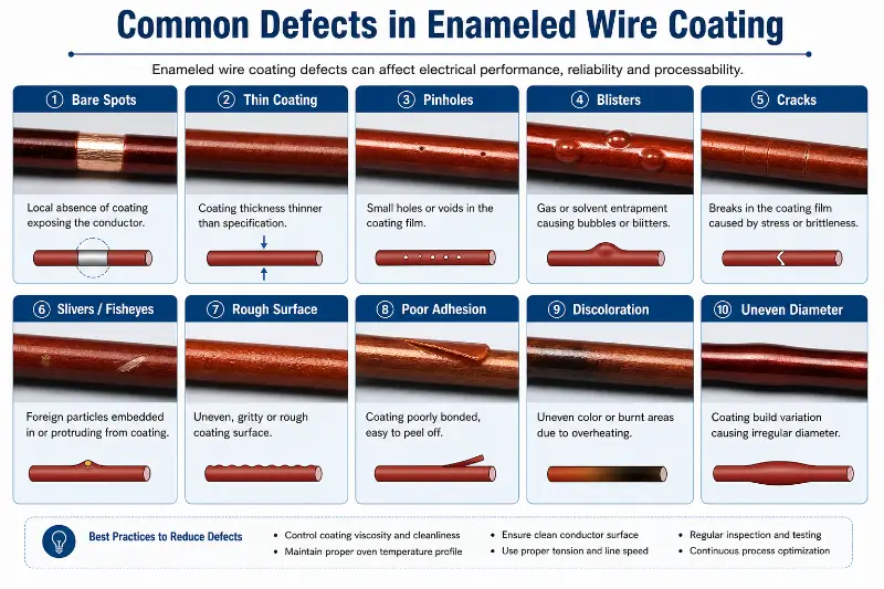
Mechanical and storage defects: scratches and moisture absorption
Scratches and Mechanical Damage
Scratches are linear damage to the enamel coating caused by external forces, which can be caused by the take-up and untake-up wires, guide rollers, dies, and metal parts of the winding equipment. Excessive take-up and untake-up tension (>10 N) will stretch the enamel coating. Burrs, sharp edges, and scratches on guide rollers, dies, and guide pins will scratch the enamel coating. Wear on the wire-passing parts of the winding equipment (>0.2 mm grooves) will continuously damage the enamel coating. During manual operation, tool collisions, stepping, and stretching will also cause damage. Scratches directly expose the conductor, resulting in complete loss of insulation performance. Scratches can also become the starting point for cracks and peeling.
Solution: Control the winding and unwinding tension (1.0 mm wire ≤ 5 N, 0.5 mm wire ≤ 2 N); regularly inspect and grind/replace guide rollers, dies, and guide pins (surface roughness Ra < 0.4 μm); use dedicated winding equipment (closed-loop tension control); strengthen operator training (avoid manual pulling and stepping).
Storage and Transportation Defects
Defects occurring during storage and transportation mainly manifest as: moisture absorption, aging, deformation, and contamination of the enamel coating. High ambient temperatures (>30°C) or direct sunlight accelerate aging. High ambient humidity (>70% RH) causes moisture absorption (especially in polyurethane enamel coatings), leading to a decrease in insulation resistance. Prolonged storage (>12 months) results in natural aging of the enamel coating. Coexistence with chemicals (acids, alkalis, solvents) will cause corrosion.
Solution: Storage conditions—temperature 5-30°C, humidity 30-70% RH, protected from light, well-ventilated, and away from chemicals. Shelf life is controlled at 6-12 months. Sealed packaging (PE film + desiccant). During transportation, use ISPM-15 standard wooden pallets + PE film + steel straps for securing and edge protection.
Comprehensive Testing System and Defect Comparison Table
Offline Detection Projects
Visual inspection (color uniformity, continuity, defect type), dimensional measurement (conductor diameter, enamel coating thickness, overall outer diameter), electrical testing (DC resistance, breakdown voltage, insulation resistance, pinholes, dielectric loss), mechanical testing (elongation, tensile strength, winding test, rapid stretching, peel force, springback angle), thermal testing (thermal shock, softening breakdown, thermal aging, temperature index), and chemical testing (solvent resistance, oil resistance, refrigerant resistance).
Online Testing Items
Continuous breakdown voltage testing (100% online), timed elongation sampling (every 2 hours), timed conductor resistance testing (per batch), continuous enamel coating thickness testing (online diameter gauge), and timed thermal shock sampling (per shift). Online testing combined with SPC (Statistical Process Control) allows for real-time monitoring of quality fluctuations.
Third-Party Certification and Standards
UL 1446 / UL 2353 (North American market, 4-8 weeks), IEC 60317 series (global market, 2-4 weeks), JIS C 3202 (Japanese market, 2-4 weeks), GB/T 6109 (Chinese market, 2-4 weeks). Core testing methods: IEC 60851-1 General, IEC 60851-2 Dimensional measurement, IEC 60851-3 Mechanical properties (flexibility + adhesion), IEC 60851-4 Chemical properties, IEC 60851-5 Electrical properties (breakdown + pinhole), IEC 60851-6 Heat resistance.
8 Major Defects: Impact-Solution Comparison Table
| Defect Type | Main Causes | Main Impacts | Key Detection Standards | Core Solutions |
|---|---|---|---|---|
| Pinhole | Paint contamination, excessive humidity, insufficient baking | Breakdown voltage drop of 30-70% | IEC 60851-5 Pinhole Test | Filtering paint, controlling humidity, increasing baking temperature |
| Bubbling | Insufficient preheating, excessive linear speed, low paint viscosity | Thin spots, peeling risk in enamel coating | Visual inspection + thickness measurement | Increase preheating zone temperature, decrease linear speed |
| Cracks | Mechanical stress, thermal stress, embrittlement of the enamel coating | Direct insulation failure | IEC 60851-6 Thermal shock | Optimize winding process, select flexible enamel coatings |
| Uneven thickness | Mold wear, paint fluctuation, linear speed fluctuation | Thin spots puncture, thick spots have low fill rate | IEC 60851-2 dimensions | Regular mold changes, stable temperature/speed |
| Peeling | Conductor contamination, improper paint formulation, over-curing | Wire breakage, poor adhesion | IEC 60851-3 Peeling/Wrapping | Enhanced pretreatment, optimized paint formulation |
| Burning | Overheating during baking, overload during operation | Complete failure of the enamel coating | Thermal aging test, breakdown voltage | Calibrate the baking profile, reduce the operating temperature |
| Scratches | Excessive tension, burrs on guide rollers, improper operation | Directly exposed insulation | 100% online breakdown | Closed-loop tension control, regular replacement of guide rollers |
| Storage Defects | Improper Temperature and Humidity, Excessive Storage Period | Moisture Absorption, Aging, Contamination | Storage Condition Inspection + Factory Re-inspection | Control 5-30°C / 30-70% RH / <12 Months |
Selection and Quality Control Decision Process
Step 1: Assess Application Scenarios
Specify the motor type (DC/AC/servo/traction/industrial/home appliance/automotive/aviation), operating temperature (hot spot temperature + margin), voltage level (low voltage <1 kV / medium voltage 1-10 kV / high voltage >10 kV), lifespan requirements (5000 / 20000 / 100000 hours), and certification requirements (UL/IEC/JIS/GB).
Step 2: Determine the enamel coating level
Select the enamel coating thickness grade (Grade 1/2/3) and thermal class (130/155/180/200/220) based on voltage level and lifespan requirements. For general motors, choose Grade 2 + 155-180°C; for high-voltage motors, choose Grade 3 + 180-200°C; for automotive drives, choose Grade 2 + 180-200°C; and for aerospace motors, choose Grade 3 + 200-220°C.
Step 3: Sampling Verification
Each batch undergoes sampling tests upon arrival at the factory: appearance, dimensions, breakdown voltage, pinholes, thermal shock, and peel force. Sample quantity ≥ 5 reels/batch. During the winding/embedding process, online 100% breakdown voltage testing, visual inspection (CCD inspection of enamel coating defects), and periodic sampling tests (elongation every 2 hours, thermal shock per shift) are conducted.
Step 4: Failure Analysis
When failures occur, troubleshoot according to the eight major defect types: observe appearance (pinholes/blistering/cracks/scratches/discoloration) → measure dimensions (thickness/concentricity) → test electrical properties (breakdown/insulation resistance) → perform microscopic analysis (enamel coating cross-section/interface) → identify root causes (materials/processes/storage/operations). Establish an SPC statistical process control chart (pinhole count/breakdown voltage/thermal shock pass rate), set control limits (±3σ), and issue warnings for exceeding limits. Establish supplier quality files (reviewed quarterly) to trace paint batches, conductor batches, and process parameters.
Summary
Core Conclusions
The root cause of defects in enamel coatings lies in their “ultra-thin precision coating” nature—a thickness of 10-50 μm must fulfill multiple functions including insulation, mechanical, thermal, and chemical properties, while maintaining uniformity and integrity during high-speed coating processes at speeds of hundreds of meters per minute. This article systematically reviews eight major defect types (pinholes, blistering, cracks, uneven thickness, peeling, scorching, scratches, and storage defects) covering the entire lifecycle from manufacturing to use.
Three-tiered prevention system
From a materials system perspective, selecting paints with good flexibility, strong adhesion, and matching thermal class (such as polyester imide + polyamide-imide composite coatings) is the first line of defense against defects. The surface condition of the conductor (Ra 0.4-0.8 μm, clean and uncontaminated) is fundamental to the adhesion of the enamel coating. From a process perspective, stabilizing the baking curve (preheating/curing/post-curing stages), paint temperature (±2°C), linear velocity (±2%), and tension (closed-loop control) are key windows for controlling defects. From a quality control perspective, establishing a comprehensive process system of “incoming sampling + 100% online inspection + failure tracing + SPC statistics,” coupled with supplier quality records and third-party certifications (UL/IEC/JIS/GB), can significantly reduce the defect rate.
Engineering Practice Recommendations
Engineering practice shows that the cost of preventing defects in enameled wire and enamel coating is far lower than the cost of repairing them after failure—a single motor winding failure due to pinholes can render the entire motor unusable, while a comprehensive solution combining a 10-50 μm filter, humidity control, and optimized baking profile can reduce the pinhole rate by more than 80%. It is recommended that users clearly specify the enamel coating grade, testing methods, acceptance criteria (AQL), and failure traceability mechanism in their enameled wire procurement technical agreements, and establish a long-term collaborative quality improvement mechanism with suppliers. For the first small batch supply (within 500 kg) from new suppliers, it is recommended to tighten the sampling ratio (sample quantity ≥ 10 reels/batch) and require complete traceability documentation for the paint batch, conductor batch, and process parameters.