

Introduction and Engineering Background
The Status of Glass Fiber Covered Wire in the Electrical Industry
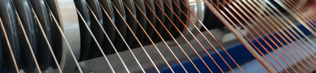
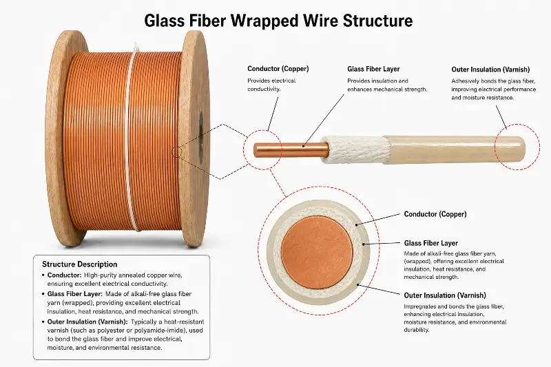
Glass fiber covered wire (also known as glass-fiber covered magnet wire) is a composite insulated wire made by spirally wrapping alkali-free glass fiber yarn (E-Glass Fiber Yarn, according to ASTM D578 / IEC 60317-0-6) around the surface of enameled copper or aluminum wire, and then impregnating and curing it with silicone varnish/epoxy resin/polyester resin. It is the third largest type of winding conductor after enameled wire and paper-insulated wire. Its core advantages lie in the high heat resistance (up to Class C 220°C long-term operating temperature + short-term 350°C impact resistance), high dielectric strength (typical breakdown voltage range of 1.5 kV to 6.0 kV rms), and high mechanical strength (wear-resistant, scratch-resistant, and vibration-resistant) imparted by inorganic glass fibers, making it an irreplaceable winding material for high-voltage, high-temperature, high-vibration, and high-reliability applications.
Engineering Significance of Single-Layer and Double-Layer Structures
In the glass fiber insulated wire industry chain, the “number of insulation layers” is one of the core dimensions that distinguishes product specifications from application grades: Single-layer glass fiber insulated wire (Single-Layer / Grade G1 single-layer) has a single layer of glass fiber yarn wrapped around the surface of the enameled conductor in a single direction (clockwise or counterclockwise). The total thickness of the insulation layer ranges from 0.10 mm to 0.20 mm. It is mainly used for Class B 130°C / Class F 155°C medium and low voltage small and medium-sized motors, household appliances, and low voltage transformer windings. Double-layer glass fiber insulated wire (Double-Layer / Grade G2 double-insulated) involves wrapping two layers of glass fiber yarn in opposite directions twice on the surface of the enameled conductor (the first layer is clockwise, and the second layer is counterclockwise, or vice versa). The total insulation layer thickness ranges from 0.20 mm to 0.40 mm. It is mainly designed for high-reliability, long-life applications such as Class H 180°C / Class C 220°C and above high-voltage motors, wind power generation, rail traction motors, HVDC converters, and nuclear power main pump motors. Increasing the number of insulated layers from one to two is not simply a matter of “doubling the thickness,” but rather a leap in engineering performance across dielectric, mechanical, and thermal dimensions: the reverse wrapping process of the second layer of glass fiber yarn allows the insulation layer to maintain a more stable geometry under bending stress, while significantly improving key reliability indicators such as breakdown voltage, thermal life, mechanical vibration resistance, and chemical resistance.
Comparison with Existing Research
Most existing literature on glass fiber-insulated wire discusses the advantages of glass fiber-insulated wire from a single dimension (such as thermal rating, mechanical strength, or breakdown voltage), but lacks a systematic comparison between single-layer and double-layer glass fiber-insulated wires. This paper uses the three major standard systems of IEC 60317-0-6 / NEMA MW 1000 / GB/T 7672 as the underlying specifications, systematically compares the key differences between single-layer and double-layer glass fiber-insulated wires from sixteen engineering dimensions, and establishes a five-step selection decision framework.
Conductor and Glass Fiber Fundamentals
Conductor Materials and Specifications
The conductors of glass fiber-insulated wires can be oxygen-free copper (OFC / C10100 / C10200 OFHC), electrical round copper wire (C11000 ETP containing 0.02-0.04% Cu₂O), or electrical round aluminum wire (1350-O / 6101-T6), manufactured according to the preferred number series of IEC 60028 R20. The round wire specifications cover 0.500 mm to 6.000 mm (typically 0.511 mm to 4.115 mm for AWG 24 to AWG 6), and the flat wire specifications cover 0.800 mm to 5.600 mm in thickness and 2.000 mm to 16.000 mm in width (typical cross-sectional area 1.6 mm² to 89.6 mm²). The conductor surface must be pre-coated with a primer (PEW/PEI/UEW) to enhance adhesion to the fiberglass yarn.
Glass Fiber Type and Treatment
The alkali-free glass fiber yarn (E-Glass Yarn) used for glass fiber wrapping is specified as alkali-free borosilicate glass (Al₂O₃ < 0.8%, CaO < 0.8%, SiO₂ > 52%) according to ASTM D578 / IEC 60317-0-6, with a fiber diameter of 6 µm to 9 µm and a single filament tensile strength of 3.0 GPa to 4.5 GPa. Before use, the glass yarn needs to be surface-treated with a silane coupling agent (such as KH-550 / KH-560) to enhance its chemical compatibility with silicone varnish, and then impregnated and cured with silicone varnish (typical grades W61-901 / W61-903, heat resistant above 200°C). Fiber twist is typically 20 to 60 TPM (Turns Per Meter). High-twist fiber yarns can significantly improve the mechanical strength of single-layer structures.
Engineering Characteristics of Single-Layer Glass Wire Wrapped Wire
###
Structure and Manufacturing Process
The manufacturing process of single-layer glass wire wrapped wire includes four main steps: preheating (80°C to 120°C to remove surface moisture), glass wire wrapping (wrapping angle 50° to 70°, wrapping pitch 4 mm to 12 mm, tension 1.5 N to 5.0 N), silicone varnish impregnation (viscosity 30 s to 60 s, 4 cups/25°C), and vertical or horizontal oven curing (gradual temperature rise 200°C to 280°C, curing time 8 h to 16 h). The wrapping pitch (Lay Length / Pitch) is a key process parameter for single-layer structures: too short a pitch leads to fiber cross-over and uneven thickness; too long a pitch leads to incomplete coverage and a decrease in breakdown voltage.
###
Key Performance Indicators
Typical performance range for single-layer glass fiber insulated wire: Total insulation layer thickness 0.10 mm to 0.20 mm; Breakdown voltage 1.5 kV to 3.0 kV rms (tested according to IEC 60851-3 metal round bar method or twisted pair method); Thermal class Class B 130°C / Class F 155°C; Tensile strength comparable to bare enameled wire (10A annealed state ≥110 MPa / 15A annealed state ≥130 MPa); Elongation ≥30% (tested according to IEC 60851-3); Springback angle ≤5° (tested according to NEMA MW 1000); Flexibility allows for 180° bending without cracking on a 5× diameter round bar; Adhesion scratch test ≥30 times (according to IEC 60851-3 §5.3); Impregnating varnish absorption rate 8% Up to 15% (tested according to ASTM D202).
###
Advantages and Limitations
Core advantages of single-layer structures: lower cost (materials and labor are 50% to 65% of double-layer structures); smaller outer diameter and higher winding slot fill factor (round wire 0.45 to 0.55 slot fill factor / flat wire 0.65 to 0.78 slot fill factor); better flexibility and simpler winding process; suitable for automated high-speed winding (10 m/min to 80 m/min). Core limitations of single-layer structures: lower breakdown voltage (1.5 kV to 3.0 kV rms, limiting high-voltage applications); limited thermal class (typically Class B / Class F, not suitable for Class H and above); shorter thermal life (20,000 h @ 155°C, extrapolated from the Arrhenius model); weaker mechanical vibration tolerance (prone to fiber wear and delamination under high vibration conditions).
Engineering Characteristics of Double-Layer Glass Fiber Insulated Wire
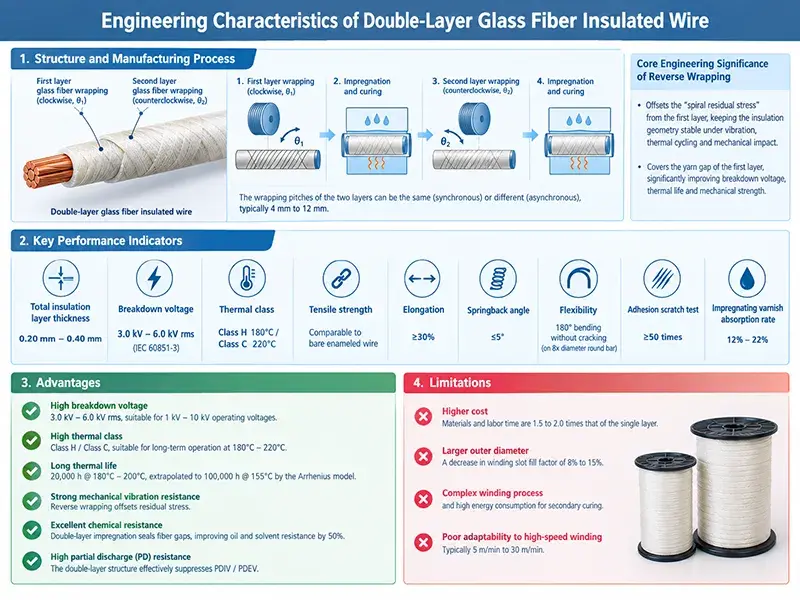
Structure and Manufacturing Process Double-layer glass fiber insulated wire adds a “second layer reverse wrapping + secondary impregnation and curing” process to the single-layer process. The first layer of glass yarn is wrapped clockwise at a wrapping angle θ₁ and then impregnated and cured. The second layer is wrapped counterclockwise in the opposite direction (the wrapping angle θ₂ and θ₁ are 90° to 180°, typically 180° completely opposite) and then impregnated and cured a second time. The wrapping pitches of the two layers can be the same (synchronous wrapping) or different (asynchronous wrapping), typically 4 mm to 12 mm. The core engineering significance of reverse wrapping: The second reverse wrapping can offset the “spiral residual stress” generated by the first wrapping, allowing the insulation layer to maintain a more stable geometry under medium- and high-frequency vibration, thermal cycling, and mechanical impact; at the same time, the second layer covers the yarn gap of the first layer, significantly improving breakdown voltage, thermal life, and mechanical strength. Key Performance Indicators Typical performance range of double-layer glass fiber wrapped wire: Total insulation layer thickness 0.20 mm to 0.40 mm; Breakdown voltage 3.0 kV to 6.0 kV rms (tested according to IEC 60851-3); Thermal class Class H 180°C / Class C 220°C; Tensile strength comparable to bare enameled wire; Elongation ≥30%; Springback angle ≤5°; Flexibility allows for 180° bending without cracking on an 8× diameter round bar; Adhesion scratch test ≥50 times; Impregnating varnish absorption rate 12% to 22%. Advantages and Limitations The core advantages of the double-layer structure are: high breakdown voltage (3.0 kV to 6.0 kV rms, suitable for 1 kV to 10 kV operating voltages); high thermal class (Class H / Class C, suitable for long-term operation at 180°C to 220°C); long thermal life (20,000 h @ 180°C to 200°C, extrapolated to 100,000 h @ 155°C by the Arrhenius model); strong mechanical vibration resistance (reverse wrapping offsets residual stress); excellent chemical resistance (double-layer impregnation seals fiber gaps, improving oil and solvent resistance by 50%); and high partial discharge (PD) resistance (the double-layer structure effectively suppresses PDIV / PDEV). The core limitations of the double-layer structure are: higher cost (materials and labor time are 1.5 to 2.0 times that of the single layer); larger outer diameter and a decrease in winding slot fill factor of 8% to 15%; complex winding process and high energy consumption for secondary curing; and poor adaptability to high-speed winding (typically 5 m/min to 30 m/min).
Single-Layer vs. Double-Layer Core Difference Comparison Matrix
Sixteen-Dimensional Engineering Comparison
The table below systematically compares the key differences between single-layer and double-layer glass fiber insulation across sixteen engineering dimensions:
| Dimension | Single-Layer | Double-Layer | Difference Description |
|---|---|---|---|
| Insulation Layer Thickness (mm) | 0.10–0.20 | 0.20–0.40 | Double-layer doubles |
| Breakdown Voltage (kV rms) | 1.5–3.0 | 3.0–6.0 | Double-layer 2.0× to 2.5× |
| Thermal Class | Class B/F (130°C / 155°C) | Class H/C (180°C / 220°C) | Two levels higher |
| Thermal Life (h @ 155°C) | 20,000 | 50,000–100,000 | Double-layer 2.5×–5.0× |
| Tensile Strength (MPa) | Same as enameled wire | Same as enameled wire | Same |
| Elongation (%) | ≥30 | ≥30 | Same |
| Springback Angle (°) | ≤5 | ≤5 | Same |
| Flexibility (Bending Diameter) | 5× Wire Diameter | 8× Wire Diameter | Double-layer downgrade |
| Adhesion (Scraping Times) | ≥30 | ≥50 | Double-layer +67% |
| Impregnating Varnish Absorption Rate (%) | 8–15 | 12–22 | Double-layer +50% |
| Slot Fill Factor Effect | Baseline | Downgrade 8%–15% | Double-layer downgrade |
| Winding Speed (m/min) | 10–80 | 5–30 | Double-layer downgrade 50% |
| Relative Cost Multiple | 1.0× | 1.5×–2.0× | Double-layer higher |
| Mechanical Vibration Resistance | Benchmark | Improved by 30%–50% | Double-layer superior |
| Partial Discharge (PDIV) | Benchmark | Improved by 50%–100% | Double-layer superior |
| Chemical Resistance | Benchmark | Improved by 30%–50% | Double-layer superior |
Breakdown voltage and electric field distribution
The advantage of the double-layer structure in terms of breakdown voltage stems from the “double-layer series capacitor” model: two layers of glass fiber impregnated dielectric bear the applied voltage in series, with each layer sharing approximately half of the electric field strength; at the same time, the reverse wrapping ensures that the gap between the second layer of fibers is staggered from that of the first layer (the misalignment coverage rate reaches more than 80%), effectively suppressing surface discharge. The breakdown voltage of the double-layer structure is typically 2.0 to 2.5 times that of the single-layer structure, conforming to the nonlinear superposition law under the IEC 60851-3 test method.
Thermal Life and Arrhenius Model
The thermal life of single-layer and double-layer glass fiber-wrapped yarns was tested according to ASTM D2307: Single-layer Class F 155°C 20,000 h; Double-layer Class H 180°C 20,000 h (2.5 to 5.0 times longer thermal life than single-layer under the same thermal class); Double-layer Class C 220°C 10,000 h (extrapolated according to IEC 60172). In the Arrhenius model log10 L = A + B/T, the A value (material constant) of the double-layer structure is significantly higher than that of the single-layer structure, reflecting the synergistic aging resistance advantage of the double-layer impregnation varnish and glass fiber.
Mechanical Strength and Flexibility
Single-layer structures, lacking a second layer of constraint within the wrapping pitch, are prone to fiber slippage and delamination under bending stress. Double-layer reverse wrapping, however, significantly improves bending resistance through geometric interlocking. But with double-layer structures, the total thickness doubles, reducing the flexibility index (minimum bending diameter) from 5 × wire diameter to 8 × wire diameter.
International Standards and Quality Verification
IEC Standards System
IEC 60317-0-6:2020 General requirements for glass fiber wrapped insulated round copper wire (applicable to single and double-layer structures); IEC 60317-0-7:2020 General requirements for glass fiber wrapped insulated flat copper wire; IEC 60317-31 / 32 / 33 / 34 / 35 / 36 Standards for various glass fiber wrapped wire products (different thermal classes); IEC 60851-1~6 Test methods for winding wires (breakdown voltage, elongation, springback angle, adhesion, scratching, thermal shock).
NEMA Standards
NEMA MW 1000-2023 Part 2 Magnet Wire (Fiberglass Covered, Round); NEMA MW 1000-2023 Part 3 Rectangular Copper/Aluminum Wire (Fiberglass Covered, Round).
Chinese National Standards
GB/T 7672.1-2008 Magnet Wire (Fiberglass Covered, Round); GB/T 7672.2-2008 Rectangular Copper Wire (Fiberglass Covered); GB/T 7672.3-2008 Rectangular Aluminum Wire (Fiberglass Covered); GB/T 7672.4-2008 Rectangular Aluminum Wire (Fiberglass Covered); GB/T 4074.1~6 Test Methods for Winding Wires.
Quality Verification and Sampling
Sampling inspection according to ISO 2859-1 AQL 1.0 Level II: Breakdown voltage: single layer ≥1.5 kV / double layer ≥3.0 kV; Adhesion: single layer ≥30 times / double layer ≥50 times; Thermal shock resistance: single layer 155°C / double layer 180°C for 30 minutes without cracking; Dimensional tolerance: round wire ±0.013 mm / flat wire ±0.020 mm.
Typical Application Scenarios Comparison
Typical applications of single-layer structure: small motors (household appliance motors, power tool motors, Class B/F 130/155°C); low-voltage transformers (control transformers, signal transformers, ≤1 kV); automotive motors (starter motors, generator auxiliary windings); lighting appliances (fluorescent lamp ballasts, LED driver transformers). Typical applications of double-layer structure: high-voltage motors (3 kV to 10 kV high-voltage asynchronous motors, synchronous motors); wind power generation (doubly fed asynchronous generator DFIG, direct-drive permanent magnet synchronous generator PMSG-DD, Class H/C); rail transit (CRH train traction motor, metro traction transformer, IEC 61373 Cat 1 Class B vibration); HVDC converter transformer (±500 kV to ±800 kV converter transformer valve side winding); nuclear power main pump motor (Class H 180°C, 60-year lifespan).
Five-Step Selection Decision-Making Framework
In the operating voltage determination stage, single-layer is selected for ≤1 kV, and double-layer for 1 kV to 10 kV; in the thermal rating matching stage, single-layer is selected for Class B/F, and double-layer for Class H/C; in the lifespan requirement stage, single-layer is selected for ≤20 years, and double-layer for 20 to 30 years; in the vibration environment stage, single-layer is selected for low vibration, and double-layer is selected for high vibration (rail transit, wind power, nuclear power); in the economic evaluation stage, single-layer is selected for cost-sensitive applications, and double-layer is selected for reliability-priority applications.
Conclusion
The difference between single-layer and double-layer glass fiber sheathing is not simply a matter of “thickness difference,” but rather a differentiated design for different engineering application scenarios. Single-layer structures, with their core advantages of “low cost + small outer diameter + high slot fill factor,” dominate the Class B/F low-voltage small and medium-sized motor and home appliance market; double-layer structures, with their core advantages of “high breakdown voltage + high heat resistance + high reliability,” dominate the Class H/C high-voltage, high-reliability, long-life application scenarios. The essence of selection decisions is an engineering balance between “performance vs. cost”: single-layer wires are preferred for scenarios with operating voltage ≤1 kV, thermal rating Class B/F, and a lifespan requirement of 10 to 20 years; double-layer wires are necessary for scenarios with operating voltage 1 kV to 10 kV, thermal rating Class H/C, a lifespan requirement of 20 to 30 years, and harsh vibration environments. In the future, with the continued growth of high-voltage, high-reliability applications such as wind power, rail transportation, HVDC, and new energy vehicles, the market share of double-layer glass fiber-insulated wires will continue to expand; meanwhile, single-layer structures will maintain stable demand in cost-sensitive markets such as home appliances and power tools.