


Introduction
The choice of insulation thickness for paper-insulated wire is essentially a four-dimensional engineering decision involving voltage level, insulation material, manufacturing process, and economics. It is not simply a matter of “the thicker the better,” nor is it a simple trade-off of the latter being cheaper. For every 0.05 mm increase in insulation paper thickness, the effective conductive cross-section per ton of conductor decreases by 1.5–2.0%, window utilization decreases by 4–6%, and the temperature rise increases by an additional 2–3 K. On the other hand, for every 0.05 mm decrease in thickness, the power frequency withstand voltage margin of a 110 kV power transformer may shrink from 30% to 12%, and the partial discharge initiation voltage may drop from 1.5 Uₙ to 1.1 Uₙ, leading to an exponential increase in the risk of breakdown during long-term operation. From an engineering practice perspective in the transformer manufacturing industry, paper-covered wire (PCW) is a core insulation form for windings in oil-immersed power transformers, dry-type transformers, high-voltage motors, traction transformers, rectifier transformers, and electric furnace transformers. The choice of its insulation thickness directly affects the dielectric strength, heat dissipation capacity, short-circuit mechanical strength, long-term operational reliability, and life-cycle cost of the equipment. Understanding the composition of paper-covered wire insulation thickness, the differences in insulating paper types and single-layer thicknesses, enamel coating thickness matching, the total insulation thickness selection matrix, application-driven selection, wrapping process constraints, breakdown voltage and electric field distribution, thermal performance and heat dissipation balance, international standards systems, and quality verification methods is of significant practical guiding importance for transformer design engineers, motor design engineers, procurement quality engineers, and technical decision-makers. The engineering implications of paper-covered wire insulation thickness selection can be systematically explained from twelve dimensions: the basic composition of paper-covered wire insulation thickness, insulation paper type and single-layer thickness, enamel coating thickness matching, total insulation thickness selection matrix, application scenario-driven selection, wrapping process constraints, breakdown voltage and electric field distribution, thermal performance and heat dissipation balance, international standard system, quality verification and testing methods, selection decision framework, and typical case analysis. This article provides a systematic engineering reference for transformer manufacturers, oil-immersed transformer design engineers, dry-type transformer design engineers, high-voltage motor design engineers, traction transformer manufacturers, power transformer procurement engineers, and technical decision-makers.
Fundamental Composition of Paper Covered Wire Insulation Thickness
Thickness Structure Overview
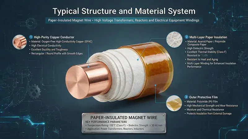
The insulation thickness of paper-insulated wire is not a single value, but a composite system consisting of conductor diameter/thickness → enamel coating layer → insulating paper layer → impregnating medium layer by layer. In engineering calculations, the following three core concepts must be distinguished: – Nominal conductor size: Diameter d (mm) for a circular conductor or thickness a × width b (mm) for a rectangular conductor. – Enamel coating thickness: The single-sided increase in thickness of the enamel coating (usually polyester/polyesterimide/polyamide-imide/polyimide) on the conductor surface, denoted as δᵥ. – Insulation paper thickness: The radial increase in thickness after wrapping the paper tape, denoted as δₚ (= single-layer thickness × effective number of layers, considering overlap rate). – Total insulation thickness: δ_total = 2δᵥ + 2δₚ (double-sided for round wire, four-sided for flat wire). – Finished outer diameter/outer dimensions: D = d + 2δᵥ + 2δₚ (round wire) / a’ = a + 2δᵥ + 2δₚ, b’ = b + 2δᵥ + 2δₚ (flat wire).
Physical Meaning of Thickness
Impact of Thickness on Conductor Properties:
| Thickness Variation | Effective Conductive Cross-Section | Resistance Increase | Slot Fill Rate / Window Utilization | Temperature Rise | Breakdown Voltage |
|---|---|---|---|---|---|
| +0.05 mm paper | Decrease 1.5–2.0% | +1.5–2.0% | Decrease 4–6% | +2–3 K | +2–4 kV |
| +0.10 mm paper | Decrease 3.0–4.0% | +3.0–4.0% | Decrease 8–12% | +4–6 K | +5–8 kV |
| +0.20 mm paper | Decrease 6.0–8.0% | +6.0–8.0% | Decrease 15–22% | +8–12 K | +12–18 kV |
Key Insight: Increasing insulation thickness has non-linear diminishing returns—the first 0.1 mm gains about 50–60% breakdown voltage improvement, while the next 0.1 mm only gains 30–40%, saturating after 0.5 mm (due to uneven electric field distribution causing the outer layer to break down first)..
Engineering Measurement of Thickness
In international standards such as IEC 60851-2, NEMA MW 1000, and GB/T 4074.2, the following methods are used to measure insulation thickness: – Build-up Method: Measure the outer diameter of the finished product, subtract the diameter of the bare conductor, and then divide by 2 to obtain the insulation thickness on one side. This method is suitable for round wires. – Rectangular Method: Measure the increase in thickness in both directions a and b. This method is suitable for flat wires. – Weight Method: Calculate the thickness (grammage/density) from the weight of the paper tape. This method is suitable for quality control. – Microscope Method: Measure directly on the cross-section of the insulating paper (arbitration method, accuracy ±0.005 mm).
Insulation Paper Types and Single-Layer Thickness
Four Major Insulation Paper Base Materials
| Insulation Paper Type | Chemical Composition | Nominal Thickness (mm) | Dielectric Strength (kV/mm) | Thermal Class | Typical Applications |
|---|---|---|---|---|---|
| Kraft Paper | Unbleached Cellulose Sulfate | 0.05 / 0.075 / 0.10 / 0.12 / 0.15 | 8–10 (Air) / 30–40 (Oil) | Class A 105°C / Class E 120°C | Distribution transformer ≤35 kV oil-immersed winding |
| Crepe Paper | Crinkled Cellulose | 0.10 / 0.13 / 0.18 / 0.25 | 6–8 (Air) / 25–35 (Oil) | Class A 105°C | Lead insulation, winding ends, bend cushioning |
| Nomex® 410 | Meta-aromatic Polyamide | 0.05 / 0.08 / 0.13 / 0.18 / 0.25 / 0.30 / 0.38 / 0.51 / 0.61 / 0.76 | 18–25 (in air) | Class H 180°C / Class N 200°C | Dry-type transformer, H-class oil-immersed transformer, wind/PV step-up |
| Nomex® 414 | Close-packed Meta-aromatic Polyamide | 0.10 / 0.18 / 0.25 / 0.38 / 0.51 / 0.76 | 30–35 (in air) | Class H 180°C / Class N 200°C | Dry-type main insulation, H-class traction motor |
| Mica Paper | Calcined Mica + Organic/Inorganic Binder | 0.05 / 0.08 / 0.10 / 0.15 / 0.20 | 25–40 (in air) | Class H 180°C / Class C 220°C+ | HV motor main insulation, fire-resistant cable, special motors |
| DMD / NMN | Polyester Film + Fiber Paper Composite | 0.10 / 0.13 / 0.15 / 0.20 / 0.25 / 0.30 | 30–50 (in air) | Class B 130°C / Class F 155°C | Dry-type transformer, HV motor slot insulation |
Core Principles of Thickness Selection
Three Principles for Selecting Single-Layer Thickness: 1. Voltage Rating Matching: ≤1 kV: 0.05–0.08 mm / 1–10 kV: 0.08–0.12 mm / 10–35 kV: 0.12–0.18 mm / 35–110 kV: 0.18–0.25 mm / ≥110 kV: 0.25–0.51 mm (Multi-layer combination) 2. Process Operability: High-speed winding machines (≥1500 RPM) are suitable for 0.05–0.08 mm thin paper; slow hand winding can use 0.18–0.25 mm thick paper. 3. Cost-Economy: Kraft Paper costs approximately 1/10–1/15 of Nomex 410, but has a thermal class 80–100°C lower temperature.
Thickness Differences Between Oil-Immersed and Dry-Type Environments
Oil-Immersed Environment (Oil-Paper Synergistic Insulation): – Dielectric strength ≈ 30–40 kV/mm (after full oil immersion) – Single-layer 0.10–0.12 mm Kraft Paper achieves 3–4 kV/layer in 110 kV oil immersion (transformer) – Total thickness can be relatively reduced (30–50% thinner than dry-type at the same voltage level) – Impregnation medium (mineral oil/synthetic ester/natural ester) has a significant impact on thickness selection. Dry-Type Environment (Air-Paper Composite Insulation): – Dielectric strength ≈ 8–10 kV/mm (in air) / 15–25 kV/mm (Nomex 410) – At the same voltage level, dry-type is 30–50% thicker than oil-immersed (e.g., 10 kV dry-type requires 0.4–0.6 mm, while oil immersion only requires 0.2–0.3 mm) – VPI vacuum pressure impregnation process can fill the gaps between paper layers, increasing dielectric strength by 10–20%. —
Enameled Coating Thickness Coordination with Insulation Class
Enameled Coating Thickness Grades
Standards such as IEC 60851-2, NEMA MW 1000, and GB/T 6109.1 classify enamel coating thickness into three levels:
| Grade | Round Wire Enamel One-Side Increment (mm) | Flat Wire Enamel One-Side Increment (mm) | Breakdown Voltage (kV rms) | Breakdown Voltage (Round Wire 0.5 mm Reference) |
|---|---|---|---|---|
| Grade 1 / G1 | 0.015–0.030 | 0.020–0.040 | 1.5–2.5 | Round wire 0.5 mm diameter ≥1.5 kV |
| Grade 2 / G2 | 0.030–0.050 | 0.040–0.070 | 2.5–4.0 | Round wire 0.5 mm diameter ≥2.5 kV |
| Grade 2 / G2 | 0.030–0.050 | 0.040–0.070 | 2.5–4.0 | Round wire 0.5 mm diameter ≥2.5 kV |
| Grade 3 / G3 | 0.050–0.080 | 0.070–0.110 | 4.0–6.0 | Round wire 0.5 mm diameter ≥5.0 kV |
Coordination Between Thermal Class and Paper Substrate
The thermal class of the enamel coating (Class B 130°C / F 155°C / H 180°C / N 200°C / R 220°C / 250°C) must match that of the insulating paper; otherwise, the “weakest link” effect will occur—the material with the lower thermal class will age first, causing the entire insulation system to fail. Typical Coating Options: | Enamel Coating Type | Temperature Resistance | Compatible Insulation Paper | Total Thermal Class | Application Scenario |
| Enamel Type | Thermal Class | Compatible Paper Insulation | Paper System Class | Typical Application |
|---|---|---|---|---|
| Polyester (PEW) | Class F 155°C | Kraft Paper + Mineral Oil | Class A 105°C | Power distribution transformer |
| Polyurethane (UEW) | Class B 130°C | Kraft Paper + Mineral Oil | Class A 105°C | Small transformer |
| Polyesterimide (PEI) | Class H 180°C | Nomex 410 + Mineral Oil | Class H 180°C | Dry-type transformer |
| Polyamide-imide (PAI) | Class N 200°C | Nomex 410 + Mineral Oil | Class N 200°C | Traction transformer, wind power |
| Polyimide (PI) | Class R 220°C / 250°C | Mica Paper + Silicone Oil | Class R 220°C | High-temperature motors, aviation |
Thickness Differences Between Single-Coat and Dual-Coat Systems
- Single Coating: Only one layer of enamel coating, thickness 0.015–0.080 mm, dielectric strength 1.5–6 kV. – Double Coating: Primer + Topcoat (e.g., PEI + PAI), thickness 0.050–0.110 mm, dielectric strength increased by 30–50% (for the same thickness grade). – Triple Coating and Above: Special applications (e.g., PI + PAI + PI), thickness 0.10–0.15 mm, dielectric strength up to 8–12 kV. Thickness Matching Recommendations: – Distribution ≤1 kV: Grade 1 enamel coating + 0.05–0.08 mm Kraft (single-layer paper) – Distribution 1–10 kV: Grade 2 enamel coating + 0.10–0.13 mm Kraft (single/double layer) – Medium voltage 10–35 kV: Grade 2/3 enamel coating + 0.13–0.18 mm Kraft (single/double layer) mm Kraft double layer or Nomex 410 single layer – High voltage 35–110 kV: Grade 3 enamel coating + 0.18–0.25 mm multilayer Kraft or Nomex 410 – Ultra-high voltage ≥110 kV: Grade 3 enamel coating + 0.25–0.51 mm multilayer Nomex 410/414 or DMD/NMN —
Total Insulation Thickness Selection Matrix
Thickness Baseline by Voltage Class
| Voltage Rating | Oil-Immersed Transformer Total Insulation (mm) | Dry-Type Transformer Total Insulation (mm) | HV Motor Total Insulation (mm) | Recommended Enamel Grade | Recommended Paper Type |
|---|---|---|---|---|---|
| ≤1 kV | 0.10–0.20 | 0.15–0.30 | 0.20–0.40 | G1 | Kraft 0.05–0.08 mm |
| 1–10 kV | 0.20–0.40 | 0.30–0.60 | 0.40–0.80 | G2 | Kraft 0.10–0.13 mm |
| 10–35 kV | 0.40–0.80 | 0.60–1.20 | 0.80–1.50 | G2–G3 | Kraft Double-Layer / Nomex 410 0.13–0.18 mm |
| 35–110 kV | 0.80–1.50 | 1.20–2.50 | 1.50–3.00 | G3 | Nomex 410/414 Multi-layer 0.18–0.51 mm |
| 110–500 kV | 1.50–3.00 | 2.50–5.00 | — | G3 + Double Coat | Nomex 414 / DMD/NMN Multi-layer |
| ≥500 kV UHV | 3.00–6.00 | — | — | G3 + Double Coat | Nomex 414 Multi-layer + Oil Duct |
Thickness Adjustment by Conductor Size
| ≤1 kV | 0.10–0.20 | 0.15–0.30 | 0.20–0.40 | G1 | Kraft 0.05–0.08 mm |
| 1–10 kV | 0.20–0.40 | 0.30–0.60 | 0.40–0.80 | G2 | Kraft 0.10–0.13 mm |
| 10–35 kV | 0.40–0.80 | 0.60–1.20 | 0.80–1.50 | G2–G3 | Kraft Double-Layer / Nomex 410 0.13–0.18 mm |
| 35–110 kV | 0.80–1.50 | 1.20–2.50 | 1.50–3.00 | G3 | Nomex 410/414 Multi-layer 0.18–0.51 mm |
| 110–500 kV | 1.50–3.00 | 2.50–5.00 | — | G3 + Double Coat | Nomex 414 / DMD/NMN Multi-layer |
| ≥500 kV UHV | 3.00–6.00 | — | — | G3 + Double Coat
Thickness Adjustment by Conductor Size
round wire: | Conductor Diameter (mm) | Single-Layer Paper Thickness (mm) | Recommended Layers | Overlap Ratio | Total Thickness (mm) |
| Conductor Diameter (mm) | Single-Layer Paper Thickness (mm) | Recommended Number of Layers | Overlap Rate | Total Thickness (mm) |
|---|---|---|---|---|
| 0.50–0.80 | 0.05 | 2–3 layers | 25–30% | 0.13–0.20 |
| 0.80–1.50 | 0.08 | 2–3 layers | 25–30% | 0.20–0.30 |
| 1.50–3.00 | 0.10 | 2–4 layers | 30% | 0.25–0.50 |
| Conductor Size a × b (mm) | Single-Layer Paper Thickness (mm) | Recommended Number of Layers | Overlap Rate | Total Thickness (mm) |
| Conductor Size a × b (mm) | Single-Layer Paper Thickness (mm) | Recommended Number of Layers | Overlap Rate | Total Thickness (mm) |
| Conductor Size a × b (mm) | Single-Layer Paper Thickness (mm) | Recommended Number of Layers | Overlap Rate | Total Thickness (mm) |
| 1.00 × 3.00 | 0.10 | 2–3 layers | 35–40% | 0.25–0.40 |
| 1.50 × 5.00 | 0.13 | 2–3 layers | 35–40% | 0.35–0.50 |
| 2.00 × 8.00 | 0.18 | 3–4 layers | 40% | 0.65–0.85 |
| 3.00 × 12.00 | 0.25 | 3–4 layers | 40–50% | 0.85–1.20 |
Thickness Margin Coefficient
| Application Type | Recommended Margin Factor K (K ≥1) |
| Application Type | Recommended Margin Factor K (K ≥ 1) |
In practical engineering, the thickness margin factor K (K ≥ 1.0) needs to be multiplied: | Application Scenario | Thickness Margin Coefficient K |
| Application Type | Recommended Margin Factor K (K ≥ 1) |
|---|---|
| General Industrial Transformer | 1.0–1.1 |
| Power Transformer (Medium Importance) | 1.1–1.2 |
| Critical Power Transformer (HV/Large Capacity) | 1.2–1.3 |
| Nuclear Power Plant Transformer | 1.3–1.5 |
| HVDC Converter Transformer | 1.3–1.5 |
| Traction Transformer (Rail) | 1.2–1.4 |
Application Scenario-Driven Selection
Oil-Immersed Power Transformers
Typical Scenarios: 35 kV–1000 kV power transformers, HVDC converters, power plant main transformers, substation step-up transformers. Thickness Selection Logic: – Dominant Factors: Voltage level (determines main insulation thickness) + Capacity (determines winding heat dissipation requirements) + Short-circuit current (determines mechanical strength) – Recommended Solution: Kraft Paper 0.10–0.13 mm multilayer + mineral oil impregnation, enamel coating Grade 2/3 – 110 kV Typical Thickness: Low-voltage winding 0.30–0.50 mm / High-voltage winding 0.80–1.50 mm – 500 kV Typical Thickness: Low-voltage winding 0.60–1.00 mm / High-voltage winding 2.50–4.00 mm (multilayer + oil channels) – Special Considerations: Oil channel design, insulation molding components (angle rings, partitions, pads) and thickness design.
Dry-Type Transformers
Typical Scenarios: Power distribution transformers (10 kV/0.4 kV), photovoltaic inverters, wind power transformers, subway traction rectifiers. Thickness Selection Logic: – Dominant Factors: Thermal class (Class F/H/N) + Flame retardancy + Moisture adaptability + Noise level – Recommended Solution: Nomex 410 0.13–0.30 mm single or multi-layer + VPI impregnation, enamel coating Grade 2/3 – Typical thickness for 10 kV dry-type transformers: 0.40–0.80 mm (30–50% thicker than oil-impregnated transformers of the same grade) – Typical thickness for 35 kV dry-type transformers: 1.00–2.00 mm – Special Considerations: Nomex 410 has 2–3 times higher dielectric strength than Kraft Paper (for the same thickness), but costs 10–15 times more.
High-Voltage Motors
Typical Scenarios: 6 kV/10 kV high-voltage motors (100–5000 kW), explosion-proof motors, mining hoist motors, nuclear power auxiliary motors. Thickness Selection Logic: – Dominant Factors: Voltage level + Slot fill factor + Heat dissipation + Surge current resistance (motor starting current 6–8 × rated current) – Recommended Solution: Mica Paper 0.10–0.20 mm + Glass Cloth composite/DMD/NMN 0.20–0.30 mm + VPI impregnation – Typical slot insulation thickness for 6 kV motors: 0.30–0.50 mm – Typical slot insulation thickness for 10 kV motors: 0.50–0.80 mm – Special Considerations: Motor windings need to withstand frequent starts and stops, thermal cycling, and mechanical vibration; fatigue life must be considered when selecting thickness.
Traction Transformers (Rail Transit)
Typical Scenarios: Metro/Light Rail traction transformers, EMU traction transformers, locomotive traction transformers. Thickness Selection Logic: – Dominant Factors: Vibration (IEC 61373 Cat 1 Class B) + High Temperature Resistance (Class H 180°C / N 200°C) + Frequent Overload (150% rated 30s / 200% rated 5s) + Fire Resistance (EN 45545-2 HL3) – Recommended Solution: Nomex 410/414 0.13–0.25 mm multilayer + silicone oil or synthetic ester impregnation, Grade 3 – 25 kV traction transformer. Typical thickness: 1.20–2.50 mm. – Special Considerations: For stringent requirements on fire resistance, low smoke, and halogen-free properties, Nomex 410 is superior to Kraft Paper.
Rectifier and Electric Arc Furnace Transformers
Typical Scenarios: Electrolytic aluminum rectifiers, electric arc furnace rectifiers, chemical rectifiers. Thickness Selection Logic: – Dominant Factors: Harmonic currents (significant 5th/7th/11th harmonics) + Extremely high short-circuit current (electric furnace rectifier impedance voltage 8–12% is relatively low) + Frequent overloads. – Recommended Solution: Kraft Paper 0.13–0.18 mm multilayer or Nomex 410 0.18–0.25 mm + mineral oil (enamel coating). Typical thickness for Grade 3 – 35 kV rectifiers: 0.80–1.50 mm. – Special Considerations: Harmonic eddy current losses → Increased thickness should be approached with caution (to avoid localized overheating).
Testing and Specialty Transformers
Typical Scenarios: High-voltage testing transformer, series resonant reactor, CT/PT (current transformer/voltage transformer) Thickness Selection Logic: – Dominant Factors: Ultra-high voltage (≥100 kV) + Low partial discharge (≤5 pC) + Precision insulation – Recommended Solution: Nomex 410/414 0.13–0.25 mm multilayer + high-purity mineral oil (breakdown ≥70 kV/2.5mm) + vacuum impregnation – Typical thickness for testing transformer: 1.50–3.00 mm (35 kV output) / 4.00–6.00 mm (110 kV output) – Special Considerations: Ultra-low partial discharge requirement (PDIV ≥1.5 × operating voltage) —
Winding Process Constraints
Winding Method and Thickness Relationship
Overlap Winding: – Overlap ratio = Overlap width / Tape width × 100% – Recommended overlap ratio for round wire: 25–30% – Recommended overlap ratio for flat wire: 35–40% (40–50% recommended when width-to-thickness ratio > 5) – Excessive overlap ratio → Increased thickness, reduced effective layers – Insufficient overlap ratio → Weak insulation points, concentrated axial electric field Gap Winding: – Not recommended for paper-insulated wires (electric field distortion at gaps) – Only for use in special low-voltage windings (such as reactors) Butt Winding: – Special applications (such as transposed conductors in Litz), requiring additional tape for fixation
Winding Tension Control
Excessive tension will break the paper tape or damage the enamel coating; insufficient tension will result in a loose paper tape and poor wrapping. Recommended Tension Parameters: | Paper Thickness (mm) | Paper Tape Width (mm) | Recommended Tension (N) |
| Paper Thickness (mm) | Paper Tape Width (mm) | Recommended Tension (N) |
|---|---|---|
| 0.05 | 10–15 | 1.5–3.0 |
| 0.08 | 15–25 | 3.0–6.0 |
| 0.10 | 20–30 | 5.0–9.0 |
| 0.13 | 25–35 | 8.0–14.0 |
| 0.18 | 25–35 | 12.0–20.0 |
| 0.25 | 30–40 | 18.0–30.0 |
Winding Speed
High-speed wrapping (≥1500 RPM) is suitable for thin paper (0.05–0.10 mm) + high-strength paper tape (such as pre-impregnated Kraft Paper); low-speed wrapping (≤500 RPM) can use thick paper (0.18–0.30 mm). Impact of speed on thickness uniformity: – Too fast (>2000 RPM) → Paper tape tension fluctuation → Decreased thickness uniformity (±10% → ±15%) – Too slow (<200 RPM) → Cumulative overlap error → Inconsistent axial thickness – Recommended speed: 800–1500 RPM
Bend Radius and Thickness Relationship
When the winding is bent, the insulating paper is subjected to tensile and compressive strain. Minimum bending radius R_min: – R_min ≥ 10 × δ_p (round wire) – R_min ≥ 5 × b (flat wire bending in the width direction, where b is the conductor width) – R_min ≥ 10 × a (flat wire bending in the thickness direction, where a is the conductor thickness) – A bending radius that is too small will cause paper tape wrinkles, breakage, and enamel coating cracking.
Breakdown Voltage and Electric Field Distribution
Nonlinear Relationship Between Dielectric Strength and Thickness
| Thickness (mm) | Breakdown Voltage (kV rms) | Dielectric Strength (kV/mm) |
| Thickness (mm) | Breakdown Voltage (kV rms) | Dielectric Strength (kV/mm) |
| Thickness (mm) | Breakdown Voltage (kV rms) | Dielectric Strength (kV/mm) |
| Thickness (mm) | Breakdown Voltage (kV rms) | Dielectric Strength (kV/mm) |
| 0.20 | 8–12 | 40–60 |
| 0.40 | 18–24 | 45–60 |
| 0.80 | 30–40 | 37–50 |
| 1.50 | 50–65 | 33–43 |
| 3.00 | 80–110 | 27–37 |
Key Insight: Dielectric strength exhibits a saturation decrease trend with increasing thickness—a 15-fold increase in thickness actually results in a decrease in dielectric strength of approximately 30%.
Electric Field Distribution and Thickness Optimization
Coaxial Cylindrical Electric Field (round wire): “ E(r) = U / [r × ln(R/r₀)] “ – Maximum electric field E_max at the conductor surface (r = r₀) – Increasing insulation thickness → R increases → E_max decreases → Surface breakdown probability decreases – But outer layer E relatively increases → When R/r₀ > e (approximately 2.718), the minimum electric field may be lower than the breakdown strength. Recommended R/r₀ Ratios: – Below 1 kV: R/r₀ = 1.05–1.20 – 1–10 kV: R/r₀ = 1.20–1.50 – 10–35 kV: R/r₀ = 1.50–2.00 – 35–110 kV: R/r₀ = 2.00–3.00 – ≥110 kV: R/r₀ = 3.00–5.00 + oil passage design
Partial Discharge Inception Voltage (PDIV)
Relationship between PDIV and thickness (oil-impregnated paper): “ PDIV ∝ √(δ_p) “ That is, PDIV is proportional to the square root of the thickness.
| Thickness (mm) | PDIV (kV rms, Oil-Immersed Kraft) | PDIV (kV rms, Dry Nomex 410) | |
|---|---|---|---|
| 0.20 | 2.5–3.5 | 1.5–2.5 | |
| 0.50 | 4.5–6.0 | 3.0–4.5 | |
| 1.00 | 6.5–8.5 | 4.5–7.0 | |
| 2.00 | 9.5–12.5 | 7.0–10.0 | |
| 3.00 | 12.0–16.0 | 9.0–13.0 | Key Insight: The improvement in PDIV with increasing thickness is diminishing—from 0.5 mm to 1.0 mm, PDIV only improves by 40%, but thickness increases by 100%. |
Oil Duct Design and Thickness Allocation
For transformers with voltages ≥110 kV, dielectric strength saturation occurs when the thickness of a single insulation layer exceeds 1.5 mm. Therefore, a hybrid design combining insulating paper and oil channels is required: – The paper layer provides primary insulation, while the oil channels act as heat dissipation pathways. – Typical structure: 3 mm paper + 5 mm oil channel + 3 mm paper (110 kV) / 6 mm paper + 8 mm oil channel + 6 mm paper (220 kV) – The number of oil channels depends on heat dissipation requirements: single, double, or multiple channels. – Oil channel width is 5–12 mm, maintained by insulating spacers.
Thermal Performance and Heat Dissipation Balance
| Thickness Variation | Oil-Immersed Transformer Temperature Rise Change | Dry Transformer Temperature Rise Change |
| Thickness Variation | Oil-Immersed Transformer Temperature Rise Change | Dry Transformer Temperature Rise Change |
Effect of Thickness on Temperature Rise
| Thickness Variation | Oil-Immersed Transformer Temperature Rise Change | Dry Transformer Temperature Rise Change |
| Thickness Variation | Oil-Immersed Transformer Temperature Rise Change | Dry Transformer Temperature Rise Change |
Thermal Resistance Model (Simplified Round Wire): “ R_th = ln(R/r₀) / (2π × λ) “ Where λ is the thermal conductivity of the insulating paper (W/m·K): – Kraft Paper (Dry): 0.10–0.14 W/m·K – Kraft Paper (Oil-Immersed): 0.15–0.20 W/m·K – Nomex 410: 0.13–0.18 W/m·K – Mica Paper: 0.20–0.30 W/m·K Influence of Thickness on Temperature Rise: | Thickness Change | Oil-Immersed Transformer Temperature Rise Change | Dry-Type Transformer Temperature Rise Change |
| Thickness Variation | Oil-Immersed Transformer Temperature Rise Change | Dry Transformer Temperature Rise Change | |
|---|---|---|---|
| +0.05 mm | +1.5–2.5 K | +2.5–4.0 K | |
| +0.10 mm | +3.0–5.0 K | +5.0–8.0 K | |
| +0.20 mm | +6.0–10.0 K | +10.0–16.0 K | +10.0–16.0 K |
| Working Temperature (°C) | Expected Life (Years) | ||
| Working Temperature (°C) | Expected Life (Years) |
| Working Temperature (°C) | Expected Life (Years) |
Arrhenius Thermal Life Model
| Working Temperature (°C) | Expected Life (Years) |
| Working Temperature (°C) | Expected Life (Years) |
According to IEC 60172 / IEEE Std 1 / ASTM D2307 standards, the thermal life of paper insulation systems follows the Arrhenius model: “ log₁₀ L = A + B / T “ Where: – L is the life (hours) – T is the thermodynamic temperature (K) – A and B are material constants Typical life data (oil-impregnated Kraft Paper): | Operating Temperature (°C) | Expected Life (Years) |
| Working Temperature (°C) | Expected Life (Years) | |
|---|---|---|
| 80 | 40–60 | |
| 90 | 25–35 | |
| 100 | 12–18 | |
| 110 | 6–10 | |
| 120 | 3–5 | |
| 130 | 1.5–2.5 | Key Insight: For every 6–8°C increase in temperature (Class A 105°C system), the life is halved (Montsinger rule). |
Effect of Thickness on Thermal Aging
- Increased thickness → worse heat dissipation → increased internal temperature gradient → accelerated aging of the inner layer – Oil-immersed transformers have an inner layer temperature 8–15 K higher than the outer layer – Dry transformers have an inner layer temperature 10–20 K higher than the outer layer – Excessive thickness leads to an “internal heat, external cold” phenomenon, locally accelerating aging (PEI/PAI enamel coatings become brittle after 10,000 hours at temperatures above 180°C) —
International Standards System
Thickness Test Standards
| Standard Number | Standard Name | Thickness Test Method | Applicable Scope |
|---|---|---|---|
| IEC 60851-2 | Winding Wire Test Methods Part 2: Size Measurement | Build-up Method, Weight Method, Microscope Method | All enameled/paper covered winding wires |
| NEMA MW 1000-2023 | Magnet Wire Standard | MW 31-A / MW 60-A | North American enameled/paper covered wires |
| GB/T 4074.2 | Winding Wire Test Methods Part 2: Size Measurement | Build-up Method, Weight Method | China enameled/paper covered winding wires |
| JIS C 3202 | Enameled Copper Wire | Thickness Test | Japan winding wires |
| ASTM D1676 | Standard Test Methods for Film-Insulated Magnet Wire | Build-up Method, Breakdown Voltage | US enameled wires |
| IEC 60317-0-1 | General Requirements for Enameled Round Copper Wire | Enamel Thickness Grade | Round enameled wire |
Thickness Tolerance Standards
IEC 60851-2 Thickness Tolerance (round wire): | Nominal Diameter (mm) | Enamel Coating Thickness Tolerance | Paper Insulation Thickness Tolerance |
| Nominal Diameter (mm) | Enamel Thickness Tolerance | Paper Insulation Thickness Tolerance |
| 0.250–0.500 | ±0.005 mm | ±0.02 mm |
| 0.500–1.000 | ±0.010 mm | ±0.03 mm |
| 1.000–2.500 | ±0.015 mm | ±0.04 mm |
| 2.500–5.000 | ±0.020 mm | ±0.05 mm |
| Nominal Thickness (mm) | Enamel Thickness Tolerance | Paper Insulation Thickness Tolerance |
| 1.000–2.000 | ±0.025 mm | ±0.05 mm |
| 2.000–4.000 | ±0.038 mm | ±0.06 mm |
| 4.000–6.000 | ±0.050 mm | ±0.08 mm |
| ≥6.000 | ±0.075 mm | ±0.10 mm |
Thickness and Breakdown Voltage Correspondence Standards
| Standard | Thickness (mm) | Minimum Breakdown Voltage (kV rms) |
|---|---|---|
| IEC 60317-0-1 G1 | Enamel 0.015–0.030 | 1.5–2.5 |
| IEC 60317-0-1 G2 | Enamel 0.030–0.050 | 2.5–4.0 |
| IEC 60317-0-1 G3 | Enamel 0.050–0.080 | 4.0–6.0 |
| IEC 60851-3 Round Wire 0.5 mm | Paper 0.30 mm | 2.0–3.0 |
| IEC 60851-3 Round Wire 1.0 mm | Paper 0.50 mm | 4.0–5.5 |
National and Regional Standard Differences
| Standard System | Thickness Determination Method | Tolerance Strictness | Breakdown Voltage Test |
| IEC (International) | Build-up + Microscope Method | Medium (±0.02–0.06 mm) | 50 Hz / 60 Hz Power Frequency |
| NEMA (North America) | MW 31-A Strict Tolerance | Strict (±0.025–0.05 mm) | 60 Hz Power Frequency |
| GB/T (China) | Similar to IEC | Similar to IEC | 50 Hz Power Frequency |
| Standard System | Thickness Determination Method | Tolerance Strictness | Breakdown Voltage Test |
|---|---|---|---|
| IEC (International) | Build-up + Microscope Method | Medium (+/-0.02-0.06 mm) | 50 Hz / 60 Hz Power Frequency |
| NEMA (North America) | MW 31-A Strict Tolerance | Strict (+/-0.025-0.05 mm) | 60 Hz Power Frequency |
| GB/T (China) | Similar to IEC | Similar to IEC | 50 Hz Power Frequency |
| JIS (Japan) | Similar to IEC | Similar to IEC | 50/60 Hz |
| Similar to IEC | 50/60 Hz | — |
Quality Verification and Test Methods
Direct Thickness Measurement
Micrometer Method: – Accuracy ±0.002 mm – Suitable for round wire and flat wire – Measurement pressure 1.5–2.5 N (avoid deformation) – Number of measurement points: at least 3 points per roll. Microscope Method: – Accuracy ±0.001 mm – Arbitration method – Suitable for thin paper (0.05–0.13 mm) – Requires slicing, mounting, polishing, and microscopic photography. Weight Method: – Calculates thickness by weighing the paper tape per unit length – Suitable for high-volume quality control scenarios – Accuracy ±0.005 mm
Breakdown Voltage Testing
Test Methods (IEC 60851-3, ASTM D149, GB/T 4074.3):
| Method | Applicable Wire Diameter | Electrode Shape | Test Voltage |
|---|---|---|---|
| Metal Round Bar Method | ≤0.1 mm | Round Bar + Conductor | 50 Hz Power Frequency, 1 kV/s Step-Up |
| Twisted Pair Method | 0.1–2.5 mm | Conductor twisted 125 mm long, 6–8 turns | 50 Hz Power Frequency, 500 V/s Step-Up |
| ———- | —————————— | ||
| Round Wire 0.5 mm + 0.10 mm paper | 2.0–3.0 kV | ||
| Round Wire 1.0 mm + 0.13 mm paper | 3.5–5.0 kV | ||
| Round Wire 2.0 mm + 0.18 mm paper | 5.0–7.5 kV | ||
| Flat Wire 1.5 × 5.0 mm + 0.13 mm paper | 4.0–6.0 kV |
Partial Discharge Testing
Test Methods (IEC 60851-3, IEC 60270, GB/T 4074.3):
| Test Items | Test Standards | Acceptance Criteria |
|---|---|---|
| PDIV (Partial Discharge Initiation Voltage) | IEC 60851-3 | ≥1.5 × Operating Voltage |
| PDEV (Partial Discharge Extinction Voltage) | IEC 60851-3 | ≥1.0 × Operating Voltage |
| Apparent Discharge Quantity (q) | IEC 60270 | ≤5 pC (110 kV) / ≤10 pC (220 kV) / ≤20 pC (500 kV) |
Dielectric Loss Factor (tan delta) Testing
Test Voltage and Temperature:
| Test Temperature | tan δ @ 0.5×Uₙ | tan δ @ 1.0×Uₙ | tan δ @ 1.5×Uₙ |
|---|---|---|---|
| 20°C | ≤0.0030 | ≤0.0050 | ≤0.0080 |
| 90°C | ≤0.0050 | ≤0.0080 | ≤0.0150 |
Other Critical Tests
Selection Decision Framework
Define Application Scenario and Voltage Class
- Transformer Type: Oil-immersed / Dry-type / High-voltage motor / Traction / Rectification / Testing – Rated Voltage: Determine PDIV requirements, breakdown voltage requirements – Environmental Factors: Temperature, humidity, altitude, vibration, fire protection, noise
Select Insulation Paper Type
- Kraft Paper: Oil-immersed scenarios for power distribution ≤35 kV (cost-sensitive) – Nomex 410: Dry-type transformer, H-class oil-immersed transformer, wind and solar power – Nomex 414: High-density requirements, H-class dry-type – Mica Paper: High-voltage motors, fire-resistant requirements – DMD/NMN: Dry-type transformer, high-voltage motor slot insulation
Determine Single-Layer Thickness and Layer Count
- Select single-layer thickness based on voltage level (refer to the previous section on total insulation thickness selection matrix). – Calculate the actual number of layers based on overlap ratio and thickness margin factor K. – Thickness = Nominal thickness × K × Full range rating
Select Enameled Coating Grade (Grade 1/2/3)
- Select the grade based on the total insulation thickness and breakdown voltage requirements. – Verify the match between the enamel coating and the insulating paper.
Process Feasibility and Cost Assessment
- Feasibility of wrapping speed, tension, and overlap rate – Unit price comparison (Kraft vs Nomex 410 vs Mica) – Supplier supply capacity and delivery time
Test Verification
- Breakdown voltage (oil-immersed/dry state) – Partial discharge (PDIV/PDEV) – Dielectric loss (tan δ) – Oil-resistant, heat-resistant, moisture-resistant
Long-Term Reliability Assessment
- Arrhenius Thermal Life Extrapolation – Accelerated Aging Test – Warranty Commitment and Failure Rate Analysis—
Typical Case Studies
110 kV Oil-Immersed Power Transformer High-Voltage Winding
Design Parameters: – Rated Voltage: 110 kV / 10 kV – Capacity: 50 MVA – Connection Group: YNd11 – Conductor: Flat copper wire 2.50 × 10.00 mm Thickness Selection Scheme: – enamel coating: Grade 3 PEI, thickness 0.060 mm (single side) – Insulation Paper: Kraft Paper 0.13 mm × 6 layers – Overlap Rate: 40% – Total Insulation Thickness: 0.060 × 2 + 0.13 × 6 × 1.4 = 1.21 mm – Breakdown Voltage (Calculated): ≥35 kV (5-point median) – PDIV (Calculated): ≥80 kV rms Verification Results: – Power Frequency Withstand Voltage: 250 kV / 1 min Pass – Lightning Impulse: 550 kV / 1.2/50 μs Pass – Partial Discharge: ≤5 pC @ 1.5×Uₙ – Dielectric loss: tan δ ≤0.005 @ 0.5×Uₙ
10 kV Dry-Type Transformer High-Voltage Winding
Design Parameters: – Rated Voltage: 10 kV / 0.4 kV – Capacity: 2.5 MVA – Connection Group: Dyn11 – Conductor: 2.50 mm diameter round copper wire Thickness Selection: – enamel coating: Grade 2 PEI, 0.040 mm thick – Insulation Paper: Nomex 410 0.18 mm × 3 layers – Overlap Rate: 30% – Total Insulation Thickness: 0.040 × 2 + 0.18 × 3 × 1.3 = 0.78 mm – Breakdown Voltage: ≥15 kV Verification Results: – Power Frequency Withstand Voltage: 35 kV / 1 min Pass – Partial Discharge: ≤10 pC @ 1.5×Uₙ – Temperature Rise: 65 K (Class F 130°C system) – Flame Retardancy: UL 94 V-0 Pass
6 kV High-Voltage Motor Winding
Design Parameters: – Rated Voltage: 6 kV – Capacity: 500 kW – Speed: 1500 RPM – Conductor: Flat copper wire 1.50 × 5.00 mm Thickness Selection: – enamel coating: Grade 3 PAI, thickness 0.050 mm – Main Insulation: Mica Paper 0.13 mm × 3 layers + Glass Cloth 0.10 mm – Impregnation: VPI vacuum pressure impregnated epoxy resin – Total Insulation Thickness: 0.050 × 2 + 0.13 × 3 × 1.4 + 0.10 = 0.84 mm Verification Results: – Power Frequency Withstand Voltage: 13 kV / 1 min passed – Impulse Withstand Voltage: 21 kV / 1.2/50 μs passed – Dielectric Loss: tan δ ≤0.015 @ 0.6×Uₙ – Accelerated Life: 180°C / 1000 h No penetration—
Conclusion: Five-Step Golden Rules for Paper Covered Wire Insulation Thickness Selection
Selecting the insulation thickness of paper-insulated wire is a multi-dimensional engineering decision involving electrical, mechanical, thermal, technological, and economic factors. Based on the systematic analysis in this article, the Golden Five-Step Rule can serve as a practical tool for engineers to quickly select the appropriate insulation.
Scenario-Set Baseline
- First determine the voltage level, application scenario, and thermal class. – Look up the table (total insulation thickness selection matrix section) to obtain the theoretical total insulation thickness baseline.
Paper Type-Set Thickness
- Select paper type based on environment (oil immersion/dry processing), temperature (Class B/F/H/N), and cost budget – Kraft / Nomex 410 / Nomex 414 / Mica Paper / DMD-NMN – Determine single-layer thickness and number of layers
Enameled Coating-Set Grade
- Select Grade 1/2/3 based on total breakdown voltage requirements and the temperature resistance of the enamel coating. – Choose between single coating and double coating (PEI + PAI).
Process-Set Margin
- Multiply by the thickness margin factor K = 1.0–1.5 – Critical power transformer K ≥ 1.2 – Verify the feasibility of the wrapping process, tension, speed, and overlap rate.
Test-Set Decision
- Breakdown voltage ≥ 1.5 × operating voltage – PDIV ≥ 1.5 × operating voltage – tan δ ≤ 0.005 @ 0.5 × Uₙ – Arrhenius thermal life ≥ 30 years Final Insight: The selection of paper-insulated wire thickness is essentially a precise balance between electrical reliability, thermal management capability, mechanical strength, process feasibility, and economy. There is no simple answer of “the thicker the better,” only the optimal engineering solution that is strictly matched to the specific application scenario. Engineers are advised to complete the above five-step system evaluation before making a final selection decision and verify long-term reliability through prototype testing and accelerated aging tests. — Keywords: Paper Covered Wire Insulation Thickness Selection, Kraft Paper Thickness, Nomex 410 Thickness, enamel coating Grade, oil-immersed transformer insulation thickness, dry transformer insulation thickness, high-voltage motor insulation thickness, breakdown voltage, partial discharge, Arrhenius thermal life, IEC 60851, NEMA MW 1000, GB/T 4074.