


Skin Effect and Its Impact on CCA Wire In alternating current scenarios, the current distribution across the conductor cross-section is not uniform; rather, it becomes increasingly concentrated on the conductor’s surface as the frequency increases. This phenomenon is known as the skin effect.
Basic Understanding of Skin Effect
Basic Definition
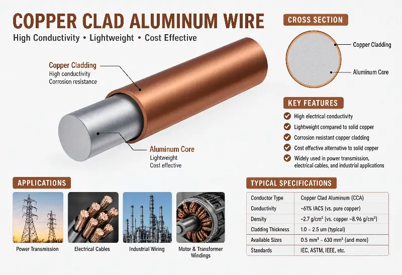
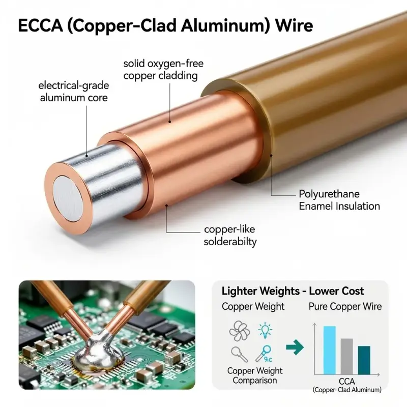
Copper-clad aluminum wire (CCA) exhibits unique advantages in high-frequency scenarios due to its bimetallic structure of a copper layer covering an aluminum core—the copper layer carries the high-frequency current, while the aluminum core provides mechanical support and weight advantages.
This article systematically examines the engineering boundaries and selection logic of CCA wires from six dimensions: the physical mechanism of the skin effect, the penetration depth formula, the impact of frequency on CCA wires, a comparison of the high-frequency properties of copper and aluminum CCA wires, typical engineering applications, and coping strategies. — ## Basic Understanding of the Skin Effect ### Basic Definition The skin effect is a physical phenomenon where, when alternating current passes through a conductor, the current density distribution inside the conductor is uneven, and the current tends to concentrate at the surface of the conductor.
History and Discovery
Essentially, an alternating magnetic field induces eddy electric fields within the conductor, which act in the opposite direction on the current, causing it to concentrate at the surface. ### History and Discovery The skin effect was first systematically studied by the British physicist Horace Lamb in 1883, and Oliver Heaviside provided a complete mathematical derivation in 1885.
After Tesla invented the alternating current system in 1891, the impact of the skin effect on power transmission losses began to receive widespread attention.
Why Skin Effect Matters
With the rise of radio technology in the 20th century, the skin effect became a core consideration in high-frequency circuit design. ### Why is the Skin Effect Important? The skin effect has three core impacts in engineering: 1.
Increased Equivalent Resistance: At high frequencies, current only flows through the surface layer, reducing the equivalent cross-sectional area, and making the AC resistance greater than the DC resistance.
Engineering Boundaries of Skin Effect
Increased Transmission Loss: At high frequencies, copper losses in power transformers and inductors increase, leading to higher temperature rise.
Intensified Signal Attenuation: When high-frequency signals are transmitted along the cable, the attenuation increases with frequency.
Skin Depth Formula and Calculation
Standard Formula
For CCA wires, the thickness of the copper layer directly determines the high-frequency conductivity: When the copper layer thickness is greater than the penetration depth, the high-frequency current flows entirely within the copper layer, and the AC resistance of the CCA wire approaches that of a pure copper wire. ### Engineering Boundaries of Skin Effect The engineering impact of the skin effect varies significantly across different frequency ranges: – DC (0 Hz): No skin effect, current is uniformly distributed across the entire cross-section. – 50/60 Hz Power Frequency: Skin depth approximately 9 mm (copper), minimal impact on conductors with a cross-sectional area of less than 100 mm². – Audio (20 Hz–20 kHz): Skin depth approximately 0.5 mm at 20 kHz, limited impact on ordinary audio cables. – kHz-level Switching Power Supplies: Skin depth 0.2 mm at 100 kHz, requires Litz wire or copper foil. – MHz-level Wireless Charging/Radar: Skin depth 0.05–0.2 mm in the 100 kHz–13.56 MHz range. — ## Penetration Depth Formula and Calculation ### Standard Formula Penetration Depth (Skin Depth, δ) is defined as the depth at which the current density decays to 1/e (approximately 37%) of the surface value.
The formula is: δ = √(2ρ / (ωμ)) = √(ρ / (πfμ)) Where: - δ = Penetration depth (meters) - ρ = Conductor resistivity (Ω·m) - ω = Angular frequency (rad/s) = 2πf - μ = Conductor permeability (H/m) ≈ μ₀μᵣ, copper and aluminum μᵣ≈1 - f = Frequency (Hz) ### Calculation of penetration depth of copper **Copper (pure copper C11000) parameters**: - ρ = 1.678 × 10⁻⁸ Ω·m (20°C) - μᵣ ≈ 1 Substituting into the formula: δ_Cu = √(1.678×10⁻⁸ / (π × f × 4π×10⁻⁷)) = √(1.678×10⁻⁸ / (4π²×10⁻⁷ × f)) = 0.0661 / √f (Unit: meters) | Frequency | Penetration Depth (Copper) | |------|----------------| | 50 Hz | 9.4 mm | | 1 kHz | 2.1 mm | | 10 kHz | 0.66 mm | | 100 kHz | 0.21 mm | | 1 MHz | 66 μm | | 13.56 MHz | 17.7 μm | ### Calculation of Penetration Depth for Aluminum **Aluminum (Pure Aluminum 1350) Parameters**: - ρ = 2.65 × 10⁻⁸ Ω·m (20°C) - μᵣ ≈ 1 δ_Al = √(2.65×10⁻⁸ / (π × f × 4π×10⁻⁷)) = 0.0824 / √f (Unit: meters) “` | Frequency | Penetration Depth (Aluminum) | |——|—————-| | 50 Hz | 11.7 mm | | 1 kHz | 2.6 mm | | 10 kHz | 0.83 mm | | 100 kHz | 0.26 mm | | 1 MHz | 82 μm | | 13.56 MHz | 22.2 μm | ### Skin Behavior of CCA Wire The skin behavior of Copper-clad Aluminum Wire (CCA Wire) exhibits a “double-layer metal” characteristic: – Copper layer: Carries high-frequency current, conductivity close to pure copper – Aluminum core: Carries only low-frequency or DC current The effective high-frequency resistance R_AC/R_DC of CCA wire depends on the ratio of copper layer thickness to penetration depth: – Copper layer thickness >> Penetration depth: High-frequency current is entirely in the copper layer, R_AC ≈ pure copper – Copper layer thickness ≈ Penetration Depth: High-frequency current partially penetrates into aluminum, R_AC is between copper and aluminum – Copper layer thickness << Penetration Depth: High-frequency current penetrates into the aluminum core, R_AC is close to pure aluminum.
Skin Depth Calculation for Copper
| Frequency | Skin Depth (Copper) |
|---|---|
| 50 Hz | 9.4 mm |
| 1 kHz | 2.1 mm |
| 10 kHz | 0.66 mm |
| 100 kHz | 0.21 mm |
| 1 MHz | 66 μm |
| 13.56 MHz | 17.7 μm |
According to ASTM B-566 standard, typical CCA line copper layer volume fraction is 10–15% (Class 10H/15H), corresponding to a radial thickness of approximately 0.05–0.2 mm.
In the 100 kHz–1 MHz frequency band, the copper layer thickness is slightly greater than the penetration depth, CCA high-frequency performance is close to pure copper. — ## The Influence of Frequency on Skin Effect ### DC and Low Frequency (<1 kHz) In DC and low frequency scenarios, the skin depth is much larger than the conductor diameter, and the current is uniformly distributed across the cross-section: – 50/60 Hz power transmission: copper δ ≈ 9.4 mm, much larger than AWG 14–30 wire diameter – Audio (<20 kHz): δ ≈ 0.5 mm, ordinary wires (<0.5 mm diameter) have almost no effect Conclusion: In DC and low frequency scenarios, CCA wire does not have a skin disadvantage, and its performance difference from pure copper wire is entirely determined by DC resistance. ### Mid-Frequency (1 kHz–100 kHz) In the 1 kHz–100 kHz band, the skin depth decreases from 2.1 mm to 0.21 mm: – At 100 kHz, copper δ = 0.21 mm: AWG 26 (0.4 mm diameter) wire still carries 50% of the current cross-section, but the contribution in the center area is significantly reduced. – Switching Power Supply (20–500 kHz): Multi-strand Litz wire (single strand diameter < 50 μm) must be used; ordinary round wire has excessive copper loss. – Audio Crossover (1–10 kHz): δ = 0.66–2.1 mm, the effect is negligible for most audio lines.
Skin Depth Calculation for Aluminum
| Frequency | Skin Depth (Aluminum) |
|---|---|
| 50 Hz | 11.7 mm |
| 1 kHz | 2.6 mm |
| 10 kHz | 0.83 mm |
| 100 kHz | 0.26 mm |
| 1 MHz | 82 μm |
| 13.56 MHz | 22.2 μm |
Conclusion: In the mid-frequency scenario, the skin effect becomes significant but still manageable. AWG 22–30 round wire can still be used at 100 kHz, but copper loss needs to be evaluated. ### High Frequency (100 kHz–1 MHz) In the 100 kHz–1 MHz band, the skin depth decreases to 0.05–0.21 mm: – 100 kHz: δ = 0.21 mm, ordinary AWG 26 round wire is no longer applicable – 500 kHz: δ = 95 μm, Litz wire or copper foil must be used – 1 MHz: δ = 66 μm, the diameter of a single strand of wire should not exceed 4δ ≈ 0.26 mm Conclusion: In high-frequency scenarios, the copper layer of CCA wire has significant advantages—the copper layer carries current, and the ineffective area of the aluminum core does not increase AC resistance. ### Ultra-High Frequency (>1 MHz) In the >1 MHz band (wireless charging, RFID, radar), skin depth decreases to 20–60 μm: – 13.56 MHz (RFID standard): Copper δ ≈ 17.7 μm, Aluminum δ ≈ 22.2 μm – CCA lines with a 50 μm copper layer thickness still outperform pure aluminum lines at 13.56 MHz (copper layer completely covers the penetration depth) – Complete replacement of pure copper: In some coaxial cable applications, CCA can directly replace copper (coaxial structure naturally limits skin depth) Conclusion: In ultra-high frequency scenarios, CCA lines have high-frequency performance close to pure copper, and have significant cost and weight advantages. — ## High-Frequency Property Comparison of Copper vs.
Aluminum vs. CCA ### Property Comparison (Skin Effect Engineering Trade-offs) | Property Parameters | Pure Copper (C11000) | Pure Aluminum (1350) | CCA Wire (15% Copper) | Engineering Impact | |———-|—————-|————–|—————-|———-| | Density (g/cm³) | 8.89 | 2.70 | 3.63 | CCA weighs 41% of copper, slightly heavier than aluminum | | DC Resistivity (×10⁻⁸ Ω·m) | 1.678 | 2.65 | 2.41 | DC performance is 44% worse than copper, 10% better than aluminum | | 100 kHz Skin Depth δ | 0.21 mm | 0.26 mm | 0.21 mm (copper layer) | CCA high-frequency performance is close to copper | | 100 kHz AC Resistance | 1.0× | 1.28× | 1.05–1.10× | CCA high-frequency resistance is only 5–10% higher than copper | | Oxidation Resistance | Excellent | Poor | Excellent (outer copper layer) | CCA oxidation resistance is the same as copper | | Solderability | Excellent (solderable) | Poor (requires special process) | Excellent (copper layer is solderable) | CCA can be directly soldered | | 2026 Price Index | Baseline 100 | 25–35 | 50–65 | CCA cost is 35–50% lower than copper |
Skin Effect Behavior of CCA Wire
DC and Low Frequency (<1 kHz): CCA wire DC resistance is higher than pure copper, but better than pure aluminum.
High Frequency (>100 kHz): CCA copper layer carries current, with performance close to pure copper (difference 5–10%).
Ultra-High Frequency (>100 kHz): MHz: In applications where the skin depth is limited, such as coaxial cables, CCA can directly replace pure copper.
Frequency Impact on Skin Effect
DC and Low Frequency (<1 kHz)
Mechanical Properties: CCA wire is 59% lighter (than copper) and has better tensile strength than pure aluminum. — ## Engineering Impact of Skin Effect on CCA Wire### Increased AC Resistance The most direct engineering impact of the skin effect is that AC resistance R_AC is significantly higher than DC resistance R_DC: – Single-strand round wire (diameter d): When d > 2δ, R_AC/R_DC ≈ d/(2δ) – AWG 18 (1.0 mm diameter) @ 100 kHz: d/(2δ) = 1.0/0.42 ≈ 2.4, meaning the AC resistance is 2.4 times that of DC. – Litz wire (multi-strand thin wire): When the single-strand diameter d << δ, R_AC ≈ R_DC CCA CCA Wire Advantages: The copper layer carries high-frequency current, and R_AC is close to that of pure copper (difference <10%), while the aluminum core area does not increase AC resistance. ### Copper Loss and Temperature Rise: The skin effect directly affects the temperature rise of the transformer/inductor: – Copper Loss P = I² × R_AC: When R_AC increases by 2.4 times, copper loss increases by 140%. – Temperature Rise ΔT ∝ P: The transformer temperature rises from 60°C to 144°C (under the same heat dissipation conditions). – Accelerated Insulation Aging**: Under long-term high temperatures, the aging rate of the enamel coating doubles.
Mid Frequency (1 kHz–100 kHz)
CCA Wire Engineering Significance: In high-frequency transformer design, using CCA wire with an appropriate wire diameter can reduce costs while maintaining high-frequency performance. ### Signal Attenuation in Long-Distance Transmission Scenarios: The skin effect exacerbates high-frequency signal attenuation: – Transmission Line Model: Attenuation constant α = R_AC / (2 × Z₀) – Coaxial Cable: α increases with √f (α increases by ~3 dB/100m for every 10-fold increase in frequency) – Audio/Video Signals: Significant attenuation above 3 MHz
High Frequency (100 kHz–1 MHz)
CCA Coaxial Cable: In frequency bands above 1 MHz, CCA coaxial cable can replace pure copper coaxial cable (with equivalent impedance and attenuation characteristics), which is why HDMI, cable TV, and satellite TV extensively use CCA cables. ### Resonance and Quality Factor (Q) The Q value of high-frequency inductors and resonant circuits is significantly affected by the skin effect: – Q = ωL / R_AC: An increase in R_AC leads to a decrease in Q. – Resonant Circuit: A decrease in Q leads to an increase in bandwidth and a decrease in selectivity. – Filter: An increase in insertion loss.
Ultra-High Frequency (>1 MHz)
CCA Cable Applications: In resonant circuits where Q value requirements are moderate and cost is sensitive (such as wireless charging transmitter coils), CCA cables are the preferred solution. — ## The Influence of Skin Effect on Different Wire Diameters ### The principle of matching wire diameter with penetration depth is to effectively utilize the conductor cross-sectional area.
CCA Wire Applications: – Copper layer thickness 50–100 μm > δ (δ=0.21 mm at 100 kHz), high-frequency current is entirely within the copper layer. – CCA wire replaces pure copper: Performance difference <10%, cost reduction 35–50%. – Applicable specifications: AWG 30–38 CCA single wire or Litz wire.
Engineering Significance: CCA wire has large-scale replacement of pure copper wire in the field of wireless charging, and is a mature solution for cost reduction and efficiency improvement. ### Area 2: Switching Power Supplies (SMPS, 20 kHz–1 MHz) Typical Applications: Mobile phone chargers, laptop adapters, server power supplies, 5G base station power supplies.
High-Frequency Property Comparison: Copper vs Aluminum vs CCA
CCA Wire Applications: – 50 W–500 W power ratings, copper foil tape winding + enameled CCA wire – High-frequency transformer windings use CCA Litz wire – performance close to pure copper, cost advantage of 30–40% Engineering Significance: In low-to-medium power SMPS, CCA wire is a mature alternative to pure copper wire. ### Area 3: Coaxial Cable (1 MHz–3 GHz) Typical Applications: Cable TV, satellite TV, network communication, security monitoring, HDMI cables.
CCA Wire Applications: – Completely replaces pure copper coaxial cable: In frequency bands above 1 MHz, performance difference <5% – Standard RG-6 / RG-11 coaxial cables extensively use CCA inner conductor – center conductor CCA + outer braided aluminum shield + sheath Engineering Significance: CCA coaxial cable is the most mature application in consumer electronics, the optimal balance between performance and cost. ### Area 4: Telecom RF and Wireless Infrastructure (100 MHz–6 GHz) Typical Applications: Base station feeders, antenna connectors, RF cable assemblies.
CCA Wire Applications: – Silver-plated CCA wires directly replace pure copper in frequency bands above 1 GHz – Silver plating layer (0.5–2 μm) + CCA substrate, skin depth less than the silver plating layer – Applicable specifications: AWG 16–24 silver-plated CCA Engineering Significance: Silver-plated CCA is the mainstream solution for 5G/4G base station feeders, costing 40–60% less than pure copper. ### Area 5: Radar and High-Frequency Electronics (1–40 GHz) Typical Applications: Automotive radar (77 GHz), military radar, satellite communications.
CCA Wire Applications: – Silver-plated CCA + High-density polyethylene insulation + Double shielding – For 77 GHz bands with skin depth < 1 μm, silver-plated CCA is mandatory. – Applicable specifications: Semi-rigid cables, flexible coaxial cables.
Engineering Impact of Skin Effect on CCA Wire
AC Resistance Increase
Engineering significance: In the millimeter-wave band, silver-plated CCA is the only economically viable coaxial cable solution. ### Area 6: Induction Heating (10 kHz–1 MHz) Typical Applications: Industrial induction furnaces, induction cookers, induction welding.
CCA Wire Applications: – High-power induction heating (>10 kW) uses copper tubing + water cooling, but low-to-medium power (<5 kW) can use CCA coils. – Low-to-medium power induction heating uses CCA Litz wire windings – Performance close to pure copper, significant cost advantage.
Copper Loss and Temperature Rise
Engineering significance: CCA wire has secured a place in the low-to-medium power induction heating market. ### Area 7: Automotive Electronics (DC–1 MHz) Typical Applications: Automotive wiring harnesses, on-board chargers (OBC), DC-DC converters, motor controllers.
CCA Wire Applications: – Automotive low-voltage wiring harnesses (<60V): CCA wire replaces pure copper, reducing weight by 40–60% – OBC and DC-DC converters use CCA high-frequency transformer windings – Applicable specifications: AWG 14–22 CCA single wire + enameled coating Engineering Significance: The weight of wiring harnesses in new energy vehicles is critical; CCA wire is a mature automotive-grade solution. ### Area 8: Audio and Speakers (20 Hz–20 kHz) Typical Applications: Speaker crossovers, amplifier internal wiring, car audio systems.
Signal Attenuation
CCA Cable Applications: – Skin depth is 0.5 mm at 20 kHz, while ordinary audio cable diameter is 0.5–2.5 mm, minimal skin effect. – CCA audio cables perform less than 1% differently from pure copper (primarily due to DC resistance difference). – However, some high-end audiophiles still believe that CCA affects sound quality (actually a psychological factor).
Engineering Significance: Audio scenarios are the application where CCA cables have the smallest performance disadvantage, but it is also the area with the most brand controversy. — ## Engineering Strategies to Address the Skin Effect### Strategy 1: Use Litz Wire Principle: Reduce the single strand diameter to < δ/2 to achieve uniform current distribution.
Resonance and Quality Factor (Q)
Engineering Parameters: – Single strand diameter: 50–200 μm (depending on frequency) – Number of strands: 5–1000 – Twisting pitch: < 5 times the single strand diameter Applications: Wireless charging, SMPS transformer, induction heating coils. ### Strategy 2: Use copper foil strip winding Principle: Replace round wire with thin copper strip (0.025–0.5 mm), maximizing surface area with a flat shape.
Applications: High-frequency planar transformers, resonant inductors. ### Strategy 3: Use silver-plated/tin-plated copper wire Principle: High-frequency current flows in the plating (thickness > δ), with conductivity the same as pure copper/silver.
Applications: RF coaxial cables, 5G feeders, radar cables. ### Strategy 4: Use CCA wire (copper-clad aluminum) Principle: Utilize the copper layer to carry high-frequency current, eliminating AC resistance in the ineffective areas of the aluminum core.
Impact of Skin Effect on Different Wire Diameters
Wire Diameter vs Skin Depth Matching Principle
| Conductor Diameter | Recommended Max Frequency | Engineering Application |
|---|---|---|
| 0.04 mm (AWG 46) | 10 MHz+ | Litz single strand, UHF windings |
| 0.10 mm (AWG 38) | 5 MHz | Litz single strand, HF transformers |
| 0.25 mm (AWG 30) | 1 MHz | HF transformers, wireless charging |
| 0.40 mm (AWG 26) | 200 kHz | SMPS transformers, audio crossovers |
| 0.64 mm (AWG 22) | 50 kHz | Power frequency + audio |
| 1.00 mm (AWG 18) | 10 kHz | Power + audio |
| 1.63 mm (AWG 14) | 1 kHz | Power windings |
Applications: Wireless charging, SMPS, automotive electronics, coaxial cables. ### Strategy 5: Choose an appropriate operating frequency Principle: Avoid using single-strand thick wires in the 100 kHz–10 MHz frequency band.
Engineering Trade-offs: – Below 100 kHz: Single-strand round wire OK – Above 100 kHz: Litz wire or copper foil – Above 1 MHz: Silver-plated/tin-plated copper wire or copper foil ### Strategy 6: Use hollow conductors (copper tubes) Principle: The hollow structure concentrates the current in a thin surface layer, saving material.
Litz Wire Principle
Applications: High-power induction heating, mid-to-high frequency transformers. — ## CCA Line Skin Effect Project Application Summary The skin effect on CCA lines exhibits a typical frequency-dependent characteristic.
In DC and low-frequency scenarios, the engineering behavior of CCA lines is entirely determined by DC resistance, with the copper layer and aluminum core working together.
As the frequency rises above 100 kHz, the copper layer gradually assumes the main conductive function, while the aluminum core region, due to being “shielded” by the skin effect, contributes little to AC resistance.
Eight Major Typical Application Scenarios
Domain 1: Wireless Charging (100–205 kHz)
When the frequency exceeds 1 MHz, the high-frequency performance of CCA lines approaches that of pure copper lines (and can be directly replaced in coaxial cable structures).
Domain 2: Switching Power Supply (SMPS, 20 kHz–1 MHz)
This is the fundamental reason for the large-scale application of CCA lines in high-frequency scenarios such as wireless charging, 5G feeders, and SMPS. From an application perspective, wireless charging (100–205 kHz), SMPS (20 kHz–1 MHz), coaxial cables (1 MHz–3 GHz), and telecommunications RF (100 MHz–6 GHz) are the four scenarios where CCA lines leverage the skin effect to achieve the greatest engineering value.
Domain 3: Coaxial Cables (1 MHz–3 GHz)
Their common characteristic is that the high-frequency current is confined to the surface by the copper layer, and the aluminum core is harmless to performance.
Domain 4: Telecom RF and Wireless Infrastructure (100 MHz–6 GHz)
Automotive electronics (DC–1 MHz) and audio (20 Hz–20 kHz) are cost-driven applications for CCA wires.
Domain 5: Radar and High-Frequency Electronics (1–40 GHz)
In these scenarios, the skin effect has a minimal impact, and the cost and weight advantages of CCA are the dominant factors.
Domain 6: Induction Heating (10 kHz–1 MHz)
Ultimately, the core of project-based selection of CCA wires in skin effect scenarios lies in establishing a systematic decision-making process of “frequency → penetration depth → copper layer thickness → high-frequency performance”: First, clarify the operating frequency and penetration depth; then confirm the ratio between CCA copper layer thickness and δ (when copper layer thickness > δ, high-frequency performance is close to that of pure copper); finally, ensure high-frequency performance and long-term reliability through standard compliance (ASTM B-566 + IEC 60317) and batch sampling inspection (copper layer thickness, conductivity, crimp strength).
Domain 7: Automotive Electronics (DC–1 MHz)
Discussing “CCA replacing copper” without considering frequency is meaningless—only when CCA wires are placed in the correct frequency range and engineering structure can they truly realize the comprehensive engineering value of high-frequency performance + cost advantage + weight advantage.
Domain 8: Audio and Speakers (20 Hz–20 kHz)
Engineering Strategies to Counter Skin Effect
Strategy 1: Use Litz Wire
Litz wire employs multiple strands of fine enameled wire twisted together, with each individual strand diameter far smaller than the skin depth, so that R_AC ≈ R_DC. The single-strand diameter is typically 50–200 μm depending on frequency, with strand counts ranging from 5 to 1000, and the lay length less than 5 times the single-strand diameter to ensure uniform distribution. Typical applications include wireless charging, SMPS transformers, and induction heating coils.
Strategy 2: Use Copper Foil Strip Windings
Copper foil strip windings use thin copper strips (0.025–0.5 mm thickness) to replace round wires, with the flat geometry maximizing surface area. This approach is widely used in high-frequency planar transformers and resonant inductors, where it can reduce AC resistance by 30–50% compared to round wire of equivalent cross-sectional area.
Strategy 3: Use Silver/Tin-Plated Copper Wire
The high-frequency current flows within the plating layer (when plating thickness exceeds skin depth), giving the same conductivity as pure copper or silver. Typical plating thicknesses are 0.5–2 μm for silver plating, suitable for RF coaxial cables, 5G feeder lines, and radar cables operating above 1 GHz.
Strategy 4: Use CCA Wire (Copper Clad Aluminum)
CCA wire leverages the copper layer to carry high-frequency current, while the aluminum core region (beyond skin depth) contributes negligibly to AC resistance. This approach is the most cost-effective for wireless charging, SMPS, automotive electronics, and coaxial cable applications, with cost savings of 35–50% compared to pure copper.
Strategy 5: Choose Appropriate Operating Frequency
Avoid using single-strand thick conductors in the 100 kHz–10 MHz frequency range. Below 100 kHz, single-strand round wire is acceptable; above 100 kHz, Litz wire or copper foil should be used; above 1 MHz, silver-plated/tin-plated copper wire or copper foil is preferred. Frequency selection can dramatically affect conductor cost and AC resistance.
Strategy 6: Use Hollow Conductors (Copper Tubes)
Hollow conductor structures concentrate current in the surface thin layer, saving material while reducing skin-effect losses. This approach is applied in high-power induction heating and medium-to-high frequency transformers where water-cooling tubes serve double duty as electrical conductors and coolant channels.
Project Application Summary of Skin Effect on CCA Wire
The impact of skin effect on CCA wire exhibits a clear frequency-dependent engineering characteristic. At DC and low frequencies, CCA wire’s engineering behavior is entirely determined by DC resistance, with the copper layer and aluminum core working together; when frequency rises above 100 kHz, the copper layer gradually assumes the main current-carrying function, while the aluminum core region contributes negligibly to AC resistance due to being ‘shielded’ by the skin depth; when frequency exceeds 1 MHz, CCA wire’s high-frequency performance approaches that of pure copper wire (can directly substitute in coaxial cable structures), which is the fundamental reason why CCA wire is widely applied in high-frequency scenarios such as wireless charging, 5G feeder lines, and SMPS.
From an application perspective, wireless charging (100–205 kHz), SMPS (20 kHz–1 MHz), coaxial cables (1 MHz–3 GHz), and telecom RF (100 MHz–6 GHz) are the four major scenarios where CCA wire leverages skin effect to achieve maximum engineering value. Their common characteristic is that high-frequency current is confined to the copper layer, and the aluminum core is harmless to performance. Automotive electronics (DC–1 MHz) and audio (20 Hz–20 kHz) are cost-driven applications for CCA wire, where skin effect has minimal impact, and CCA’s cost and weight advantages are the dominant factors.
Ultimately, the project-based selection core of CCA wire in skin effect scenarios lies in establishing a systematic decision process of ‘frequency → skin depth → copper layer thickness → high-frequency performance’: first clarify the operating frequency and skin depth, then confirm the ratio between CCA copper layer thickness and δ (when copper layer thickness > δ, high-frequency performance approaches pure copper), and finally ensure high-frequency performance and long-term reliability through standard compliance (ASTM B-566 + IEC 60317) and batch sampling inspection (copper layer thickness, conductivity, crimp strength). Discussing ‘CCA replacing copper’ out of the context of frequency is meaningless—only by placing CCA wire in the correct frequency range and engineering structure can it truly leverage its combined engineering advantages of high-frequency performance, cost advantage, and weight advantage.