


Transformer Winding Copper Wire: Types and Uses Transformers are core electromagnetic components in power systems, electronic equipment, telecommunications networks, and industrial control, and their performance is highly dependent on the engineering characteristics of the winding copper wire.
Transformer winding copper wire is not a single product, but rather a comprehensive system of engineering materials finely categorized by conductor shape, insulation type, enamel coating grade, and thermal stability grade. From large flat wire windings for power transformers to Litz wires in high-frequency switching power supplies, and even the fine enameled wires for instrument transformers, the selection of winding copper wire directly determines the transformer’s efficiency, temperature rise, lifespan, noise level, and safety rating.
This article systematically outlines the engineering boundaries and selection logic of transformer winding copper wire from eight dimensions: definition, conductor classification, insulation classification, key parameters, transformer type mapping, copper-aluminum engineering comparison, typical applications, and selection process. —Basic Understanding of Transformer Winding Copper WireBasic Definition Transformer winding copper wire refers to the electrical copper conductor used for winding transformer coils, typically enameled copper wire/magnet wire or specially insulated copper wire (such as paper-insulated copper wire or fiberglass-insulated copper wire).
Basic Understanding of Transformer Winding Copper Wire
Basic Definition
High conductivity: Copper has a conductivity of 100% IACS, 1.6 times that of aluminum (61% IACS).
Under the same resistance, the cross-sectional area of copper wire is 35–40% smaller than that of aluminum wire, contributing to transformer miniaturization.
Why Transformers Prefer Copper Wire
High Mechanical Strength: Annealed copper has a tensile strength of approximately 220 MPa, which is 2–3 times that of aluminum (70–95 MPa).
Copper wire has strong resistance to vibration and short-circuit impact, resulting in a longer transformer lifespan.
Special Engineering Requirements for Transformer Winding Copper Wire
Good Oxidation Resistance and Solderability: Copper is not easily oxidized, resulting in high reliability of connection points and facilitating winding welding and maintenance.
Special Engineering Requirements for Transformer Winding Copper Wire Compared to ordinary enameled wire, transformer winding copper wire must meet higher engineering requirements: – High Temperature Resistance: Transformer operating temperatures can reach 130–220°C (depending on the thermal class), requiring the enameled coating to not age or crack under long-term high temperatures. – Voltage Resistance: Voltage between power transformer windings can reach 10–35 kV, requiring the enameled coating to have sufficient dielectric strength. – Oil Resistance: Oil-immersed transformer windings are constantly submerged in mineral oil, requiring the enamel coating to be oil-resistant and chemically corrosion-resistant. – Winding Performance: The enamel coating must not crack or peel off during high-speed winding on a transformer winding machine. – Long-Term Thermal Aging Performance: Transformers are designed for a lifespan of 20–30 years, requiring the enamel coating to possess excellent long-term thermal stability. –Classification by Conductor Shape (Round Wire / Flat Wire / Strip / Multistrand)Round Wire: Round enameled copper wire is the most common type of transformer winding copper wire.
It has a perfectly circular cross-section, with a typical diameter range of AWG 10–44 (0.05–2.6 mm). – Advantages: Mature manufacturing process, simple winding equipment, low cost, and strong versatility. – Disadvantages: Lower space utilization (gap exists in the rectangular slot for circular cross-sections). – Typical Applications: Low-frequency power, audio, signal, and choke coils. – Winding Methods: Layered winding, disc winding, and random winding are all possible.
Flat wire (Flat / Rectangular Wire) The cross-section of flat enameled copper wire is rectangular, with a thickness typically 0.8–6.0 mm and a width 2.0–16.0 mm. – Advantages: High slot fill factor (up to 90%+), large heat dissipation area, significant advantages in low-voltage, high-current scenarios. – Disadvantages: Complex winding process, requires specialized flat winding equipment, insulation at corners is easily damaged. – Typical Applications: High-power power transformers (1000 kVA and above), power distribution transformers (250–2500 kVA), wind power/photovoltaic main transformers. – Key Specifications: Width-to-thickness ratio is typically 4–10 (to avoid stress concentration at corners).
Classification by Conductor Shape (Round / Flat / Foil / Multi-strand)
Round Wire
Foil/Strip Copper foil strip winding uses high-purity copper strip with a thickness of 0.025–0.5 mm as the conductor. – Advantages: Ultra-thin, multi-layer winding possible, extremely low leakage inductance, excellent heat dissipation – Disadvantages: The insulation layer requires Nomex paper or polyester film; complex end connections – Typical Applications: High-frequency switching power supply (SMPS), planar transformer, resonant inductor – Key Processes: The copper strip needs to be pre-coated with an insulation layer (such as 3M polyester tape), and then hot-pressed after winding.
Foil / Strip Wire
1 MHz), Wireless Charging Coil, Induction Heating, RFID Reader – Frequency Range: Typical 20 kHz–13.56 MHz (Wireless Charging Qi Standard 100–205 kHz)Conductor Shape Selection Decision | Conductor Shape | Applicable Frequency | Applicable Power | Typical Applications | |———-|———-|———-|———-| | round wire | DC–10 kHz | <500 kVA | General purpose transformer, signal transformer | | flat wire | 50/60 Hz | >250 kVA | Power transformer, distribution transformer | | Copper Foil Strip | 1 kHz–500 kHz | 1–50 kVA | SMPS, planar transformer | | Litz Wire | 20 kHz–13.56 MHz | <10 kVA | High-frequency transformers, wireless charging | —Classification by insulation type (enameled/paper-coated/fiberglass-coated/double-layer composite)Enameled Copper Wire Enameled copper wire is the most common insulation form for transformer windings.
Multi-strand / Litz Wire
Classified by enamel coating: – Polyurethane (UEW): Temperature resistance 130/155°C, good solderability (no need for scraping), suitable for small transformers. – Polyester (PEW): Temperature resistance 155°C, excellent cost-performance ratio, strong versatility. – Polyester Imide (EIW): Temperature resistance 180°C, thermal shock resistant, the first choice for mid-to-high-end transformers. – Polyamide Imide (AIW): Temperature resistance 200–220°C, excellent chemical resistance, suitable for extreme high-temperature environments.
Conductor Shape Selection Decision
| Conductor Shape | Applicable Frequency | Applicable Power | Typical Application |
|---|---|---|---|
| Round Wire | DC–10 kHz | <500 kVA | General Transformers, Signal Transformers |
| Flat Wire | 50/60 Hz | >250 kVA | Power Transformers, Distribution Transformers |
| Copper Foil | 1 kHz–500 kHz | 1–50 kVA | SMPS, Planar Transformers |
| Litz Wire | 20 kHz–13.56 MHz | <10 kVA | High-Frequency Transformers, Wireless Charging |
Polyimide (PIW): Temperature resistance 220–240°C, highest level, radiation resistant.
Paper Insulated Copper Wire: Paper insulated copper wire uses cable paper or NOMEX paper as the insulation layer (thickness 0.05–0.25 mm), with an outer enameled layer that can be layered on top. – Advantages: High temperature resistance (NOMEX paper withstands 220°C), oil resistance, high dielectric strength (>10 kV/mm). – Disadvantages: Large space requirement, complex manufacturing process, high cost. – Typical Applications: Oil-immersed power transformers, high-power rectifier transformers, high-voltage testing transformers.
Fiberglass Covered Copper Wire: Fiberglass covered copper wire is made by weaving glass fiber yarn around bare copper or enameled copper, then impregnating it with silicone or polyester resin. – Advantages: Temperature resistance up to H/C class (180–220°C), extremely high mechanical strength, fire resistant. – Disadvantages: Poor flexibility, large bending radius. – Typical Applications: Dry-type transformers, traction transformers (rail transit), special transformers of H class and above.
Double-Layer Composite Insulation (Double Insulation) Double-layer composite insulation combines the advantages of two materials: – Enameled + Paper Wrapped: Inner layer UEW/PEW (temperature resistant, easy to wind) + Outer layer NOMEX paper (reinforced voltage resistance) – Enameled + Fiberglass Wrapped: Inner layer EIW (heat resistant) + Outer layer fiberglass (mechanical protection) – Typical Applications: H class dry-type transformers, locomotive traction transformers, ship transformers.
Classification by Insulation Type (Enameled / Paper / Fiberglass / Double Composite)
Enameled Copper Wire
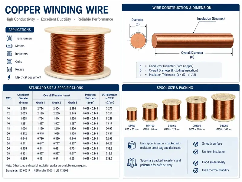
- Grade 1 (Thin Enamel): Minimal enamel coating increments, suitable for high frequency and low voltage.
Paper Insulated Copper Wire
Grade 2 (Standard Enamel): General-purpose, preferred for transformer windings.
Fiberglass Covered Copper Wire
Grade 3 (Thick Enamel): High insulation strength, suitable for high voltage transformers.
Double Layer Composite Insulation
Thermal Class (Thermal Class) According to IEC 60085 / UL 1446 standards: – Class B (130°C): Household transformers, small power supplies – Class F (155°C): General industrial transformers, motors – Class H (180°C): Dry-type transformers, traction transformers – Class N (200°C): Extreme high temperature scenarios – Class R (220°C): Aerospace, special equipmentKey Electrical Parameters – Conductor Resistivity: ≤ 1.724 × 10⁻⁸ Ω·m (100% IACS) – Dielectric Strength (enamel coating): ≥ 4 kV (single layer Grade 2) – Breakdown Voltage: ≥ IEC 60317 standard (varies depending on wire diameter and grade) – Pinhole Count: ≤ 5/30 m (enamel coating integrity)Key Mechanical Parameters – Elongation: ≥ 30% (soft annealed copper) – Tensile Strength: 200–250 MPa (annealed state) – Bending Performance: ≤ 1 × diameter without cracking —Transformer Type and Winding Copper Wire Mapping (Key Engineering Decision Table)Six Transformer Types and Recommended Copper Wires | Transformer Type | Power Range | Frequency | Recommended Conductor | Recommended Insulation | Typical AWG | |————|———-|——|———-|———-|———-| | Power Transformer | 500 kVA–500 MVA | 50/60 Hz | Flat wire / Round wire | Paper-clad / Enameled | AWG 14–10 | | Power Distribution Transformer | 50–2500 kVA | 50/60 Hz | Flat wire / Round wire | Enameled + Paper | AWG 16–12 | | High-Frequency Switching Power Supply (SMPS) Transformer | 50 W–10 kW | 20 kHz–1 MHz | Litz wire / Copper foil | Enameled / Triple insulation | AWG 24–38 | | Isolation Transformer | 100 VA–100 kVA | 50/60 Hz–400 Hz | Round wire / Flat wire | Enameled + Fiberglass | AWG 18–14 | | Instrument Transformer (CT/PT) | <5 kVA | 50/60 Hz | Round wire (fine) | Enameled | AWG 26–36 | | Audio Transformer | <500 W | 20 Hz–20 kHz | Round wire (fine) | Enameled (high purity copper) | AWG 24–32 |Core Selection Logic 1.
Insulation Type Selection Decision
| Insulation Type | Thermal Class | Voltage Resistance | Typical Scenario |
|---|---|---|---|
| Enameled Copper Wire | 130–220°C | Medium (<5 kV) | General Transformers |
| Paper Insulated Copper Wire | 105–220°C | High (>10 kV) | Oil-Immersed Power Transformers |
| Fiberglass Covered Copper Wire | 180–220°C | Medium–High | Dry-Type Transformers, Traction Transformers |
| Double Layer Composite | 180–220°C | High | H-Class Special Transformers |
Frequency determines conductor shape: – 50/60 Hz → Round wire / Flat wire – kHz level → Round wire / Litz wire – 100 kHz+ → Litz wire / Copper foil 2.
Power determines conductor cross-section: – High power → Flat wire (heat dissipation + slot fill factor) – Medium and low power → Round wire (general purpose) – Micro power → 3.
Voltage determines insulation thickness: – Low voltage (<1 kV) → Grade 2 enamel coating – Medium voltage (1–35 kV) → Grade 3 enamel coating + paper sheath – High voltage (>35 kV) → Multi-layer paper sheath + oil immersion 4.
Environment determines insulation system: – Oil immersion environment → Paper sheath – Dry high temperature → Fiberglass sheath/Double-layer composite – Conventional environment → Enamelled coating —Copper winding vs. aluminum winding engineering comparisonProperty comparison (core engineering trade-offs) | Property parameters | Pure copper (C11000) | Pure aluminum (1350) | Engineering impact | |———-|—————-|————–|———-| | Density (g/cm³) | 8.89 | 2.70 | Copper weight 3.3 times | | DC conductivity (%) IACS | 100% | 61% | Copper is 1.6 times better | Tensile strength (MPa) | 220 | 70–95 | Copper is 2.5 times better | Thermal conductivity (W/m·K) | 391 | 237 | Copper has 1.6 times better heat dissipation | Coefficient of linear expansion (×10⁻⁶/°C) | 17 | 23 | Copper is more stable | Oxidation resistance | Excellent | Poor (requires coating protection) | Copper is reliable | 2026 price index | Baseline 100 | 25–35 | Copper is 3 times more expensive |Engineering advantages of copper windings 1.
Small size: Under the same resistance, the cross-sectional area of copper wire is 35–40% smaller than that of aluminum, and the size of the transformer can be reduced by 30–50%.
Key Technical Parameters of Transformer Winding Copper Wire
Conductor Diameter and AWG Specifications
| AWG | Diameter (mm) | Cross-sectional Area (mm²) | Typical Ampacity (A) | Typical Application |
|---|---|---|---|---|
| AWG 14 | 1.63 | 2.08 | 15–20 | High-power Power Frequency Transformers |
| AWG 18 | 1.02 | 0.82 | 7–10 | Medium Power Transformers |
| AWG 22 | 0.64 | 0.33 | 4–6 | Small Power Transformers |
| AWG 26 | 0.40 | 0.13 | 2–3 | Signal Transformers, Pulse Transformers |
| AWG 30 | 0.25 | 0.05 | 1–2 | High-Frequency Transformers, Precision Instruments |
| AWG 38 | 0.10 | 0.008 | <0.5 | Micro Transformers, Medical Devices |
High Efficiency: Copper’s low resistivity results in 25-40% lower load losses for copper transformers compared to aluminum transformers.
Strong Short-Circuit Resistance: Copper’s high mechanical strength allows it to withstand short-circuit current surges 2-3 times stronger.
Enamel Thickness Grade
Long Lifespan: Copper’s good oxidation resistance allows for a transformer lifespan of over 30 years (compared to approximately 20 years for aluminum transformers).
Easy Maintenance: Copper windings offer reliable connections and are less prone to breakage during maintenance.
Thermal Class
Engineering Advantages of Aluminum Windings 1.
Lightweight: Aluminum transformers are 40-50% lighter than copper transformers, facilitating lifting and transportation.
Key Electrical Parameters
Low Cost: The total cost of aluminum transformer windings is 20-30% lower than that of copper windings.
Abundant Resources: Aluminum reserves are 1000 times that of copper, ensuring a stable supply.
Key Mechanical Parameters
Selection Decision – Copper Preferred: Power Transformer, Distribution Transformer, High-Frequency Switching Power Supply, Traction Transformer, Precision Instrument Transformer – Aluminum Can Be Considered: Low-Cost Distribution Transformer (Some Non-Critical Scenarios), Mobile Devices with Extremely High Lightweight Requirements —Detailed Explanation of 6 Typical Application Areas of Transformer Winding Copper WireArea 1: Power Transformer (Power System Main Grid) Typical Applications: Power Plant Step-Up Transformer, Substation Main Transformer, Urban Power Grid Hub.
Copper Wire Requirements: – Conductor: Large cross-section flat wire (50–500 mm²) – Insulation: Paper sheathing (cable paper/NOMEX paper) + oil impregnation – Temperature resistance: Class A (oil impregnation 105°C) to Class H (dry type 180°C) – Capacity: 500 kVA–500 MVA Advantages of Copper Wire: Low loss, high efficiency, long lifespan, making it an irreplaceable choice for the main power grid.
Transformer Type and Winding Copper Wire Mapping (Key Engineering Decision Table)
Six Major Transformer Types and Recommended Copper Wire
| Transformer Type | Power Range | Frequency | Recommended Conductor | Recommended Insulation | Typical AWG |
|---|---|---|---|---|---|
| Power Transformer | 500 kVA–500 MVA | 50/60 Hz | Flat Wire / Multi-strand Round | Paper / Enameled | AWG 14–10 |
| Distribution Transformer | 50–2500 kVA | 50/60 Hz | Round Wire / Flat Wire | Enameled + Paper | AWG 16–12 |
| High-Frequency Switching Power Supply (SMPS) Transformer | 50 W–10 kW | 20 kHz–1 MHz | Litz Wire / Copper Foil | Enameled / Triple Insulated | AWG 24–38 |
| Isolation Transformer | 100 VA–100 kVA | 50/60 Hz–400 Hz | Round Wire / Flat Wire | Enameled + Fiberglass | AWG 18–14 |
| Instrument Transformer (CT/PT) | <5 kVA | 50/60 Hz | Round Wire (Fine) | Enameled | AWG 26–36 |
| Audio Transformer | <500 W | 20 Hz–20 kHz | Round Wire (Fine) | Enameled (High-Purity Copper) | AWG 24–32 |
Area 2: Power Distribution Transformer (Urban/Industrial Power Distribution Network) Typical Applications: 10 kV/0.4 kV pole-mounted transformers, factory power distribution transformers, commercial building transformers.
Copper Wire Requirements: – Conductor: Round wire (AWG 12–16) + Flat wire (>250 kVA) – Insulation: Enameled + Kraft paper/NOMEX paper – Capacity: 50–2500 kVA Advantages of Copper Wire: Small size, low noise, low loss, suitable for densely populated urban environments.
Selection Core Logic
Area 3: High-Frequency Switching Power Supply (SMPS) Typical Applications: Mobile phone chargers, laptop adapters, server power supplies, 5G base station power supplies, photovoltaic inverters, UPS.
Copper Wire Requirements: – Conductor: Litz wire (multi-strand stranded) or copper foil tape – Insulation: Enameled (Grade 1) + Triple Insulated Wire – Frequency: 20 kHz–1 MHz – Capacity: 50 W–10 kW Advantages of Copper Wire: High high-frequency conductivity (Litz wire suppresses skin effect), good heat dissipation, high efficiency.
Copper Winding vs Aluminum Winding Engineering Comparison
Physical Property Comparison (Core Engineering Trade-offs)
| Physical Property | Pure Copper (C11000) | Pure Aluminum (1350) | Engineering Impact |
|---|---|---|---|
| Density (g/cm³) | 8.89 | 2.70 | Copper 3.3 times heavier |
| DC Conductivity (% IACS) | 100% | 61% | Copper 1.6 times better |
| Tensile Strength (MPa) | 220 | 70–95 | Copper 2.5 times higher |
| Thermal Conductivity (W/m·K) | 391 | 237 | Copper 1.6 times better heat dissipation |
| Linear Expansion Coefficient (×10⁻⁶/°C) | 17 | 23 | Copper more stable |
| Oxidation Resistance | Excellent | Poor (requires coating) | Copper more reliable |
| 2026 Price Index | Baseline 100 | 25–35 | Copper 3 times more expensive |
Area 4: Traction Transformer (Rail Transmission) Typical Applications: Electric locomotive traction, EMU (Electric Multiple Unit) traction, Metro traction, Maglev train traction.
Engineering Advantages of Copper Windings
Copper Wire Requirements: – Conductor: Round wire + Flat wire – Insulation: Fiberglass-coated + Enamelled composite (H/C grade) – Temperature Resistance: H grade (180°C) to C grade (220°C) – Special Requirements: Vibration resistance, shock resistance, flame retardancy, low smoke Copper Wire Advantages: High strength, vibration resistance, flame retardancy, meets EN 45545-2 HL3 fire protection standard.
Engineering Advantages of Aluminum Windings
Area 5: Instrumentation Transformer (Current Transformer CT / Voltage Transformer PT) Typical Applications: Power system metering, protective relays, power grid monitoring, industrial control measurement.
Selection Decision
Copper Wire Requirements: – Conductor: Fine round wire (AWG 26–36) – Insulation: Enameled (Grade 2) – Precision: High (error <0.5%) Advantages of Copper Wire: High purity (OFC oxygen-free copper) ensures high precision, good stability, and high long-term reliability.
Field 6: Special Transformers (Aerospace, Medical, Military) Typical Applications: Spacecraft power supply transformers, medical MRI transformers, military communication transformers, shipboard transformers.、
Six Major Typical Application Areas of Transformer Winding Copper Wire
Area 1: Power Transformers (Power System Main Grid)
/ Copper Foil | | Low Power, High Frequency | Multi-strand Litz Wire |Step 3: Determine Insulation Type and Thermal Class By Voltage → Insulation, By Temperature → Temperature Resistance, By Environment → System: – Low Voltage → Enameled – Medium Voltage → Enameled + Paper Sheath – High Voltage → Multi-layer Paper Sheath + Oil Impregnation – Dry High Temperature → Fiberglass Sheath / Double-layer CompositeStep 4: Matching Standards and Certifications – International Standards: IEC 60317 (Enameled Copper Wire) / IEC 60076 (Transformer) / IEC 60085 (Thermal Class) – US Standards: NEMA MW 1000 (Enameled Copper Wire) / UL 1446 (Insulation System) – Chinese Standards: GB/T 6109 (Enameled Copper Wire) / GB/T 1094 (Transformer) – Industry Standards: IEEE C57.12.00 (General Requirements for Electrical Transformers)Step 5: Supplier Evaluation and Batch Sampling Inspection Supplier Qualifications: – ISO 9001 Basic Quality Management System – IATF 16949 (e.g., automotive electronics) – AS9100 (e.g., aerospace) – UL Approval (North American Market) Batch Sampling Inspection Items: – Conductor Diameter (Tolerance ±0.005 mm) – Enamel Coating Thickness (according to Grade requirements) – Conductor Resistivity (≤ 1.724 × 10⁻⁸ Ω·m) – Breakdown Voltage (≥ Standard Value) – Enamel Coating Continuity (Pinhole Test, according to IEC 60851) – Elongation (≥ 30%) – Appearance (No Joints, No Enamel Coating Damage) —Summary of Transformer Winding Copper Wire Project Applications: Transformer winding copper wire is a type of electrical wire product with distinctive engineering characteristics and diverse application scenarios.
Area 2: Distribution Transformers (Urban / Industrial Distribution Grid)
Its engineering value highly depends on the precise matching of transformer type and copper wire type.
Area 3: High-Frequency Switching Power Supply (SMPS) Transformers
Understanding the essential differences between copper and aluminum windings—clearly recognizing copper’s comprehensive advantages in conductivity, mechanical strength, oxidation resistance, and lifespan, as well as aluminum’s localized advantages in weight and cost—is the fundamental judgment for engineers when selecting transformer windings.
Area 4: Traction Transformers (Rail Transit)
From the perspective of transformer type, power transformers (500 kVA–500 MVA), distribution transformers (50–2500 kVA), and high-frequency switching power supply transformers (SMPS) are the three main markets for transformer winding copper wire, corresponding to three different copper wire technology routes: flat wire/paper insulation, round wire + flat wire composite, and Litz wire/copper foil, respectively.
Area 5: Instrument Transformers (Current Transformer CT / Potential Transformer PT)
Traction transformers, instrumentation transformers, and special transformers represent high-value-added applications of transformer winding copper wire, imposing more stringent requirements on the copper wire’s temperature resistance, vibration resistance, flame retardancy, and radiation resistance. Ultimately, the core of project-based selection for transformer winding copper wire lies in establishing a systematic decision-making process of “transformer type → operating frequency → power level → environmental conditions”: first, clarify the transformer’s engineering positioning, then match the conductor shape, insulation type, and thermal class of the copper wire, and finally ensure the transformer’s long-term reliability through strict standard compliance and batch sampling inspection. Discussing “copper wire vs. aluminum wire” without considering transformer type is meaningless—only by placing the copper winding in the correct transformer type can it truly realize its comprehensive engineering advantages of high efficiency, low power consumption, and long lifespan.
Transformer Winding Copper Wire Project Application Summary
Transformer Winding Copper Wire Selection 5-Step Method
Step 1: Define Transformer Type and Operating Conditions. The first step is to clearly define the transformer type and operating conditions, including transformer category, operating frequency, power level, and environmental conditions.
Step 2: Select Conductor Shape and Specifications. According to the operating frequency and power level, select the appropriate conductor shape: flat wire for high-power low-frequency, round wire for medium-power low-frequency, Litz wire for kHz level, copper foil for high-frequency.
Step 3: Determine Insulation Type and Thermal Class. Based on voltage level, temperature requirement, and environmental conditions, determine the insulation type: enameled for low voltage, paper-wrapped for medium voltage, multi-layer paper + oil immersion for high voltage, fiberglass-wrapped for dry-type high temperature.
Step 4: Match Standards and Certifications. Verify that the selected copper wire complies with relevant standards: IEC 60317 (enameled copper wire), IEC 60076 (transformer), IEC 60085 (thermal class), NEMA MW 1000, UL 1446, GB/T 6109, IEEE C57.12.00.
Step 5: Supplier Evaluation and Batch Sampling Inspection. Evaluate the supplier’s qualifications (ISO 9001, IATF 16949, AS9100, UL certification), and conduct batch sampling inspection on conductor diameter, enamel thickness, conductivity, breakdown voltage, enamel continuity (pinhole test), elongation, and appearance. engineering characteristics and diverse application scenarios. Its engineering value highly depends on the precise matching between transformer type and copper wire type. Understanding the essential differences between copper windings and aluminum windings—clearly recognizing copper’s comprehensive advantages in conductivity, mechanical strength, oxidation resistance, and lifespan, as well as aluminum’s localized advantages in weight and cost—is the foundational engineering judgment for transformer winding selection.
From the perspective of transformer types, power transformers (500 kVA–500 MVA), distribution transformers (50–2500 kVA), and high-frequency switching power supply (SMPS) transformers are the three major markets for transformer winding copper wire, corresponding to three different copper wire technology routes: flat wire/paper insulation, round wire + flat wire composite, and Litz wire/copper foil. Traction transformers, instrument transformers, and special transformers are high value-added uses of transformer winding copper wire, imposing more stringent requirements on copper wire’s heat resistance, vibration resistance, flame retardancy, and radiation resistance.
Finally, the project-based selection core of transformer winding copper wire lies in establishing a systematic decision-making process of ‘transformer type → operating frequency → power level → environmental conditions’: first clarify the engineering positioning of the transformer, then match the copper wire’s conductor shape, insulation type, and thermal class, and finally ensure the transformer’s long-term reliability through strict standard compliance and batch sampling inspection. Discussing ‘copper wire vs aluminum wire’ out of context of transformer type is meaningless—only by placing copper windings in the correct transformer type can they truly leverage their combined engineering advantages of high efficiency, low loss, and long lifespan.