


Design Principles of Transformer Core Coils and the Positioning of Paper‑Covered Wire
Transformer core coils are complete sets of windings mounted on the core limbs, comprising the high‑voltage winding (HV), low‑voltage winding (LV), tap winding, balance winding, compensating winding, and shielding winding. In oil‑immersed power transformers, core coils typically employ rectangular copper conductors insulated with cellulose paper—known as paper‑covered wire (PCW)—to provide both main insulation and turn‑to‑turn insulation, making this approach a key insulation solution for core electromagnetic equipment.
The fundamental electromagnetic relationships in core coil design are governed by three equations: 1) the voltage per turn et = 4.44·f·N·B·A_Fe (where f is 50/60 Hz, B is 1.5–1.8 T for silicon steel sheets or 1.2–1.5 T for amorphous alloys); 2) the winding reactance X% = 2πf·μ₀·N²·A_leakage / (H·U_N²) (with μ₀ = 4π × 10⁻⁷ H/m and A leakage being the leakage flux area), which determines the impedance voltage (typically 6–12%) and the short‑circuit current (I_sc = I_N / X%); and 3) the product of the winding current density J (A/mm²) and the magnetic flux density B, J·B, which controls the volume utilization factor of the core–winding assembly (250–400 (A/mm²)·T for power transformers, 150–250 (A/mm²)·T for dry‑type transformers).
Within the core coil, paper‑covered wire establishes a comprehensive paper insulation system, including turn‑to‑turn insulation, disc‑to‑disc insulation, section‑to‑section insulation, end‑ring insulation, main insulation, and oil‑channel insulation. In 35 kV–1000 kV oil‑immersed transformers, the “oil–paper” synergistic insulation system formed by paper‑covered wire and mineral oil achieves a dielectric strength of up to 30 kV/mm in the oil‑immersed state—nearly four times that of air‑impregnated paper insulation (8 kV/mm)—making it an indispensable main insulation solution today.
Coupled Design of Conductor Materials and Insulation Systems in Paper Covered Wire
Definition, Evolution, and Core Value of Paper Covered Wire
Paper‑wrapped wire (PCW) is an electromagnetic wire product formed by continuously or semi‑overlappingly winding insulating paper tape—made of cellulose or modified cellulose—around rectangular (flat) or circular copper (or aluminum) conductors. It serves as the core insulation solution for the windings of large electromagnetic equipment, including oil‑immersed power transformers, distribution transformers, HVDC converter transformers, electric furnace transformers, rectifier transformers, traction transformers, wind‑and‑photovoltaic step‑up transformers, and main transformers for nuclear power plants. First applied to oil‑immersed transformers in the late 19th century, PCW now boasts over 130 years of history. Its five major advantages—mature manufacturing processes, reliable insulation performance, synergistic oil‑paper dielectric properties, environmental robustness, and recyclability—have made it an irreplaceable choice for transformer winding insulation.
The core value of paper‑wrapped wire is embodied in four key aspects: ① High dielectric strength—the synergistic oil‑paper insulation achieves a dielectric strength of 30 kV/mm under oil immersion, nearly four times that of air‑impregnated paper insulation (8 kV/mm); a single layer of 0.10 mm cable paper can withstand 1.5–2.5 kV at power frequency. ② Excellent thermal stability—high‑quality TUK‑modified paper offers a service life exceeding 30 years at continuous operation up to 120°C, and still maintains more than 15 years of operational life at 130°C. ③ High mechanical strength—after vacuum pressure oil impregnation, the cellulose paper and copper conductor form a tightly integrated structure capable of withstanding the transient impacts of short‑circuit electromagnetic forces (F = μ₀·N²·i_sc²·A_leakage / 4π·H_m²). ④ Environmental compatibility—the paper‑based material is 100% biodegradable; when paired with natural esters (FR3), complete biodegradability upon decommissioning is achieved, reducing the carbon footprint by 30–50% compared to enamel wire solutions.
Specifications for Conductor Materials in Paper Covered Wire
The conductor materials for paper‑wrapped wire are predominantly high‑purity electrolytic copper (C11000 ETP), with a copper content ≥99.90%, oxygen content ≤0.04%, volume resistivity ≤0.01724 Ω·mm²/m at 20°C, IACS conductivity ≥100%, elongation (soft state) ≥35%, and tensile strength of 200–250 MPa. A small proportion of aluminum conductors (C1350‑O / 6101‑T81) is used in cost‑ or weight‑sensitive transmission and distribution applications, featuring an aluminum content ≥99.5%, volume resistivity ≤0.0283 Ω·mm²/m at 20°C, IACS conductivity ≥61%, and elongation ≥20%.
Rectangular (flat) conductors are the dominant geometry, with thicknesses (a) ranging from 0.80 to 6.00 mm, widths (b) from 2.00 to 16.00 mm, and rounded corner radii r ≥0.5 mm and r ≥a/10, maintaining a width‑to‑thickness ratio b/a of 2.5–8.0. For ultra‑high‑voltage transformers of 500 kV and above, conductor widths can reach 14–16 mm; in HVDC converter transformer valve‑side windings, constrained by the skin effect, 1.0–2.5 mm thin flat conductors are commonly used, often configured with transposition structures (CTC transposed conductors). The conductor surface roughness Ra should be controlled within 0.5–1.6 μm to facilitate tight tape wrapping and oil impregnation; too low a roughness (Ra < 0.5 μm) can cause tape slippage, while excessive roughness (Ra > 1.6 μm) may create air gaps beneath the tape, leading to partial discharge. The radius of curvature r must be strictly managed—too small a radius (<a/10) results in creasing and air gaps during tape wrapping, whereas an overly large radius wastes conductor cross‑sectional area.
Classification and Performance of Insulating Paper Materials
Insulating paper materials are categorized into three types based on application: cable paper (Kraft Paper, density 0.80–1.15 g/cm³, available in eight thickness grades: 0.05/0.075/0.10/0.125/0.17/0.20/0.25 mm, with dry‑state breakdown strength ≥8 kV/mm); crepe/corrugated paper (0.10/0.12/0.17 mm, effective thickness after stretching 0.25–0.45 mm, primarily used for rounding corners, end insulation, and shaped winding); and laminated pressboard/transformer board (low density 0.95–1.15 g/cm³ and high density 1.20–1.35 g/cm³, thickness 1.0–8.0 mm, mainly used for structural support components such as end rings, partitions, spacers, and pressure plates).
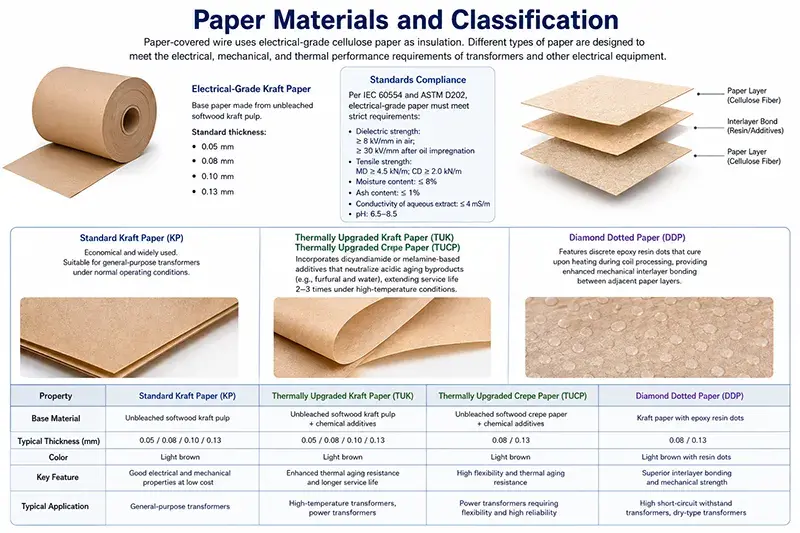
Cable paper is further divided into low density (0.80–0.95 g/cm³, highly permeable, ideal for oil impregnation), medium density (0.95–1.10 g/cm³, versatile), and high density (1.10–1.15 g/cm³, high mechanical strength, suitable for structural roles). These densities differ in dielectric constant (under oil immersion), breakdown strength, mechanical strength, and oil absorption—low‑density paper exhibits high oil absorption (15–20%), making it suitable for high‑voltage main insulation, while high‑density paper absorbs less oil (5–10%) and offers superior mechanical strength, ideal for protective layers. By thickness, cable paper is classified as ultra‑thin (0.05–0.075 mm, mainly used for small low-voltage windings), standard (0.10–0.17 mm, mainly used for medium/high voltage winding turn-to-turn insulation), and thick (0.20–0.25 mm, mainly used for high-voltage winding main insulation end reinforcement).
Thermally upgraded Kraft paper (TUK) modifies cellulose molecular chains using amine compounds (such as dicyandiamide DCD and melamine MA) or amidine compounds (such as cyanoguanidine), raising the thermal class from 105°C (Class A) to 120–130°C (Classes E–B). The core mechanisms of TUK modification include: ① neutralization reactions between amine compounds and acids produced by cellulose hydrolysis (e.g., formic and acetic acids), inhibiting acid‑catalyzed hydrolysis; ② chemical bonding between amidine compounds and cellulose hydroxyl groups, enhancing molecular chain stability; ③ certain modifiers acting as free radical scavengers at elevated temperatures, suppressing oxidative degradation. As a result, TUK paper’s allowable operating temperature increases by 15–25°C, and its service life at the same temperature is extended by a factor of 1.5–2.
Newer paper‑based materials include: ① Nomex T410 (aromatic polyamide paper, DuPont, density 0.45–0.85 g/cm³, thickness 0.05–0.76 mm, temperature rating 220°C, Class C insulation, mainly used for dry-type transformers, and Class H oil-immersed transformers); ② Nomex 410 + Kapton CR composite (PI film plus aramid paper, mainly used for 1100 kV transformer end insulation); ③ TUK + Nomex composite (TUK for oil‑immersed insulation segments, Nomex for dry sections or localized high‑temperature zones); ④ ceramic fiber paper / glass fiber paper (withstanding 500–1,000°C but poorly compatible with transformer oil, mainly used for special dry-type transformers). These new materials, combined with traditional cable paper, constitute a comprehensive “paper insulation material system” covering the full temperature range from Class A to Class C.
Types and Specification System of Paper Covered Wire
Paper‑wrapped wire is classified by conductor shape into round paper‑wrapped wire (diameter 1.00–8.00 mm, mainly used for small/medium capacity low-voltage) and flat paper‑wrapped wire (a = 0.80–6.00 mm × b = 2.00–16.00 mm, mainstream for large-capacity high-voltage,, accounting for over 90% market share); by number of insulation layers into single‑layer (≤1 kV), double‑layer (3–10 kV), multi‑layer (35–110 kV), reinforced insulation (220 kV+), and main insulation (500–1,000 kV, insulation thickness 5–13 mm); by application scenario into eight major categories: power, distribution, HVDC, electric furnace, rectifier, traction, wind & photovoltaic, and nuclear (voltage levels 35 kV–1,000 kV, capacity 10 kVA–1,500 MVA); and by conductor material into copper‑cored (mainstream >90%), aluminum‑cored, Copper Clad Aluminum (CCA), tin‑ or silver‑plated, and enamel‑plus‑paper composites.
Manufacturing Process and Quality Control of Paper Covered Wire
The manufacturing process for paper‑wrapped wire comprises the following steps: conductor finishing → annealing (soft state at 600–700°C / hard state at 350–450°C) → surface cleaning → surface roughening (Ra 0.5–1.6 μm) → tape wrapping (semi‑overlap at 50% or quarter‑overlap at 25%, tension 10–30 N/cm, speed 10–50 m/min) → vacuum drying (80–100°C, 50–100 Pa, 24–48 hours) → vacuum pressure oil impregnation (VPI, 60–80°C, 1–3 kPa, 12–24 hours) → coiling → factory inspection. Key process parameters include: ① wrapping tension (10–30 N/cm); ② overlap ratio (semi‑overlap corresponds to double‑layer thickness); ③ wrapping angle (80–85° relative to the axis); ④ joint beveling (≥20 mm); ⑤ post‑VPI moisture content ≤0.3%, oil impregnation rate ≥95%, and dielectric strength ≥30 kV/mm (in oil). Quality control encompasses incoming raw material inspection, in‑process sampling (≥10%), final inspection (100%), type testing (IEC 60851‑3/5/6 for thermal aging, dielectric, mechanical, and thermal shock resistance), and special tests (short circuit, oil immersion cycling, high/low temperature, and damp heat). High‑end paper‑wrapped wire for 500 kV transformers employs dual‑head wrapping machines to wind inner and outer layers simultaneously, increasing efficiency by 50% and ensuring more uniform overlap.
Dielectric Mechanism of Oil‑Paper Synergistic Insulation
Oil‑paper synergistic insulation is the key performance amplifier of paper‑wrapped wire within the iron‑cored coil. Cellulose paper has a dielectric constant εᵣ ≈ 4.0–4.5 (dry state) / 6.0–8.0 (oil‑immersed state), while transformer oil exhibits εᵣ ≈ 2.2–2.4. This disparity in dielectric constants causes the electric field to concentrate preferentially in the oil gaps, necessitating that paper‑wrapped wire designs establish a continuous, dense paper insulation barrier on the conductor surface to prevent direct exposure of oil gaps to high electric fields.
Transformer oils are classified into four main types: mineral oils (paraffinic, cycloparaffinic, aromatic), synthetic esters (Midel 7131), natural esters (FR3 / Envirotemp 1200, soybean or rapeseed oil‑based), and silicone oils. Mineral oil remains the dominant medium, with breakdown voltage ≥30 kV/2.5 mm, tan δ ≤0.005 (at 90°C), flash point 135–160°C, and kinematic viscosity 9–12 cSt (at 40°C). Natural and synthetic esters have flash points ≥250°C and ignition points ≥300°C,mainly used for indoor substations, rail transit traction transformers, offshore platforms, and other fire-safety-critical applications. The dielectric strength of the oil‑paper synergy is influenced by factors such as moisture, temperature, pressure, and impurities: each 1% increase in moisture content (of the paper) reduces dielectric strength by 8–15%; every 10°C rise in temperature lowers it by 5–8%; and every 100 kPa increase in pressure boosts it by 3–5%.
The Decisive Influence of Core Window Geometry on Paper‑Wound Winding Design
The geometric dimensions of the core window are the most stringent external constraint in the design of paper‑wound core‑wound coils. For a typical three‑phase, three‑limb core, the window height H_w is determined by the total winding height plus the upper and lower end insulation collars (30–80 mm each) and the pressure plates (20–40 mm per limb); for conventional 110 kV transformers, H_w = 1,500–2,000 mm; for 220 kV, 2,000–3,000 mm; for 500 kV, 3,500–5,000 mm; and for 1,000 kV, 5,500–7,500 mm. The window width W_w is set by summing the outer diameters of the individual windings: HV main insulation, inter‑section oil ducts, LV paper‑wound conductor thickness, spacer bar clearances, core limb diameter, and core limb shielding; typical values are W_w = 400–600 mm for 110 kV, 500–800 mm for 220 kV, 800–1,200 mm for 500 kV, and 1,200–1,600 mm for 1,000 kV. The center‑to‑center distance between core limbs, M0 = core limb diameter + window width + clearance to adjacent limbs, is a key parameter that governs the average turn length and the overall outer diameter of the winding.
Subject to the constraints imposed by H_w and W_w, the selection of conductor geometry and the determination of winding layer count must satisfy a system of coupled equations: ① the winding reactance X% is positively correlated with the product of R_m, H_m, and the HV/LV thickness ratio; ② the winding hot‑spot temperature rise θ_h = θ_oil_top + Δθ_oil_top + Δθ_winding_oil + Δθ_winding_oil_top governs insulation life, with the Arrhenius model log₁₀ L = A + B/T establishing an inverse temperature–life relationship (every 6–8°C increase halves the life expectancy); ③ the inter‑disc oil duct width (4–8 mm), together with the paper‑wound layer configuration, determines the insulation thickness—35 kV: 0.50–0.80 mm per side; 110 kV: 1.20–1.80 mm; 220 kV: 2.50–3.50 mm; 500 kV: 5.00–8.00 mm; and 1,000 kV: 9.00–13.00 mm.
The core cross‑sectional area A_Fe multiplied by the voltage per turn e_t determines the total number of turns N = U_phase / e_t. At 50 Hz, typical values of e_t are: 110 kV, 30–50 V/turn; 220 kV, 60–90 V/turn; 500 kV, 100–180 V/turn; and 1,000 kV, 200–300 V/turn. The number of turns N, in turn, dictates the design freedom regarding disc or layer configuration—for example, in a 220 kV, 180 MVA high‑voltage winding with N ≈ 800–1,200 turns, either a disc structure (8–20 turns per disc, totaling 50–100 discs) or a cylindrical structure (tens to hundreds of turns per layer, comprising 4–10 layers) may be employed; the disc arrangement is more suitable for high voltage and large capacity, while the cylindrical layout is preferable for medium and low voltage and smaller capacity.
Design and Manufacturing of Cylindrical Windings with Paper Covered Wire
Cylindrical layer windings are primarily used in distribution transformers rated 35 kV and below, medium‑voltage transformers (10–35 kV), and small‑capacity special‑purpose transformers. The paper‑insulated conductors—typically rectangular or flat wire—are wound axially in multiple layers around the core limbs, with each layer comprising tens to hundreds of turns. Interlayer insulation consists of cable paper (0.10–0.25 mm thick, 2–6 plies) or laminated cardboard (0.50–1.50 mm thick, 1–2 plies). A typical winding has 4–10 layers, with oil ducts 2–4 mm wide between layers for cooling.
Key design considerations: ① The number of turns per layer, N_layer = N_total / n_layer, is evenly distributed to ensure symmetrical impedance; ② The interlayer voltage difference, ΔU_layer = e_t × N_layer, should be limited to 1.5–2.0 times the rated withstand voltage; ③ Electrostatic shields (wrapped with copper or aluminum foil) are installed at the beginning and end of each layer to improve the end‑zone electric field and suppress partial discharge; ④ End‑zone ramps 30–80 mm long with a slope of 5–10% help reduce electric field concentration.
Manufacturing process: Conductor preparation → Paper tape wrapping (half‑lap overlap at 50% or quarter‑lap overlap at 25%, with tension of 10–30 N/cm and a speed of 10–50 m/min) → Vacuum drying (80–100°C, 50–100 Pa, for 24–48 hours) → VPI impregnation (60–80°C, 1–3 kPa, for 12–24 hours) → Winding → End ring assembly → Lead welding → Electrostatic shield installation → Overall compression (0.5–1.5 MPa) → Factory testing.
Advantages: Simple structure, mature technology, large heat‑dissipating surface area, and high insulation reliability. Disadvantages: Nonuniform electric field distribution at the ends, relatively poor short‑circuit strength, and a capacity limit of ≤50 MVA. For applications at 35 kV and below, standardized specifications are provided by IEC 60076‑4, GB/T 1094.4, and IEEE C57.12.00, which set out detailed requirements.
Design and Manufacturing of Disc Windings
Disc windings are the most commonly used configuration in large-capacity oil‑immersed transformers rated 110 kV and above. The basic unit is the “disc” or “pancake”; each disc consists of dozens of turns of rectangular paper‑insulated wire wound radially into a circular shape, with oil ducts (4–8 mm) and inter‑disc insulation (0.50–1.50 mm of layered cable paper) arranged between the discs. There are four sub‑types: Continuous Disc Winding (no joint welding; dominant in 110–500 kV applications; 6–20 turns per disc, 50–100 discs, with an inter‑disc voltage drop of 50–300 V); Interleaved Disc Winding (used in 220 kV and higher to improve lightning impulse distribution; turn‑to‑turn insulation is 20–30% thicker than in continuous windings, with inter‑disc oil ducts of 6–10 mm); Helical Winding (for low‑voltage, high‑current windings below 35 kV, carrying currents from several thousand to tens of kiloamperes; each disc comprises 4–30 parallel strands wound in a single helical turn, often paired with CTC transposed conductors—5–80 enameled flat wires that alternate positions, with an outer layer of paper‑insulated wire); and Inter‑shield Disc Winding (a high‑end solution for 500 kV and above, featuring shielding copper wires or foils inserted between discs to optimize the end‑zone electric field and suppress partial discharge).
The manufacturing process employs automatic winding machines to build the windings disc by disc, starting from the inside and progressing outward. Adjacent discs are joined by transposition joints to ensure continuity of the current path, while turn‑to‑turn insulation is achieved through semi‑lapping wrapping with cable paper (two layers, each 0.10–0.25 mm thick). Advantages include: ① strong resistance to short‑circuit electromagnetic forces (due to uniform radial stress); ② optimized electric field distribution; ③ a capacity limit of 1,500 MVA; and ④ an AC voltage rating up to 1,000 kV. Disadvantages are: ① the process is complex and requires dedicated automatic winding equipment; ② the numerous inter‑disc oil ducts increase manufacturing time; and ③ on‑site maintenance is challenging.
Coordinated Design of Winding Reactance, Leakage Flux, and Short-Circuit Electromagnetic Forces
Winding reactance determines the percentage impedance voltage X% and the short-circuit current level I_sc = I_N / X%. For oil‑immersed transformers, X% typically ranges from 6% to 12% (4%–6% for small and medium units, 8%–12% for medium and large units, and 12%–18% for extra‑large units). The calculation is based on the Rogowski coefficient (K_R ≈ 0.90–0.95) and the winding geometry: X% = 2πf·μ₀·N²·A_leakage·K_R / (H_m·U_N²), where A leakage = π·D_R_m·a·(b + a)/3 (D_R_m is the mean diameter, a is the thickness, b is the reactance height, and H_m is the reactance height). Leakage flux gives rise to three adverse effects: ① additional eddy‑current losses (accounting for 5%–15% of total losses); ② localized overheating of metallic structural components (hotspot temperature rises of 80–120 K in clamps, yokes, and core‑clamping plates); and ③ noise and vibration (60–80 dB(A)). Mitigation strategies involve a combination of paper‑wrapped conductor insulation and electromagnetic shielding—namely aluminum shielding (5–10 mm thick aluminum sheets acting as eddy‑current barriers), magnetic shunts (stacked silicon steel laminations to divert flux), and copper shielding (copper foil to optimize the end‑region electric field)—to ensure that hotspot temperature rises in metallic components do not exceed 80 K (the limit specified in IEC 60076‑7).
The short‑circuit electromagnetic force is given by F = μ₀·N²·i_sc²·A_leakage / (4π·H_m²) and is proportional to the square of the current (i_sc ≈ 12–25 times the rated current). Radial forces range from 50 to 500 kN/m, while axial forces range from 100 to 1,000 kN. Short‑circuit withstand capability is ensured through the overall mechanical strength provided by paper‑wrapped conductors and a tightly clamped structure (with clamping pressures of 0.5–1.5 MPa). Specific test requirements are specified in IEC 60076‑5, IEEE C57.12.00, and GB/T 1094.5.
Coupled Optimization of Temperature Rise, Cooling, and Insulation Life
The temperature rise of the core–coil assembly is the primary determinant of insulation life. In oil-immersed transformers, the hot-spot temperature rise comprises four components: ① top-oil temperature rise (ONAN 35–45 K, ONAF 40–50 K, OFAF 45–55 K); ② average-oil temperature rise (60–70% of the top‑oil rise); ③ winding‑to‑oil mean temperature rise (disc-type 15–25 K, cylindrical-type 20–30 K); ④ hot‑spot‑to‑mean‑winding temperature rise (disc-type 5–15 K, cylindrical-type 10–20 K). Overall, the hot‑spot temperature in oil‑immersed units ranges from 95 to 110°C (Class A/E/B), while in dry-type units it ranges from 120 to 155°C (Class F/H).
Cooling methods are classified as ONAN/ONAF/OFAF/ODAF/ODWF (for oil‑immersed) and AN/AF/ANF (for dry-type). In disc-type windings cooled by OFAF/ODAF, the oil flow velocity in the inter‑disc channels (4–8 mm wide) is 0.5–1.5 m/s, keeping the hot‑spot temperature rise below 10 K; for cylindrical windings, the inter‑layer oil channels (2–4 mm wide) maintain a hot‑spot rise of 15–20 K.
The Arrhenius model (IEC 60076‑7 / IEEE C57.91) expresses an inverse relationship: log₁₀ L = A + B/T—every 6–8°C increase halves the service life (Montsinger empirical rule). For Class A oil‑paper insulation, the reference life at 20°C is 65 years; at 110°C it drops to approximately 7.3 years, and at 98°C to about 18.4 years. TUK‑modified paper suppresses acid‑catalyzed hydrolysis, reducing cellulose degradation by 50–70% and extending life by a factor of 1.5–2. Moisture management is critical: for every 1% increase in paper moisture content, the cellulose degradation rate accelerates by a factor of ten. Typical paper moisture content should be ≤0.5% (in service <1.5%), and oil moisture content ≤5–20 ppm. An integrated multi‑dimensional monitoring system is required, including online moisture monitoring, dissolved‑gas analysis (DGA), partial‑discharge monitoring, and fiber‑optic temperature measurement.
Co‑Design of Core–Winding Local Overheating Mitigation and Magnetic Shielding
The core–winding system experiences local overheating due to three primary mechanisms: ① eddy currents induced by leakage flux in metallic structural components (pressure plates: 5–20 kW, clamps: 3–10 kW, tank walls: 10–50 kW); ② magnetic flux short-circuiting through core tie plates (local temperature rises of 80–150 K); and ③ nonuniform flux distribution at stepped core joints. Magnetic shielding is implemented in three forms: ① aluminum plate shielding (5–10 mm thick, acting as an eddy‑current barrier, reducing pressure‑plate temperature rises by 60–80% and clamp temperature rises by 40–60%, though the aluminum itself incurs 2–5 kW of eddy‑current losses); ② silicon‑steel shunts (30–80 mm thick, diverting leakage flux and reducing pressure‑plate temperature rises by 40–60%, but unsuitable for frequencies above 100 Hz); and ③ copper shielding (0.5–2.0 mm copper foil, combined with paper insulation to improve end‑region electric fields).
Key considerations for the co‑design of magnetic shielding with paper‑insulated windings include: ① interposing a 3–5 mm thick laminated cardboard layer with oil ducts between aluminum shields and windings to ensure electrical insulation; ② insulating silicon‑steel shunts from core clamps via insulated bolts to prevent shorted turns; ③ fully wrapping copper shields with corrugated paper or laminated cardboard to ensure uniform end‑region electric fields; and ④ reliably fixing shielding structures to withstand short‑circuit electromagnetic forces. Seismic design (IEEE 693 / IEC 60068‑3‑3 / GB/T 13540) requires integrated seismic analysis of the core–winding–tank assembly, increasing winding clamping force to 1.0–2.0 MPa, incorporating shock‑absorbing rubber pads and seismic supports, and validating the design through standard seismic tests at acceleration levels of 0.3g, 0.5g, and 1.0g.
Complete Standards System and Test Methods
The application of paper‑wrapped wire in core‑type coils involves six major categories of standards: conductors, insulating paper, transformer oil, paper‑wrapped wire, core‑type coils, and finished transformers.
Conductor Standards: ASTM B49/B193/B279, GB/T 3953/5584, IEC 60028, JIS C 3101/3102. Insulating Paper Standards: IEC 60554‑2/-3/-4, IEC 60641, ASTM D734/D202, GB/T 7969/19264, DIN 7733/46453. Transformer Oil Standards: IEC 60296/61099/62770, ASTM D3487/D6871, IEEE C57.147, GB/T 2536/7595. Core‑Type Coil/Finished Transformer Standards: IEC 60076 series, IEEE C57.12.00/12.91/91/104, GB/T 1094 series, GB/T 6451, TB/T 3230, IEEE 693/4/1, IEC 60172/60851/60270/60085, ASTM D2307.
Core Test Methods (12 items): ① Insulation resistance (≥1,000 MΩ per phase); ② tan δ (at 90°C ≤0.005); ③ AC withstand voltage test for 1 minute; ④ Lightning impulse (1.2/50 μs) + switching impulse (250/2,500 μs); ⑤ Polarity reversal (HVDC); ⑥ Partial discharge (PDIV ≥1.5 times the operating voltage); ⑦ Furfural content (≤0.1 mg/L); ⑧ Oil chromatography (DGA); ⑨ Temperature rise test; ⑩ Noise measurement (IEC 60076‑10); ⑪ Short‑circuit withstand test (IEC 60076‑5); ⑫ Seismic test (IEEE 693).
Selection Decision Matrix and Future Development Trends
The selection of paper‑wound windings requires a comprehensive evaluation across 12 dimensions: voltage and capacity (35 kV–1000 kV, 10 kVA–1500 MVA); insulation class (A/E/B/F/H + TUK); cooling method (ONAN/ONAF/OFAF/ODAF/ODWF); impedance voltage (X% 6–12%); load characteristics; environmental conditions (indoor/outdoor/coastal/high‑altitude/earthquake intensity); fire‑safety requirements (mineral oil/natural ester/dry type); design life (25/30/40/60 years); short‑circuit withstand capability (12–25 times rated current); noise levels (IEC 60076‑10); seismic resistance (IEEE 693—high/middle/low); and maintenance convenience (online monitoring/state‑based maintenance).
Typical Selection Decision Matrix: 35 kV distribution → cylindrical winding + Class A cable paper + mineral oil ONAN; 110 kV medium voltage → cylindrical or disc winding + Class A cable paper + mineral oil ONAN/ONAF; 220 kV high voltage → continuous disc winding + Class A cable paper + mineral oil ONAF; 500 kV extra high voltage → continuous/disc winding with interlaced layers + Class A/B cable paper with TUK + mineral oil OFAF/ODAF; ±800 kV HVDC → continuous disc winding/internal shielding + polarity‑reversal‑resistant insulation + mineral oil ODAF; for electric furnaces/rectifiers → helical winding + Class A cable paper + mineral or natural ester OFAF/ODWF; traction 27.5 kV → cylindrical/disc winding + mineral/synthetic ester ONAN; nuclear power 60 years → continuous disc winding + Class F/H TUK + mineral/synthetic ester ONAF; offshore wind power → cylindrical/disc winding + Class F/H TUK + natural ester ONAF; dry‑type distribution → cylindrical/disc winding + Nomex 410 + AN/AF.
Future Development Trends in six areas: ① High‑temperature heat‑resistant paper wrapping—combining TUK with synthetic esters (Midel 7131/FR3) enables designs with hot‑spot temperatures of 130–140°C, increasing power density by 15–25%; ② Digitalization and intelligence—embedded fiber‑optic temperature sensing, online PD monitoring, and online DGA enable real‑time assessment of winding health; ③ Environmental protection and sustainability—natural esters replacing mineral oil reduce the carbon footprint by 30–50% and ensure 100% biodegradability upon decommissioning; ④ Ultra‑high voltage expansion—applications in 1000 kV UHV AC and ±1100 kV UHV DC drive the iterative development of insulation design and lifetime modeling under DC bias electric fields; ⑤ Novel composite insulation—multi‑layer structures combining paper, PI film (Kapton CR), and aramid paper (Nomex 410) are applied to 1100 kV AC systems and extreme operating conditions; ⑥ Coordinated optimization of magnetic shielding—shielding schemes integrating aluminum plates, silicon steel, and copper, based on multiphysics coupling simulations, reduce localized overheating in metallic components by 30–50%.
In summary, paper‑wound windings, as the core insulation solution for transformer core‑coil design, have evolved from a simple “conductor + insulation” binary structure into a full‑system technical framework encompassing conductors, insulating papers, transformer oils, winding configurations, core window geometry, leakage flux and short‑circuit forces, magnetic shielding, temperature rise and cooling, and monitoring and maintenance. Design engineers must adopt a systematic approach across multiple dimensions—conductor materials, types of insulating paper, winding configurations, drying and oil impregnation processes, liquid media, and magnetic shielding strategies—to ensure the safe and reliable operation of transformers over their 30–60 year service life.
Reference Standards and Documents
[1] IEC 60076-1: Power Transformers – Part 1: General; [2] IEC 60076-2: Temperature Rise; [3] IEC 60076-3: Insulation Levels and Dielectric Tests; [4] IEC 60076-4: Guide to Lightning Impulse and Switching Impulse Testing; [5] IEC 60076-5: Ability to Withstand Short Circuit; [6] IEC 60076-7: Loading Guide for Oil-Immersed Power Transformers; [7] IEC 60076-10: Determination of Sound Levels; [8] IEC 60076-11: Dry-Type Transformers; [9] IEC 60270: Partial Discharge Measurements; [10] IEC 60172: Interturn Insulation Test; [11] IEC 60851: Winding Wire Test Methods Series; [12] IEC 60085: Thermal Classification of Electrical Insulation; [13] IEEE C57.12.00: General Requirements for Liquid-Immersed Distribution, Power, and Regulating Transformers; [14] IEEE C57.12.91: Short-Circuit Withstand Capability Test; [15] IEEE C57.91: Loading Guide; [16] IEEE C57.104: Guide for Detection of Acoustic and Electromagnetic Emissions from Partial Discharges; [17] IEEE 693: Seismic Design of Substations; [18] IEEE 4 / IEEE 1: Dielectric Measurement Standards; [19] ASTM B49 / B193 / B279; [20] ASTM D734 / D202 / D2307 / D3487 / D6871 / D5837; [21] GB/T 1094 Series; [22] GB/T 6451; [23] GB/T 7969 / 19264 / 3953 / 5584 / 2536 / 7595; [24] TB/T 3230; [25] DIN 7733 / 46453; [26] JIS C 3101 / 3102; [27] IEC 60554-2/-3/-4; [28] IEC 60641; [29] IEC 60296 / 61099 / 62770; [30] IEC 62271 / 60068-3-3; [31] ISO 9001 / 14001 / 45001.