


Conductor Materials and Geometric Configurations of Paper‑Insulated Winding
The conductor material for paper‑insulated windings is predominantly high‑purity electrolytic copper (C11000 ETP), with key control parameters including a copper content ≥99.90%, an oxygen content ≤0.04%, a volume resistivity ≤0.01724 Ω·mm²/m (20°C), an IACS conductivity ≥100%, an elongation (soft state) ≥35%, and a tensile strength of 200–250 MPa. A small proportion of aluminum conductors (C1350‑O / 6101‑T81) are used in cost‑ or weight‑sensitive transmission and distribution applications, but their share remains far lower than that of copper conductors. The conductor geometry is mainly rectangular (flat wire) and square; round paper‑insulated conductors appear only in low‑capacity distribution transformers or specialized designs.
For rectangular conductors, the thickness (a) typically ranges from 0.80 to 6.00 mm, and the width (b) from 2.00 to 16.00 mm, with rounded corners having a radius r ≥0.5 mm and r ≥a/10 to prevent stress concentration and electric field distortion. The width‑to‑thickness ratio b/a is generally maintained between 2.5 and 8.0; too narrow a ratio reduces the efficiency of paper tape winding, while too wide a ratio can lead to wrinkling and loosening of the tape after bending and shaping. In ultra‑high‑voltage power transformers of 500 kV and above, conductor widths may reach 14–16 mm; in the valve‑side windings of HVDC converter transformers, single‑conductor thicknesses are constrained by the skin effect, and thin flat wires of 1.0–2.5 mm with transposition arrangements are commonly employed. The surface roughness Ra of the conductor should be controlled within the range of 0.5–1.6 μm to facilitate tight tape adherence and oil impregnation.
Insulating Paper Material Systems and Hierarchical Structure
The primary insulating material in paper‑wrapped conductors is cellulose‑based insulating paper, which is classified into three types according to its application: cable paper (Kraft Paper), transformer turn‑to‑turn paper (Crepe Paper/Corrugated Paper), and laminated pressboard (Pressboard/Transformer board). Cable paper is manufactured from unbleached sulfate wood pulp and is available in eight thickness grades: 0.05 mm, 0.075 mm, 0.10 mm, 0.125 mm, 0.17 mm, 0.20 mm, and 0.25 mm; its density ranges from 0.80 to 1.15 g/cm³; the longitudinal tensile strength is ≥6.5 kN/m for the 0.10‑mm grade; and the electrical breakdown strength in air is ≥8 kV/mm, increasing to ≥30 kV/mm after oil impregnation under an oil‑filled gap.
Corrugated paper is produced by mechanically creping cable paper. Common thicknesses are 0.10 mm, 0.12 mm, and 0.17 mm (as‑received), with effective thicknesses of 0.25–0.45 mm after stretching. It is primarily used for rounding conductor corners, end insulation, and wrapping irregular shapes, providing mechanical cushioning and maintaining oil‑flow channels.
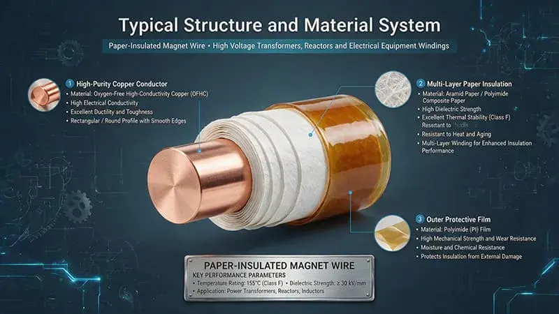
Thermally Upgraded Kraft Paper (TUK) is a high‑heat‑resistant paper developed since the 1970s to address the rising hot‑spot temperatures in oil‑immersed transformers. By chemically modifying cellulose through the addition of amine compounds (such as dicyandiamide and melamine) or amidine compounds, it effectively suppresses acid‑catalyzed hydrolysis at elevated temperatures, reducing the cellulose degradation rate by 50%–70%. The thermal class of TUK paper has been upgraded from 105°C (Class A) for conventional cable paper to 120°C–130°C (Classes E–B), allowing transformer design hot spots to be increased from 98°C to 110°C–120°C, thereby enhancing overload capacity or extending service life. Laminated pressboard is divided into low‑density grades (0.95–1.15 g/cm³) and high‑density grades (1.20–1.35 g/cm³), with thicknesses ranging from 1.0 to 8.0 mm, and is mainly used for structural support components such as winding end rings, partitions, spacers, and pressure plates.
Paper tape winding methods are categorized according to insulation layer requirements as follows: half‑lap winding (50% overlap), double half‑lap winding (two layers with 50% overlap), quarter‑lap winding (25% overlap), and flat winding (gapless, continuous wrap). Typically, a single layer of insulation is 0.10–0.20 mm thick; double half‑lap winding provides 0.20–0.40 mm; and three layers offer 0.30–0.60 mm. Winding speeds range from 10 to 50 m/min, with tension controlled within ±10% to ensure tight, wrinkle‑free, bubble‑free wrapping. Following winding, the conductor must undergo vacuum drying (80–100°C, 50–100 Pa, 24–48 hours) and vacuum pressure oil impregnation (60–80°C, 1–3 kPa, 12–24 hours) to fully saturate the insulating paper with transformer oil and eliminate internal air gaps.
The Synergistic Oil–Paper Insulation System
The insulation performance of paper‑wrapped conductors depends not only on the paper itself but, more importantly, on the “paper + oil” synergistic system. Oil–paper insulation is the classic insulation paradigm for windings in oil‑immersed transformers. Its typical dielectric constants are: cellulose paper εᵣ ≈ 4.0–4.5 (dry state) / 6.0–8.0 (oil‑impregnated state), and transformer oil εᵣ ≈ 2.2–2.4. The difference in their dielectric constants causes the electric field to concentrate preferentially in the oil gaps; therefore, the core of paper‑wrapped conductor design is to form a continuous, dense paper insulation barrier on the conductor surface, preventing the oil gaps from directly bearing high electric fields.
Transformer oils are classified chemically into three types: mineral oil (naphthenic, paraffinic, and aromatic), synthetic ester (e.g., Midel 7131), natural ester (e.g., FR3 / Envirotemp 1200), and silicone oil. Mineral oil remains the dominant medium due to its excellent electrical properties (breakdown voltage ≥30 kV/2.5 mm, tan δ ≤0.005 at 90°C), low cost, and well‑established application experience. It has a flash point of 135–160°C, a fire point of 165–185°C, and a kinematic viscosity of 9–12 cSt at 40°C. Natural and synthetic esters have flash points ≥250°C and fire points ≥300°C, offering significantly superior fire‑resistance performance compared to mineral oil, and are primarily used in indoor substations, traction substations for rail transit, offshore platforms, and other applications with stringent fire‑safety requirements. Silicone oil is employed in extreme conditions—either very low temperatures (for starting below −60°C) or very high temperatures (above 200°C).
Moisture is the primary adversary of oil–paper insulation. In the dry state, the moisture content of the insulating paper should be ≤0.5% (by mass); during operation, it must be kept below 1.5%. In transformer oil, the water content should be ≤20 ppm for systems of 66 kV and below, ≤15 ppm for 110 kV, ≤10 ppm for 220 kV, ≤8 ppm for 500 kV, and ≤5 ppm for ultra‑high‑voltage systems. Under the influence of an electric field, moisture can trigger interfacial discharges at the oil–paper boundary, accelerate cellulose hydrolysis (with each 1% increase in moisture content, the rate of cellulose degradation increases by approximately tenfold), and substantially reduce both insulation resistance and breakdown voltage.
Design Requirements and Insulation Challenges of Heavy‑Duty Transformers
During operation, the windings of heavy‑duty transformers are subjected to the superposition of four types of stresses: electrical, thermal, mechanical, and environmental. Electrical stress comprises power‑frequency voltage (under continuous operation), lightning impulse (BIL, Basic Insulation Level), switching impulse (SI, Switching Impulse), and polarity reversal (applicable only to HVDC converter transformers). For 500 kV transformers, the typical BIL is 1,550 kV; it increases to 1,950 kV for 750 kV systems and reaches 2,400 kV for 1,000 kV systems. The corresponding switching impulse withstand levels are 1,175 kV (500 kV), 1,550 kV (750 kV), and 1,800 kV (1,000 kV). HVDC converter transformers experience the combined action of DC and AC voltages; under a DC bias electric field, the resistive shunt effect in oil–paper insulation becomes significant, and the accumulation of space charge in the paper can distort the electric field, reducing the partial discharge inception voltage (PDIV) by 20%–40%.
Regarding thermal stress, the design‑specified hot‑spot temperatures for heavy‑duty transformers are as follows: for oil‑immersed transformers with Class A insulation, 95°C; for Class E, 105°C; and for Class B, 110°C. Current mainstream designs adhere to IEC 60076‑7 and IEEE C57.91, which specify load guidelines for oil‑immersed transformers, with hot‑spot temperature limits of 110°C (ONAN, normal oil natural circulation), 120°C (ONAF), 130°C (OFAF, forced oil circulation), and 140°C (ODAF, forced directed oil circulation). According to Montsinger’s rule of thumb, corresponding to an Arrhenius activation energy of 0.7–1.0 eV, every 6–8°C rise in hot‑spot temperature halves the insulation life.
Mechanical stress primarily arises from short‑circuit electromagnetic forces acting on the windings—radial compressive forces and axial tensile forces—which are proportional to the square of the short‑circuit current, reaching peak values 12–25 times the normal operating current. Seismic loads (per IEEE 693 and IEC 60068‑3‑3), transport vibrations, and platform motion on offshore installations impose additional requirements on winding mechanical integrity. Environmental stress encompasses temperature cycling, humidity, lightning overvoltages, pollution, and coastal salt spray, among others.
Paper‑Wrapped Wire in Major Heavy‑Duty Transformer Applications
Power Transformers (35 kV–1000 kV): Paper‑wrapped wire serves as the core of the winding’s main insulation, supplemented by turn‑to‑turn insulation (paper thickness 0.10–0.25 mm), layer‑to‑layer insulation (0.50–2.00 mm laminated cardboard), and end‑winding insulation (creped paper + molded components). For main transformers of 500 kV and above, transposed conductors (CTC, Continuously Transposed Conductor) are commonly used to suppress eddy‑current losses. A CTC consists of 5–80 strands of enameled flat wire arranged in a transposed configuration, wrapped with paper insulation, and cured in epoxy; individual strand thickness is 1.0–3.0 mm, and the cross‑sectional area of a single CTC ranges from 30 to 200 mm².
HVDC Converter Transformers: Both the grid‑side and valve‑side windings employ paper‑wrapped flat conductors. The valve side experiences combined DC and AC voltages, so the insulation margin is increased by 20%–30%. Typical designs include 0.5–2 layers of 0.10 mm cable paper plus 0.5–1 layer of 0.125 mm high‑density laminated paper, impregnated with mineral oil of high dielectric strength (breakdown voltage ≥70 kV/2.5 mm). HVDC polarity reversal tests (±DC for 90 minutes each, in alternating cycles) verify the stability of space charge at the paper‑oil interface.
Electric Furnace Transformers: In high‑current, low‑voltage applications such as electric arc furnaces (EAF), ladle furnaces (LF), and submerged arc furnaces, currents can reach 10–80 kA. These transformers typically use large‑cross‑section paper‑wrapped flat conductors (30–100 mm² per strand) or transposed conductors, equipped with forced oil circulation cooling (OFAF or ODWF). Frequent short‑circuit stresses necessitate insulation with outstanding mechanical stability.
Rectifier Transformers: In high‑power rectification applications—such as aluminum electrolysis (Al), zinc electrolysis (Zn), copper electrolysis (Cu), electroplating, and ECM—secondary DC currents may range from 100 to 400 kA. Windings employ thick paper wrapping around rectangular conductors (a = 4–8 mm, b = 10–20 mm), with multi‑path water‑or oil‑cooled winding configurations, impregnated with high‑flashpoint mineral oil or natural esters to meet fire‑safety requirements.
Traction Transformers (27.5 kV / 55 kV Overhead Lines): Used in railway, urban rail, and subway traction substations, these transformers endure frequent overloads (up to 2–3 times rated capacity), harmonic currents, and vibration impacts. They feature Class A/B paper‑wrapped wire designs, with windings comprising 2–4 layers of 0.10–0.17 mm cable paper and 0.50 mm creped paper at the ends, all impregnated with mineral oil.
Wind and Photovoltaic Step‑Up Transformers: Onshore wind power applications include 0.69/35 kV, 3.3/66 kV, and 6.6/66 kV step‑up package substations; offshore wind facilities utilize 66/220 kV step‑up main transformers on platforms; photovoltaic systems employ 0.8/35 kV integrated inverter‑step‑up units. These transformers adopt Class B/F paper‑wrapped wire designs, emphasizing resistance to harmonics and vibration, as well as long service life (25–30 years).
Nuclear Power Plant Auxiliary Transformers: Including main transformers for the conventional island (CON), start‑up transformers for emergency diesel generators (EDG), and auxiliary service transformers (ASU), these units are certified to safety classes according to IEEE 323, IEEE 344, and IEEE 383 standards. They employ Class F/H paper‑wrapped wire designs with a 60‑year design life.
Aging Mechanisms and Lifetime Assessment
Oil–paper insulation aging is the result of the long-term, synergistic effects of electrical, thermal, mechanical, and environmental stresses. The cellulose degradation mechanisms include hydrolysis‑dominated main‑chain scission, pyrolysis‑induced side‑chain cleavage, and oxidation‑driven glucose ring opening; these processes act in concert, causing the degree of polymerization (DP) to decline gradually from an initial value of 1,000–1,200 to approximately 200–250 at end of life. Furfural (2‑FAL), as a degradation marker, dissolves in transformer oil, and its concentration measurement is an internationally recognized method for assessing insulation aging: <0.1 mg/L indicates normal conditions, 0.1–0.5 mg/L denotes mild aging, 0.5–1.0 mg/L corresponds to moderate aging, 1.0–2.0 mg/L indicates severe aging, and >2.0 mg/L signifies the final stage of life (IEEE C57.104 / IEC 61198 / ASTM D5837).
Oil degradation products include: acid value (expressed as KOH mg/g) rising from ≤0.03 to 0.10–0.30; dielectric loss tangent tan δ (at 90°C) increasing from ≤0.005 to 0.010–0.050; and breakdown voltage decreasing from ≥50 kV/2.5 mm to 30–40 kV/2.5 mm. Polarization at the oil–paper interface and the accumulation of space charge can accelerate dielectric aging of the paper. Lifetime prediction is based on the Arrhenius model (IEC 60076‑7 / IEEE C57.91): log₁₀ L = A + B/T (where L is the lifetime in hours, A and B are constants, and T is the hot‑spot temperature in kelvins). For conventional Class A oil–paper insulation at 20°C, the reference lifetime is 65 years (α = 0.115); for every 6–8°C increase in hot‑spot temperature, the lifetime is halved.
Key Design Parameters and Manufacturing Processes
Key design parameters for paper‑wrapped wire: conductor dimensional tolerances (thickness ±0.02 mm, width ±0.05 mm); conductor surface roughness Ra 0.8–1.6 μm; paper‑tape overlap ratio (≥50% half‑lap / ≥25% quarter‑lap); paper‑tape tension (10–30 N/cm width); winding speed (10–50 m/min); winding angle (helix lead angle 5°–15°, to avoid stress concentration at bends); drying process (vacuum at 100°C / 50 Pa / 24 h + oil impregnation at 60°C / 1 kPa / 12 h). After winding and shaping, the conductor must undergo three‑step pre‑treatment: constant‑pressure drying (90–110°C / 24–48 h), vacuum‑pressure oil impregnation (≤100 Pa / 80°C / 12 h), and static degassing (≥72 h).
Insulation thickness (increment per side) increases with voltage level: 35 kV 0.50–0.80 mm, 110 kV 1.20–1.80 mm, 220 kV 2.50–3.50 mm, 500 kV 5.00–8.00 mm, 750 kV 7.00–11.00 mm, 1000 kV 9.00–13.00 mm. For CTC stranded conductors, inter‑strand paper insulation is 0.10–0.17 mm × 2 layers, plus an overall outer insulation of 0.50–1.00 mm; individual CTC cross‑section ranges from 30 to 200 mm².
Standards System and Quality Verification
Standards related to paper‑enameled wire and oil‑paper insulation cover four levels: conductors, insulating paper, transformer oil, and finished windings:
- Conductor Standards: ASTM B49 (Drawn Round Copper Wire), ASTM B193 (Electrical Resistivity), ASTM B279 (Rectangular Copper Wire), GB/T 3953 (Round Copper Wire for Electrical Purposes), GB/T 5584 (Flat Copper Strips for Electrical Use), IEC 60028 (International Standard for Electrical Resistivity), JIS C 3101 / 3102
- Insulating Paper Standards: IEC 60554‑2 / -3 / -4 series (Cellulose Papers for Electrical Applications), IEC 60641 (Laminated Pressboard), ASTM D734 (Dielectric Properties of Cable Paper), ASTM D202 (Test Methods for Paper), GB/T 7969 (Cable Paper), GB/T 19264 (Laminated Pressboard for Transformers), DIN 7733 / 46453
- Transformer Oil Standards: IEC 60296 (Mineral Transformer Oil), IEC 61099 (Synthetic Ester), IEC 62770 (Natural Ester), ASTM D3487 (Mineral Oil Specifications), ASTM D6871 (Natural Esters), IEEE C57.147 (Guidelines for Natural Esters), GB/T 2536, GB/T 7595
- Finished Transformer Standards: IEC 60076 series (Oil‑Immersed Transformers), IEEE C57.12.00 (General Requirements for Liquid‑Immersed Equipment), C57.12.91 (Short‑Circuit Withstand Capability), C57.91 (Load Guide), C57.104 (Oil‑Paper Aging Monitoring), GB/T 1094, GB/T 6451 (Parameters for Oil‑Immersed Power Transformers), TB/T 3230 (Traction Transformers)
Verification tests for finished windings include: insulation resistance testing (using a 5,000 V megohmmeter, ≥1,000 MΩ per phase); dielectric dissipation factor tan δ (at 90°C, ≤0.005); breakdown voltage (under power‑frequency stress for 1 minute); impulse voltage testing (lightning impulse 1.2/50 μs + switching impulse 250/2,500 μs); polarity reversal (for HVDC applications); partial discharge (PDIV ≥1.5 times the operating voltage, per IEC 60270); furfural content (≤0.1 mg/L); dissolved gas analysis (DGA) of the oil (H₂/CH₄/C₂H₂/C₂H₄/C₂H₆ plus CO/CO₂); temperature rise test; noise measurement; and short‑circuit withstand testing.
Selection, Procurement, and Operations & Maintenance
During the design and selection phase, comprehensive considerations should include: rated voltage and capacity, insulation class (A/E/B/F), cooling method (ONAN/ONAF/OFAF/ODAF), impedance voltage, load characteristics (continuous / cyclic / short-time overload), environmental conditions (indoor / outdoor / coastal / high‑altitude / high‑seismic), fire‑safety requirements (mineral oil / natural ester / dry‑type), expected service life (25 / 30 / 40 / 60 years), and ease of operation and maintenance. Conductor material selection: copper (for high currents / compact designs / long service life) or aluminum (for weight reduction / cost sensitivity / large capacities). For paper insulation: cable paper (standard), corrugated paper (for irregular shapes), TUK (for high temperatures / long life / high overload capability), and laminated cardboard (for structural components).
Procurement verification points: conductor raw‑material testing (resistivity, elongation, tensile strength, chemical composition); paper testing (thickness, density, tensile strength, dielectric breakdown, moisture content); random inspection during winding and wrapping (paper‑tape overlap ratio, tension, appearance); and finished‑product testing (insulation resistance, dielectric loss, dielectric breakdown, PDIV). Third‑party supervision may be carried out by international organizations such as DNV, TÜV, BV, CCS, and SGS.
Operations and maintenance strategy: online monitoring (online DGA + oil temperature + online partial discharge + fiber‑optic winding‑temperature measurement + regular furfural sampling); periodic testing (annual oil chromatography, once every three years for furfural, and once every six years for insulation resistance and dielectric loss); condition‑based maintenance (based on risk assessment); and life extension (oil regeneration / paper insulation replacement / major overhaul of the entire unit).
Future Development Trends
In the future, paper‑wound‑wire technology in heavy‑duty transformer design will exhibit four major trends: First, the widespread adoption of high‑temperature‑resistant papers—the combination of TUK and synthetic esters (Midel 7131 / FR3) enables hot‑spot temperature designs of 130–140°C, increasing transformer power density by 15%–25%; second, digitalization and intelligentization—embedded fiber‑optic temperature sensing, online partial discharge monitoring, and online dissolved gas analysis facilitate real‑time assessment of winding health; third, environmental friendliness and sustainability—natural esters (soybean oil‑ or rapeseed oil‑based FR3) are replacing mineral oil, reducing the carbon footprint by 30%–50% and ensuring 100% biodegradability upon decommissioning; fourth, ultra‑high‑voltage expansion—1,000 kV EHV and ±800 kV/±1,100 kV UHVDC applications are driving iterative advances in insulation design and lifetime modeling for paper‑wound wires under DC bias electric fields; fifth, novel composite insulation—a layered structure comprising paper, PI film (Kapton CR), and aramid paper (Nomex 410) is being applied to higher voltage classes (1,100 kV AC) and extreme operating conditions (polar regions/high altitudes).
In summary, as the core insulation solution for heavy‑duty transformer windings, paper‑wound wire has evolved into a comprehensive system encompassing conductors, insulating papers, transformer oils, winding processes, testing standards, aging assessments, and maintenance practices. Design engineers should, based on voltage level, capacity requirements, insulation class, environmental conditions, expected service life, and budgetary constraints, systematically select appropriate configurations across dimensions such as conductor materials, types of insulating paper, winding layup, drying and oil impregnation processes, and liquid dielectrics, thereby ensuring the safe and reliable operation of transformers throughout their 30–60 year service life.