


Enameled copper wire (also known as magnet wire) is one of the most fundamental and critical components in electrical engineering. Its core value lies not in the enamel coating itself, but in the fact that the enamel coating enables copper conductors to be tightly wound in high-density configurations without causing short circuits—precisely the prerequisite for efficient conversion of electrical energy into magnetic energy. Understanding this requires starting from the physical foundations of magnetism.
Fundamental Physics Behind Magnetism
Magnetism is, at its core, a macroscopic manifestation of electron behavior. To understand the role of copper wire in magnetic fields, one must first understand the origin of magnetism.
Atomic Origin: Electron Spin and Orbital Motion
Magnetism arises from two fundamental types of electron motion: spin and orbital motion. Each electron’s spin generates an intrinsic magnetic moment, oriented either “up” or “down,” as dictated by quantum mechanics. The electron’s orbital motion around the atomic nucleus produces an orbital magnetic moment. These two magnetic moments vectorially sum at the atomic scale to yield the atom’s total magnetic moment.
Macroscopic magnetic differences among elements reflect differences in their electronic structures. Iron (Fe), cobalt (Co), and nickel (Ni) possess unpaired electrons in their 3d electron shells; these unpaired electron spins can align parallel, resulting in strong magnetism. Copper (Cu) has the electron configuration [Ar] 3d¹⁰ 4s¹—the 3d shell is fully filled—meaning copper atoms possess no permanent magnetic moment and are intrinsically nonmagnetic.
Magnetic Moment and Magnetic Domains: Bridging to Macroscopic Magnetism
The magnetic moment of a single atom is extremely small (Bohr magneton μB ≈ 9.274 × 10⁻²⁴ J/T). However, ferromagnetic materials contain a special internal structure—magnetic domains. Within each domain, the magnetic moments of billions of atoms align parallel, producing a strong local magnetization direction.
Adjacent domains are separated by domain walls. In the unmagnetized state, domain magnetization directions are randomly distributed, yielding zero net macroscopic magnetization. Under an applied external magnetic field, domain walls move and domains aligned with the field expand—this process manifests macroscopically as magnetization.
Four Classes of Magnetic Materials
Materials are classified into four categories based on their response to an external magnetic field:
Ferromagnetic: Fe, Co, Ni, and certain rare-earth materials; relative magnetic permeability μr ≫ 1 (typically 100–10,000); capable of permanent magnetization. Iron cores used in magnet wire windings belong to this class.
Paramagnetic: μr slightly greater than 1 (typically 1.0001–1.01); magnetization vanishes almost entirely upon removal of the external field. Aluminum, platinum, and air fall into this category.
Diamagnetic: μr less than 1 (typically ~0.9999); exhibits weak repulsion from magnetic fields. Copper, silver, gold, and bismuth are diamagnetic.
Ferrimagnetic: Ferrite materials (e.g., MnZn and NiZn ferrites) belong to this class. They exhibit high magnetic permeability but extremely low electrical conductivity, making them the preferred choice for high-frequency magnetic cores.
Curie Temperature: The Critical Threshold of Magnetism
The Curie temperature (TC) is the critical point for ferromagnetic materials. Below TC, the material exhibits ferromagnetism; above TC, thermal agitation disrupts the ordered arrangement of magnetic domains, and the material transitions to paramagnetism.
| Material | Curie Temperature |
|---|---|
| Iron (Fe) | 770°C |
| Cobalt (Co) | 1121°C |
| Nickel (Ni) | 354°C |
| MnZn Ferrite | 120–250°C |
Copper itself is nonmagnetic and has no Curie temperature. However, the Curie temperature of the iron core directly limits the maximum operating temperature of transformers.
Why Copper Is the Preferred Conductor for Enameled Wire
Copper is virtually “absent” in the magnetic domain, yet it remains the gold standard conductor for magnet wire. This preference stems from a dual perspective: electrical performance and magnetic behavior.
Electrical Conductivity Advantage: Minimizing Energy Conversion Losses
At 20°C, copper exhibits an electrical resistivity of approximately 1.724×10⁻⁸ Ω·m and an International Annealed Copper Standard (IACS) conductivity of 100%—making it the second-best metallic conductor after silver (silver IACS ≈ 106%).
The core function of enameled wire is to carry current and generate a magnetic field. For a given current, copper wire incurs the lowest I²R loss, meaning more electrical energy is converted into magnetic energy rather than heat.
The Diamagnetic Nature of Copper
Copper is a typical diamagnetic material, with a magnetic susceptibility χ ≈ −9.6×10⁻⁶ (SI units). This implies that copper itself cannot be magnetized and does not perturb external magnetic field distributions. This property is critically important for precision coils—where the coil’s magnetic field is determined solely by the current, free from magnetic interference caused by the conductor material.
In practical engineering, copper wire exhibits no magnetic response in static magnetic fields; however, under alternating magnetic fields, it generates eddy currents (discussed in detail later)—a phenomenon distinct from diamagnetism.
Refining Process for High-Purity Copper
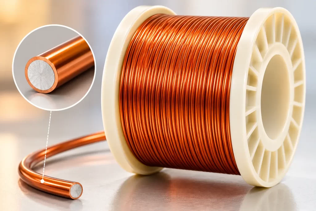
Modern magnet wire employs electrolytically refined copper with purity exceeding 99.99% (4N). C11000 (Electrolytic Tough Pitch Copper, ETP) is the predominant grade.
Advantages of high-purity copper:
- Reduces localized resistivity increases caused by inclusions
- Prevents magnetic hysteresis losses induced by ferromagnetic impurities (e.g., Fe, Ni)
- Enhances ductility after annealing, facilitating fine-wire drawing
Oxygen-Free High-Conductivity Copper (OFHC) achieves purities up to 99.999%, and is used in specialized applications such as hydrogen-cooled motors/generators or vacuum environments.
Critical Role of the Enamel Coating in Magnetic Fields
The enamel coating’s primary function is electrical insulation; however, its presence also subtly influences magnetic field behavior.
Balancing Electrical Insulation and Magnetic Compatibility
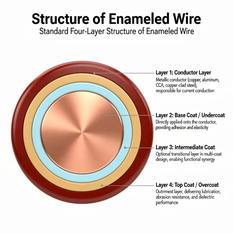
The fundamental requirement for enameled wire is to enable the copper conductor to be wound as tightly as possible (to maximize slot fill factor) while preventing inter-turn short circuits. Enamel coating thickness typically ranges from 0.02–0.06 mm, yet it must withstand breakdown voltages of 1.5–10 kV.
The non-magnetic nature of the enamel coating is a critical design consideration. If the coating contained ferromagnetic fillers, it would disrupt the uniformity of the coil’s magnetic field. Therefore, all commercially available enamel coatings—such as polyurethane, polyester, and polyimide—are either paramagnetic or diamagnetic materials, with magnetic permeability μ closely matching that of air.
Electromagnetic Behavior of Polymer Enamel Coatings
Different enamel coating materials exhibit distinct relative permittivities (εr):
| Enamel Material | Relative Permittivity *ε*r | Dielectric Loss at High Frequencies |
|---|---|---|
| Polyurethane (UEW) | 3.5–4.5 | Medium |
| Polyester (PEW) | 3.0–4.0 | Low |
| Polyesterimide (EIW) | 3.5–4.5 | Low |
| Polyamide-imide (AIW) | 3.5–4.5 | Low |
| Polyimide (PIW) | 3.0–3.5 | Extremely low |
Dielectric loss tangent (tan δ) significantly impacts coil quality factor (Q) at high frequencies (>1 MHz). Polyimide (PI) enamel exhibits the lowest tan δ, making it the preferred choice for high-frequency applications.
Minor Magnetic Field Shielding Effect of Enamel Thickness
The enamel coating is a non-conductor and thus completely transparent to static magnetic fields. However, at high frequencies, capacitive coupling between the enamel and the conductor intensifies the proximity effect. This is not magnetic “shielding” by the enamel, but rather a redistribution of current density. The design objective is not to minimize enamel thickness, but rather to select an appropriate enamel thickness grade (Grade 1/2/3) based on application requirements.
Key Electromagnetic Parameters of Enameled Copper Wire
Engineering selection relies on several core parameters.
Magnetic Permeability (*μ*)
Absolute magnetic permeability μ = B/H, unit: H/m. Vacuum magnetic permeability μ₀ = 4π×10⁻⁷ H/m.
Relative magnetic permeability μᵣ = μ/μ₀:
- Copper: *μ*ᵣ ≈ 0.999994 (diamagnetic)
- Air: *μ*ᵣ ≈ 1.000000
- Iron core (silicon steel): *μ*ᵣ ≈ 500–5000
- MnZn ferrite: *μ*ᵣ ≈ 1000–15000
The enameled wire winding itself contributes no magnetic permeability gain; all permeability enhancement originates from the iron core. The role of enameled wire is to deliver current to the region of highest magnetic field strength with minimal resistance.
Coercivity (*H*c) and Magnetic Hysteresis
Coercivity is the reverse magnetic field strength required to reduce magnetization to zero, unit: A/m. Copper exhibits negligible coercivity (Hc ≈ 0) and shows no hysteresis behavior. Magnetic hysteresis loss occurs exclusively in the core material and is largely unrelated to the enameled wire.
However, rapid current switching in windings (e.g., in switch-mode power supplies or pulsed applications) induces skin effect and proximity effect within the conductor, indirectly influencing the dynamic behavior of the magnetic core.
Electrical Resistivity and Temperature Coefficient
Copper resistivity ρ = 1.724×10⁻⁸ Ω·m at 20°C, temperature coefficient α = 0.00393 /°C. Winding resistance increases with temperature, constituting the primary limiting factor for current density (J, expressed in A/mm²).
Empirical current density guidelines for motor windings:
- Small motors: 6–10 A/mm²
- Medium-to-large motors: 3–6 A/mm²
- High-frequency transformers: 5–15 A/mm²
Excessively high current density elevates I²R loss. When copper temperature rise exceeds the thermal class rating of the enamel coating—Class F (155°C), Class H (180°C), Class N (200°C), or Class R (220°C)—service life declines sharply (halving for every 10°C of excess temperature).
Magnetic Behavior of Enameled Copper Wire at Different Frequencies
The “magnetism” of enameled copper wire is synonymous with the magnetic field generated by current flow. Behavior differs significantly across frequencies.
DC Steady State
Under DC excitation, an enameled copper wire coil produces a static magnetic field, with magnetic flux density B = μ·n·I (n = turns per unit length). Current distributes uniformly across the conductor cross-section; skin effect is absent.
Low-Frequency AC (50/60 Hz)
Skin depth at power frequency:
δ = √(2ρ/(ωμ)) = √(2 × 1.724 × 10⁻⁸ / (2π × 50 × μ₀ × μᵣ)) ≈ 9.3 mm (copper)
This is far greater than typical enameled copper wire diameters (0.1–2 mm); skin effect is negligible.
Medium-to-High Frequency (1 kHz – 1 MHz)
At 100 kHz, the skin depth in copper is approximately 0.21 mm. For AWG 26 wire (diameter 0.4 mm), skin effect becomes pronounced: current concentrates in a thin outer shell of the conductor, reducing utilization of the copper core.
Radio Frequency (>1 MHz)
At 13.56 MHz, skin depth drops to only 0.018 mm. The effective cross-sectional area of the solid conductor in standard enameled copper wire decreases sharply, causing a substantial rise in equivalent resistance. This is precisely the core problem addressed by Litz wire.
Skin Effect and Proximity Effect
These are two fundamental challenges that enameled copper wire must address in high-frequency applications.
Skin Depth Formula
δ = √(2ρ/(ωμ))
where:
- ρ: electrical resistivity
- ω: angular frequency (ω = 2πf)
- μ: magnetic permeability (μ = μ₀μᵣ)
At 100 kHz, the skin depth δ for copper is approximately 0.21 mm (μᵣ ≈ 1).
Proximity Effect
The proximity effect is a current distribution distortion caused by magnetic field superposition between adjacent conductors in multi-turn windings. When two current-carrying conductors are placed in close proximity, current tends to concentrate on the side facing away from the other conductor.
The proximity effect occurs in high-frequency transformers and motor windings alike and is a primary contributor to power loss. Litz wire mitigates both the skin and proximity effects by subdividing a single thick conductor into multiple fine, individually insulated strands—each with a diameter smaller than the skin depth.
Litz Wire Solution
Litz wire consists of multiple strands (typically 50–5000) of fine enameled copper wire twisted together; each strand’s diameter d satisfies d ≤ 2δ. For 100 kHz applications, AWG 46 (0.04 mm) strands are commonly used. The twisting structure ensures that each strand occupies statistically varying positions along the length, resulting in uniform current distribution across all strands.
Eddy Current Losses and Magnetic Braking Effect
Copper wire is non-magnetic, yet alternating magnetic fields induce eddy currents within the copper.
Faraday’s Law of Electromagnetic Induction
A time-varying magnetic field B induces an electromotive force (EMF) in a closed loop given by EMF = −dΦ/dt. When a copper coil is subjected to an alternating magnetic field, induced currents—i.e., eddy currents—are generated within the loop.
Lenz’s Law and Magnetic Braking
The magnetic field produced by the induced current always opposes the change in the original magnetic field. This implies that the eddy-current-induced magnetic field exerts a “braking” effect on the applied magnetic field.
Practical demonstration: When a neodymium–iron–boron (NdFeB) magnet is dropped from the top of a copper tube, it does not fall freely but descends slowly and at nearly constant velocity—this is eddy-current magnetic braking. Although copper is non-magnetic, the time-varying magnetic field causes it to exhibit transient “magnetic” behavior.
Eddy Current Losses
In transformer cores, eddy current loss is given by Pe = ke × f² × B² × t², where t is the lamination thickness. This is why transformer cores are constructed from laminated sheets (e.g., typical silicon steel laminations of 0.23 mm or 0.30 mm thickness) rather than solid blocks.
In enameled copper wire, eddy current losses arise primarily from:
- Microscopic current loops formed via capacitive coupling across the enamel coating;
- Localized *I*²*R* losses due to current density concentration in the skin region at high frequencies.
Electromagnetic Behavior Comparison of Enamel Coating Materials
The enamel coating is not merely an insulating layer; its dielectric properties directly determine performance in high-frequency applications.
Formvar (Polyvinyl Formal)
One of the earliest commercially used enamel coatings. Thermal class 105°C, with good flexibility but insufficient thermal resistance. Primarily used in audio coils and low-cost motors.
Polyurethane (UEW)
Medium thermal resistance (130–155°C); enables direct soldering (enamel carbonizes and sheds off at soldering temperatures of ~380°C). Suitable for small relays and electromagnetic coils.
Polyester (PEW)
Thermal class 155°C (Class F), with excellent mechanical strength; the dominant enamel coating for mid- to low-end motors.
Polyimide (PIW)
Highest thermal class (up to >240°C) and lowest dielectric loss (tan δ); the preferred choice for high-frequency and high-temperature applications. Polyimide enamel is widely used in Litz wire.
Amide-Imide (AIW)
Typically applied as the topcoat in dual-layer enamel systems, paired with polyesterimide (EIW). Enhances thermal class to 200°C (Class N) while maintaining flexibility.
Magnetic Property Testing and Standard Systems
Although enameled copper wire does not have a direct “magnetic property test,” its electromagnetic performance is covered by a comprehensive standard system.
IEC 60851
Comprehensive test methods for enameled copper wire, divided into multiple parts:
- IEC 60851-3: Mechanical properties (elongation, springback, adhesion)
- IEC 60851-5: Electrical properties (resistance, breakdown voltage)
- IEC 60851-6: Thermal properties (thermal shock, softening breakdown, temperature index)
IEC 60404
Standard system for testing magnetic materials, covering silicon steel, ferrites, amorphous, and nanocrystalline alloys.
ASTM A341
Test method for direct-current magnetic properties (B–H curves, hysteresis loops).
GB/T 5584
Chinese national standard, corresponding to the IEC 60317 series of specifications for enameled copper wire. Specifies test methods for electrical, mechanical, and thermal properties of various enamel coatings.
Key Design Selection Criteria
When selecting enameled copper wire, electromagnetic behavior is typically not the primary constraint for engineers; however, several critical factors must be considered.
Frequency Range
- DC–1 kHz: Standard enameled round wire with Grade 1 enamel coating is sufficient
- 1 kHz–100 kHz: Consider skin effect; select larger-diameter wire or Grade 2 enamel coating
- 100 kHz–1 MHz: Consider proximity effect; evaluate necessity of Litz wire
- >1 MHz: Litz wire is essentially mandatory
Current Density
Select current density based on temperature-rise limits. For Class F insulated motors, typical current density J = 5–8 A/mm².
Temperature Class
Select enamel coating thermal class according to hotspot temperature:
- Class A (105°C): Polyurethane, polyvinyl formal
- Class B (130°C): Polyester
- Class F (155°C): Polyesterimide
- Class H (180°C): Polyamide-imide + polyesterimide dual coating
- Class N (200°C): Polyimide + amide-imide
- Class R (220°C): Polyimide
- Class C (240°C+): Polyimide + specialized enamel coating
Mechanical Stress
Mechanical stresses include winding tension, slotting compressive stress, and vibration stress. Fine wires (AWG 30 and finer) are more fragile; enamel coating ductility becomes more critical. Polyimide enamel exhibits relatively low ductility and typically requires preheating during winding.
Engineering Practice Summary
The magnetic behavior of enameled copper wire is, fundamentally, an engineering manifestation of electromagnetic induction principles.
High-frequency applications (switch-mode power supplies, induction heating, wireless charging): Litz wire + polyimide (PI) enamel coating + Class H/N thermal class. Key focus: controlling losses due to skin effect and proximity effect.
Motor windings (industrial motors, servo motors, new energy vehicle traction motors): Standard enameled round or rectangular wire, Class F/H insulation. The core of electromagnetic design is balancing slot fill factor and copper loss.
Transformer windings (power transformers, switch-mode power supply transformers): Enameled wire + insulated paper/fiberglass tape wrapping. Class H/R insulation systems are used in dry-type transformers. The core of electromagnetic design is magnetic flux density control and leakage inductance suppression.
Understanding the relationship between enameled wire and magnetism is, at its essence, understanding the coupling of four physical domains—electrical, magnetic, thermal, and mechanical—on the conductor. The enamel coating, copper conductor, and iron core collectively determine whether the device can efficiently convert electrical energy into magnetic energy, and subsequently into mechanical energy or electrical energy.