


Wire gauge is a standardized system used to specify conductor diameter or cross-sectional area. It serves as a universal language across virtually all electrical engineering disciplines—including electric motor manufacturing, transformer winding, power cable design, switchgear wiring, telecommunications equipment, automotive harnesses, and marine cabling.
Globally, four major wire gauge systems dominate: AWG (American Wire Gauge), SWG (Standard Wire Gauge), IEC 60228 (International Electrotechnical Commission standard for circular copper and aluminum conductors), and GB/T 3956 (Chinese national standard for cable conductors).
This article systematically reviews the historical development, mathematical model, complete specification table, and conversion relationships of the AWG standard—covering equivalencies with SWG, IEC 60228, GB/T 3956, JIS C 3102, CSA mm², and kcmil. It further extends coverage to conductor materials (copper, aluminum, copper-clad aluminum [CCA], copper-clad steel [CCS]), conductor types (solid round, stranded, Litz wire, flat, sector-shaped, hollow), temperature-rise and resistance correction factors, ampacity (per NEC Table 310.16, IEC 60364-5-52, and GB 50054), voltage drop (NEC recommends ≤3% for main feeders and ≤5% total for branch circuits), engineering application scenarios (power transformers, HVAC systems, control cabinets, telecommunications, automotive, marine, aerospace, photovoltaic and energy storage systems, medical devices, mining equipment), and the full suite of applicable standards (ASTM B3, B8, B33, B49, B258; UL 44, 83, 1581; NEMA VS 1, WC 26, 53, 55, 57, 70; CSA C22.2 No. 38, 49, 75, 126; IEC 60228, 60364, 60502; GB/T 3956, 12706, 11017; JIS C 3102; BS 6360, 5467, 7671).
Historical Evolution of the AWG (American Wire Gauge) Standard
The AWG standard originated from the 19th-century British wire gauge tradition. In 1857, J. R. Brown first proposed a standardized scheme for wire diameters in the United Kingdom; beginning in 1861, the predecessor of the American Society of Mechanical Engineers (ASME) initiated the drafting of an American wire gauge standard. In 1885, the predecessor of ASTM formally adopted AWG as the U.S. national standard; in 1905, ASTM published its first official wire gauge table.
The AWG standard has undergone several key milestones: ASTM B258 was first published in 1905; NEMA issued NEMA VS 1, Voltage Sizes for Wires and Cables, in 1932; during the 1950s, UL 1581, Reference Standard for Electrical Wires, Cables, and Flexible Cords, incorporated the AWG system into electrical safety regulations; and in the 1970s, the Canadian Standards Association (CSA) published CAN/CSA C22.2 No. 126 (Compact Aluminum Conductors), No. 127 (Coaxial Cables), and No. 131 (Armoured Cables), thereby establishing a harmonized AWG system across North America.
A defining feature of the modern AWG system is its “reverse numbering”: the larger the AWG number, the smaller the conductor diameter, the higher the resistance, and the lower the ampacity. For example, 0000 AWG (also designated 4/0 AWG) has a diameter of approximately 11.684 mm and a cross-sectional area of approximately 107.2 mm²; 20 AWG has a diameter of approximately 0.812 mm and a cross-sectional area of approximately 0.518 mm²; and 40 AWG has a diameter of only approximately 0.0799 mm and a cross-sectional area of approximately 0.00501 mm²—spanning more than three orders of magnitude. This reverse numbering reflects the historical “draw pass” tradition of metal wire drawing: each successive draw reduces the cross-sectional area, and the gauge number increases accordingly.
Mathematical Model and Complete Specification Table for AWG
The mathematical definition of AWG is based on a geometric progression: the ratio of conductor diameters between two adjacent AWG numbers equals the 39th root of (1/92) ≈ 1.12293 (i.e., diameter halves every increase of 3 AWG numbers; cross-sectional area halves every increase of 6 AWG numbers; resistance doubles every increase of 10 AWG numbers). The precise formula is:
dₙ = 0.127 × 92^((36−n)/39) mm
where dₙ is the diameter in millimeters for AWG number n.
Standard AWG specification reference table (converted per ASTM B258-2020, UL 1581, IEC 60228, and GB/T 3956):
Coarse Gauges (0000 to 10 AWG)
| AWG | Diameter (mm) | Cross-sectional Area (mm²) | Circular Mils (kcmil) | Copper Resistance @20°C (Ω/km) | Copper Ampacity @75°C (NEC, A) | Equivalent Copper mm² (IEC) |
|---|---|---|---|---|---|---|
| 0000 (4/0) | 11.684 | 107.2 | 211.6 | 0.1608 | 230 | 120 |
| 000 (3/0) | 10.404 | 85.0 | 167.8 | 0.2028 | 200 | 95 |
| 00 (2/0) | 9.266 | 67.4 | 133.1 | 0.2557 | 175 | 70 |
| 0 (1/0) | 8.251 | 53.5 | 105.6 | 0.3224 | 150 | 50 |
| 1 | 7.348 | 42.4 | 83.7 | 0.4066 | 130 | — |
| 2 | 6.544 | 33.6 | 66.4 | 0.5128 | 115 | 35 |
| 3 | 5.827 | 26.7 | 52.6 | 0.6465 | 100 | — |
| 4 | 5.189 | 21.2 | 41.7 | 0.8152 | 85 | 25 |
| 6 | 4.115 | 13.3 | 26.2 | 1.296 | 65 | 16 |
| 8 | 3.264 | 8.37 | 16.5 | 2.061 | 50 | 10 |
| 10 | 2.588 | 5.26 | 10.4 | 3.277 | 35 | 6 |
Medium Gauges (12 to 20 AWG)
| AWG | Diameter (mm) | Cross-sectional Area (mm²) | Circular Mils (kcmil) | Copper Resistance @20°C (Ω/km) | Copper Ampacity @75°C (NEC, A) | Equivalent Copper mm² (IEC) |
|---|---|---|---|---|---|---|
| 12 | 2.053 | 3.31 | 6.53 | 5.211 | 25 | 4 |
| 14 | 1.628 | 2.08 | 4.11 | 8.286 | 20 | 2.5 |
| 16 | 1.291 | 1.31 | 2.58 | 13.17 | 10 | 1.5 |
| 18 | 1.024 | 0.823 | 1.62 | 20.95 | — | 0.75 |
| 20 | 0.812 | 0.518 | 1.02 | 33.31 | — | 0.5 |
Fine Gauges (22 to 40 AWG)
| AWG | Diameter (mm) | Cross-sectional Area (mm²) | Copper Resistance @20°C (Ω/km) | Typical Applications |
|---|---|---|---|---|
| 22 | 0.644 | 0.326 | 52.96 | Control circuits, communication cables, signal wiring |
| 24 | 0.511 | 0.205 | 84.22 | LAN twisted-pair cables, telephone lines, sensor signals |
| 26 | 0.405 | 0.129 | 133.9 | Internal USB wiring, consumer electronics, medical devices |
| 28 | 0.321 | 0.0810 | 213.0 | High-density electronic equipment, coil windings, internal IT equipment wiring |
| 30 | 0.255 | 0.0509 | 339.2 | High-frequency Litz wire, precision coils, RFID |
| 32 | 0.202 | 0.0320 | 538.3 | Micro-motor windings, loudspeaker voice coils, medical instruments |
| 34 | 0.160 | 0.0201 | 856.6 | Precision instrumentation, aerospace, space-constrained harnesses |
| 36 | 0.127 | 0.0127 | 1361 | Precision sensors, aerospace |
| 38 | 0.101 | 0.00797 | 2161 | Ultra-fine coils, intracatheter guidewires |
| 40 | 0.0799 | 0.00501 | 3441 | Laboratory instruments, semiconductor probes |
Data Notes: Cross-sectional areas, resistances, and ampacities above are referenced from ASTM B258-2020, UL 1581, NEC 2023 Table 310.16, IEC 60364-5-52, and GB/T 3956. Actual copper resistivity varies with temperature (temperature coefficient α = 0.00393/°C; copper resistivity at 20°C = 1.724 × 10⁻⁸ Ω·m; aluminum resistivity = 2.654 × 10⁻⁸ Ω·m). NEC ampacities assume THHN/THWN-2 insulation rated at 90°C, ambient temperature of 30°C, and installation of three current-carrying conductors in conduit.
AWG vs. SWG / IEC 60228 / GB/T 3956 / CSA mm² / kcmil Conversion
AWG vs. SWG Comparison Table
SWG (Standard Wire Gauge) is the traditional British wire gauge standard, now primarily used in legacy systems, certain marine navigation equipment, and older industrial specifications. SWG is not fully equivalent to AWG:
| AWG | Diameter (mm) | SWG | Diameter (mm) | Cross-sectional Area (mm²) | Notes |
|---|---|---|---|---|---|
| 0000 | 11.684 | 7/0 | 12.700 | 126.7 | SWG is thicker |
| 000 | 10.404 | 6/0 | 11.786 | 109.1 | SWG is slightly thicker |
| 00 | 9.266 | 5/0 | 10.973 | 94.6 | SWG is slightly thicker |
| 0 | 8.251 | 4/0 | 10.160 | 81.1 | SWG is slightly thicker |
| 10 | 2.588 | 12 | 2.642 | 5.48 | SWG is slightly thicker |
| 14 | 1.628 | 16 | 1.626 | 2.08 | Nearly identical |
| 20 | 0.812 | 21 | 0.813 | 0.518 | Nearly identical |
| 28 | 0.321 | 30 | 0.315 | 0.0785 | Nearly identical |
AWG vs. IEC 60228 / GB/T 3956 mm² Comparison Table
IEC 60228 and GB/T 3956 jointly constitute the global metric cross-sectional area standard system. Both standards classify conductors into classes: Class 1 solid round (copper/aluminum), Class 2 stranded round (non-compacted), Class 5 fine copper wire flexible conductor (highly flexible multi-strand), and Class 6 extra-flexible conductor (maximum flexibility, for frequent bending). Cross-sectional areas follow standardized mm² series: 0.5 / 0.75 / 1.0 / 1.5 / 2.5 / 4 / 6 / 10 / 16 / 25 / 35 / 50 / 70 / 95 / 120 / 150 / 185 / 240 / 300 / 400 / 500 / 630 / 800 / 1000.
The correspondence between AWG and mm² is not strictly linear but follows an approximate trend: “decrease AWG by one gauge → increase mm² by one standard size.”
AWG vs. kcmil (MCM) Comparison
North American power engineering commonly uses kcmil (kilo-circular mil) or MCM (thousand circular mils) to denote cross-sectional area of large-diameter conductors. 1 kcmil = 1 MCM = 0.5067 mm². Thus: 0000 AWG = 211.6 kcmil ≈ 107.2 mm².
The advantage of kcmil lies in its direct representation of circular area (1 circular mil = 1 cmil = area of a circle with diameter 1 mil = 0.0254 mm); therefore, solid round conductors are most intuitively represented using kcmil. NEC Table 310.16 specifies large conductors such as 250 kcmil, 500 kcmil, and 750 kcmil using this unit.
AWG vs. CSA mm² Comparison
Canadian CSA standards (e.g., CSA C22.2 No. 126) support dual-unit labeling of both AWG and mm². Certain projects (e.g., Canadian exports to the U.S. market) use AWG, while others (e.g., domestic Canadian applications or exports to Europe/Asia) use mm². A single conductor may be labeled simultaneously as “8 AWG / 8.37 mm²”.
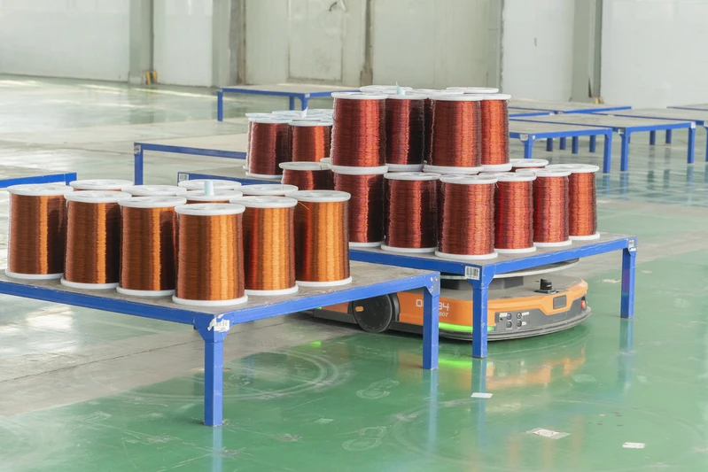
Conductor Materials and Resistivity
Copper Conductors
Copper conductors are the preferred material in the AWG system due to their high electrical conductivity, excellent mechanical strength, good solderability, and corrosion resistance. Major copper alloys include:
- C11000 ETP (Electrolytic Tough Pitch): Conductivity ≥100% IACS, oxygen content 0.02–0.04%, compliant with ASTM B49; commonly used in power cables, busbars, and magnet wire;
- C10100 OFHC (Oxygen-Free High Conductivity): Conductivity ≥101% IACS, oxygen content ≤0.0005%, compliant with ASTM B170; commonly used in vacuum electronic devices, high-frequency coaxial cables, and precision instruments;
- C10200 OF (Oxygen-Free): Conductivity ≥100% IACS, oxygen content ≤0.001%, compliant with ASTM B152;
- C12200 DHP (Phosphorus-Deoxidized): Conductivity ≥85% IACS, compliant with ASTM B152; commonly used in refrigeration tubing, automotive brake lines, and roofing sheets;
- C12000 DLP (Low-Phosphorus): Conductivity ≥90% IACS;
- C18150 / C18200 / C18400 / C18500 CuCrZr (Copper-Chromium-Zirconium): Conductivity ≥80% IACS, high-temperature softening resistance up to 500°C; used in resistance welding electrodes, sliding contacts, and IGBT heat sink substrates.
The resistivity of copper at 20°C is ρ = 1.724×10⁻⁸ Ω·m, with a temperature coefficient of resistance α = 0.00393/°C (i.e., a 10°C temperature rise increases resistance by approximately 3.93%).
Aluminum Conductors
Aluminum conductors are increasingly applied in large-power cables, transformer windings, busbars, and lightning protection systems for wind turbine blades. Major aluminum alloys include:
- 1350-O (Pure Aluminum, Annealed): Conductivity ≥61% IACS, compliant with ASTM B230/B233/B236; commonly used in power transformer windings and busbars;
- 1370: Conductivity ≥62.5% IACS; a higher-purity variant;
- 1060-O: 99.6% pure aluminum, compliant with ASTM B233;
- 1100: 99.0% pure aluminum, conductivity ≥59% IACS;
- 3003: Al-Mn alloy, conductivity ≈50% IACS;
- 5005: Al-Mg alloy, conductivity ≈53% IACS;
- 6061 / 6063: Al-Mg-Si alloys, conductivity ≈43% IACS, with high mechanical strength;
- 6201-T81: Al-Mg-Si-Fe alloy, conductivity ≥52.5% IACS; used in ACSR (Aluminum Conductor Steel Reinforced) cables.
The resistivity of aluminum at 20°C is ρ = 2.654×10⁻⁸ Ω·m, with a temperature coefficient of resistance α = 0.00403/°C. To achieve equivalent resistance, the cross-sectional area of aluminum conductors must be approximately 1.5–2 times that of copper, hence aluminum wires are commonly specified in larger mm² sizes (e.g., 50 mm² / 95 mm² / 240 mm²).
Composite Conductors
- CCA (Copper-Clad Aluminum): Copper layer volume ratio 10–15%, IACS 64–70%, compliant with ASTM B566/B576; used in RFID coaxial cables and polyethylene composite cables;
- CCS (Copper-Clad Steel): Copper layer volume ratio 21–40%, IACS 21–40%, compliant with ASTM B227/B452/B910; used in grounding conductors, railway signaling cables, and high-strength applications;
- Tinned Copper: Tin coating thickness 1–3 μm; improves oxidation resistance and solderability; compliant with ASTM B33;
- Nickel-Plated Copper: Nickel coating enhances high-temperature resistance (up to 250°C) and corrosion resistance (to acids and alkalis); compliant with ASTM B355;
- Silver-Plated Copper: Silver coating improves conductivity—especially at high frequencies—and oxidation resistance; compliant with ASTM B298;
- Copper-Plated Copper Alloys: Used in nuclear power plant cables and military-grade applications.
Conductor Types and Geometric Structures
Solid Round
Diameter range: 0.5–13 mm. Advantages: compact structure, low resistance, no skin effect losses, high mechanical strength. Disadvantages: rigidity, large bending radius, susceptibility to fatigue fracture under vibration. Typical applications: transformer windings, enameled wire busbars, distribution cabinet jumpers, main circuits in control cabinets.
Stranded
Composed of multiple small-diameter individual wires twisted together; classified into three types: concentric lay, bunch lay, and rope lay. Concentric lay is further subdivided into Class B (circular concentric stranding), Class M (metric concentric stranding), and Class S (sector-shaped conductors). Advantages: excellent flexibility, ease of bending and installation, vibration resistance. Disadvantages: slightly higher resistance than solid round conductors; skin effect must be considered. Standards: ASTM B172, B173, B174, B286, B470, B496, B784, B787, B801, B836, B837, B869, B901.
Litz Wire
Constructed by twisting multiple individually insulated fine wires (typically 36–44 AWG) in a specific braiding pattern, specifically designed to minimize skin effect and proximity effect losses at high frequencies (10 kHz–1 MHz). Litz wire structural classifications: Type 1 (single-layer insulation, single-layer stranding), Type 2 (single-layer insulation, multi-layer stranding), Type 3 (multi-layer insulation, multi-layer stranding), Type 4 (high-strength single-strand with outer insulation), Type 5 (multi-core Litz wire with overall insulation sheath). Typical applications: wireless charging, high-frequency transformers, induction heating systems, inductors, magnetic components, MRI gradient coils, planar transformers. Standards: ASTM B738, NEMA VS 1.
Compressed Round
Circular stranded conductors compressed or rolled into an elliptical or sector-shaped cross-section, maintaining identical cross-sectional area but reducing perimeter by approximately 8%–12%, thereby decreasing overall cable diameter and improving space utilization. Typical applications: sector-shaped conductors in large-power cables, automotive wiring harnesses.
Sector-shaped
Circular conductors compressed into a 120° sector shape, used in three-phase, four-wire multicore cables to reduce overall cable fill area. This geometry is recognized by both the NEC and IEC 60092 (Marine Electrical Installations).
Hollow / Tube
Circular hollow copper or aluminum tubes (wall thickness: 1–3 mm), employed in high-current busbar applications requiring active cooling, such as graphite electrode busbars in aluminum electrolysis plants and short-circuit networks for electric arc furnaces; also used in liquid-metal-cooled cables, e.g., coolant piping in nuclear reactors; and as the center conductor in coaxial cables for RF/microwave transmission.
Temperature Rise Correction and Resistance Variation
Resistance–Temperature Formula
Copper α = 0.00393/°C; aluminum α = 0.00403/°C. That is:
| Temperature (°C) | Copper Resistance Multiplier (Relative to 20°C) | Aluminum Resistance Multiplier (Relative to 20°C) |
|---|---|---|
| 20 | 1.000 | 1.000 |
| 60 | 1.157 | 1.162 |
| 90 | 1.275 | 1.283 |
| 120 | 1.394 | 1.404 |
| 155 | 1.530 | 1.545 |
| 180 | 1.629 | 1.646 |
| 200 | 1.708 | 1.728 |
| 220 | 1.786 | 1.808 |
| 250 | 1.904 | 1.931 |
Skin Effect
At high frequencies, alternating current tends to flow near the surface of a conductor, resulting in a reduction of effective cross-sectional area, and thus AC resistance (R_AC) exceeds DC resistance (R_DC). The skin depth formula is:
δ = √(ρ / (π × f × μ))
where ρ = resistivity, f = frequency, and μ = magnetic permeability (for copper and aluminum, μ ≈ μ₀ = 4π × 10⁻⁷ H/m). At 50 Hz, the skin depth for copper is approximately 9.3 mm; hence, the skin effect is negligible at power frequencies (50/60 Hz). However, it decreases to 0.65 mm at 10 kHz, 0.21 mm at 100 kHz, and 0.066 mm at 1 MHz—Litz wire is specifically engineered to mitigate this phenomenon.
Current-Carrying Capacity and Voltage Drop
Current-Carrying Capacity (NEC Table 310.16)
The National Electrical Code (NEC) 2023 Edition, Table 310.16, specifies the current-carrying capacity of THHN/THWN-2 90°C insulated copper and aluminum conductors, installed in a single conduit with three current-carrying conductors, at an ambient temperature of 30°C. Quick-reference values for common sizes are as follows:
| AWG | Copper @ 60°C (A) | Copper @ 75°C (A) | Copper @ 90°C (A) | Aluminum @ 60°C (A) | Aluminum @ 75°C (A) | Aluminum @ 90°C (A) |
|---|---|---|---|---|---|---|
| 14 | 15 | 20 | 25 | — | — | — |
| 12 | 20 | 25 | 30 | 15 | 20 | 25 |
| 10 | 30 | 35 | 40 | 25 | 30 | 35 |
| 8 | 40 | 50 | 55 | 30 | 40 | 45 |
| 6 | 55 | 65 | 75 | 40 | 50 | 60 |
| 4 | 70 | 85 | 95 | 55 | 65 | 75 |
| 2 | 95 | 115 | 130 | 75 | 90 | 100 |
| 1 | 110 | 130 | 150 | 85 | 100 | 115 |
| 1/0 | 125 | 150 | 170 | 100 | 120 | 135 |
| 2/0 | 145 | 175 | 195 | 115 | 135 | 150 |
| 3/0 | 165 | 200 | 225 | 130 | 155 | 175 |
| 4/0 | 195 | 230 | 260 | 150 | 180 | 205 |
| 250 kcmil | 215 | 255 | 290 | 170 | 205 | 230 |
| 350 kcmil | 260 | 310 | 350 | 210 | 250 | 280 |
| 500 kcmil | 320 | 380 | 430 | 260 | 310 | 350 |
Correction factors are provided in NEC Annex B and IEC 60364-5-52, Tables B.52.x. At an ambient temperature of 40°C, the correction factor is 0.88; for every 5°C rise above 30°C, the factor decreases by approximately 0.9; for six conductors in a single conduit, multiply by an additional factor of 0.8; for direct burial in soil at temperatures of 20°C, 25°C, and 30°C, the respective correction factors are 0.95, 0.90, and 0.85.
Current-Carrying Capacity per IEC 60364-5-52
IEC 60364-5-52 provides current-carrying capacity data for various installation methods: Method A1 (insulated conductors in conduit), A2 (multicore cables in conduit), B1 (insulated conductors surface-mounted on walls), B2 (multicore cables surface-mounted on walls), C (cables laid directly on cable trays), and E (free air). The reference conductor maximum operating temperature is 70°C for PVC insulation or 90°C for XLPE/EPR insulation.
GB 50054 Low-Voltage Power Distribution Design Code
China’s GB 50054-2011 standard specifies current-carrying capacities for PVC-insulated copper and aluminum conductors, including BV and BVR single-core wires installed in PVC conduits. Its methodology is analogous to that of IEC 60364-5-52, but cross-sectional areas are expressed in mm².
Voltage Drop Calculation
The NEC recommends that voltage drop in main feeders be limited to ≤3%, branch circuits to ≤5%, and total system voltage drop to ≤5%:
$$ \Delta V = 2 \times I \times R \times L \times \cos(\theta) $$
where $I$ = load current (A), $R$ = conductor resistance per unit length (Ω/km), $L$ = one-way circuit length (km), and $\cos(\theta)$ = power factor.
Example: For a 100 m (0.1 km) length of 12 AWG copper wire ($R = 5.211\ \Omega/\text{km}$), supplying a single-phase 20 A load at a power factor of 0.85, the voltage drop is calculated as:
$ \Delta V = 2 \times 20 \times 5.211 \times 0.1 \times 0.85 = 17.7\ \text{V} $ at 120 V, i.e., 14.8% — significantly exceeding the NEC recommendation. Therefore, upgrading to 10 AWG or a larger conductor size is required.
Engineering Application Scenarios
Power Transformers and Distribution Transformers
On the high-voltage side of distribution transformers, conductors commonly range from 14 AWG to 8 AWG; on the low-voltage side, conductors range from 4 AWG to 1000 kcmil. Winding temperature classes B/F/H/N (per IEC 60085) correspond to insulation materials that determine continuous operating temperatures of 130/155/180/200°C, respectively. Selection among glass-fiber-covered wire, enameled wire, and paper-covered wire depends on voltage rating and insulation requirements (see dedicated article on glass-fiber-covered wire series).
HVAC and Refrigeration Compressors
Enameled round copper wire is widely used in HVAC compressor motors, cross-flow fans, axial-flow fans, fan coil units, and condenser/evaporator fans (see dedicated article on copper foil for air-conditioning motors). Typical specifications include enameled round copper wire with diameters of 0.5–2.0 mm, stranded signal wires of 24–30 AWG, and power cables of 12–8 AWG.
Control Cabinets and PLCs
PLC input/output signals commonly employ 24 AWG twisted-pair shielded cable (e.g., Belden 9841, Alpha 2466C); analog signals commonly use 22 AWG twisted-pair shielded cable; digital signals commonly use 20–18 AWG multi-core control cable; main power circuits commonly use 14–8 AWG conductors. Low-voltage control wiring universally adopts AWG as the standard unit.
Communication and Network Cables
- Cat 5e / Cat 6 / Cat 6A: solid round copper conductors of 24 AWG;
- Cat 7 / Cat 7A: solid round copper conductors of 23 AWG;
- Cat 8: solid round copper conductors of 22–24 AWG;
- Coaxial cables: RG-6 center conductor is 18 AWG copper-clad steel; RG-11 is 14 AWG; RG-59 is 20 AWG;
- Optical fiber composite cables (OPGW / OPPC): optical fibers + aluminum-clad steel / aluminum alloy + mechanical strength expressed as AWG-equivalent cross-sectional area.
Automotive Wiring Harnesses
Low-voltage automotive wiring harnesses (< 60 V DC) extensively utilize stranded copper conductors ranging from 20 AWG to 12 AWG, with maximum conductor temperatures of 105°C (PVC), 125°C (XLPE), 150°C (ETFE), or 200°C (PTFE). For 12 V / 24 V / 48 V systems, typical conductor sizes are: signal wires of 20–22 AWG, control wires of 18 AWG, power supply wires of 14–10 AWG, and high-power circuits of 8–4 AWG. Applicable standards include ISO 6722, SAE J1128, SAE J1127, ISO 14572, LV 216, PSA B25 0530, and Renault 36-00-808.
Aerospace and Marine Wiring Harnesses
- Aerospace (AS22759 / AS81044 / BMS 13-48): conductors range from AWG 24 to 0000; insulation materials include PTFE, ETFE, XLPE, polyimide (Kapton), and fiberglass braid; temperature ratings span 150–260°C;
- Marine (IEC 60092-350 / 351 / 352 / 353 / 354 / 360 / 376): conductors range from 0.5–240 mm²; insulation materials include XLPE, EPR, and PVC; flame retardancy complies with IEC 60332-3-22/-24 Categories A, B, and C; low-smoke performance complies with IEC 61034; halogen-free performance complies with IEC 60754-1/-2;
- Railway transportation (TB/T 1484, EN 50343, EN 50264, EN 50382): conductors range from 0.5–300 mm²; insulation materials include silicone rubber, EPR, and polyolefins; low-smoke zero-halogen (LSZH) compliance applies; fire resistance complies with EN 45545-2 HL1/HL2/HL3.
Photovoltaic (PV) and Energy Storage Systems
- PV DC-side wiring: PV1-F single-core cables with cross-sectional areas of 1×4 mm² or 1×6 mm², featuring dual insulation and electron-beam cross-linked XLPE; rated temperature: 90°C; UV resistance per IEC 60811-501; ozone resistance per IEC 60811-403; service life: 25 years certified by TÜV 2 PfG 1169/07.2007;
- Energy storage PCS: DC bus conductors range from 50–300 mm²; internal battery interconnections range from 16–95 mm²; short-circuit I²t capability ranges from 10–50 kA·s; operating temperature range: −40°C to +90°C;
- Wind turbine converters: internal LCL filter reactors use conductors of 8–50 mm²; grounding conductors range from 25–95 mm²; vibration resistance complies with IEC 60068-2-6 and IEC 61373.
Medical Equipment and Explosion-Proof Mining Applications
- Medical equipment (IEC 60601-1): cardiac devices require exclusively 22–30 AWG double-shielded power cables, with insulation materials including PVC, PE, or TPE; leakage current must not exceed 0.1 mA under normal conditions and 0.5 mA under single-fault conditions;
- Mining applications (IECEx / ATEX / MSHA): conductors range from 16–300 mm²; insulation materials include EPR, XLPE, and polyurethane; flame retardancy complies with IEC 60332-3; shielding (electrostatic + electromagnetic) plus fire resistance comply with IEC 60331; armoring with steel wire or steel tape provides impact resistance and mechanical protection;
- Explosion-proof applications (UL Class I Div 1 / Div 2; ATEX Zone 1 / Zone 2): conductors range from 14–4 AWG; insulation comprises XLPE or EPR with flame-retardant PVC outer sheath; antistatic and spark-resistant properties are required; metal braid armor is applied.
Global Standard Framework
North American Standards
ASTM (American Society for Testing and Materials)
Bare conductors: ASTM B3 Soft Copper Wire, B8 Concentric-Lay Copper Stranded Conductors, B33 Tinned Soft Copper Wire, B49 Round Copper Rod, B172 Stranded Copper Conductors, B173 Concentric-Lay Stranded Copper Conductors, B174 Stranded Copper Conductors, B188 Solid Round Copper Wire, B189 Lead-Coated Copper Wire, B226 Concentric-Lay Copper Tape Conductors, B258 Standard Specification for Standard Nominal Diameters and Cross-Sectional Areas of AWG and kcmil Sizes of Solid Round Wires, B286 Concentric-Lay Stranded Copper Conductors, B298 Silver-Plated Copper Wire, B355 Nickel-Plated Copper Wire, B470 Copper-Clad Steel Wire, B496 Compact Stranded Copper Conductors, B566 Copper-Clad Aluminum Wire, B576 Copper-Clad Aluminum Resistance Welding Performance, B784 Litz Wire, B787 Compact Stranded Copper Conductors, B800 8000 Series Aluminum Alloy Wire, B801 Copper-Clad Steel Concentric-Lay Stranded Conductors, B836 Compact Round Stranded Copper Conductors, B837 Single-Strand Copper-Clad Aluminum Wire, B869 Compact Concentric-Lay Aluminum Stranded Conductors, B901 Spark Plug Wire.
UL (Underwriters Laboratories)
UL 44 Rubber-Insulated Wire, UL 83 Thermoplastic-Insulated Wire, UL 156 Metal-Clad Wire, UL 1581 Standard Reference for Electrical Wires and Cables, UL 1685 Vertical Tray Flame Test, UL 2556 Wire and Cable Test Methods, NEMA VS 1 Voltage Ratings.
NEMA (National Electrical Manufacturers Association)
NEMA WC 26 Concentric-Lay Stranded Copper Conductors, NEMA WC 53 Concentric-Lay Stranded Aluminum Conductors, NEMA WC 55 Compressed Concentric-Lay Aluminum Conductors, NEMA WC 57 Concentric-Lay Stranded Aluminum Conductors (Concentric), NEMA WC 70 Nonshielded Power Cables Rated 5–46 kV, NEMA WC 71 Nonshielded Power Cables Rated 0–2 kV, NEMA WC 72 Shielded Power Cables Rated 5–46 kV, NEMA WC 74 Shielded Power Cables Rated 5–69 kV.
CSA (Canadian Standards Association)
CSA C22.2 No. 38 Rubber-Insulated Wire, No. 49 Soft Copper Wire, No. 75 Thermoplastic-Insulated Wire, No. 126 Compressed Aluminum Conductors, No. 127 Coaxial Cables, No. 131 Series 7 Reinforced Wire, No. 210 Tinned Copper Conductors, No. 255 Nickel-Plated Copper Wire, No. 265 Silver-Plated Copper Wire, No. 273 Flame-Retardant Cables.
IEC International Standards
IEC 60228 Conductors of Copper and Aluminum for Electric Cables (Classes 1–6), IEC 60364-1 to -7 Electrical Installations of Low Voltage, IEC 60502-1 and -2 Power Cables with Extruded Insulation for Rated Voltages from 1 kV up to 30 kV, IEC 60840 Power Cables with Extruded Insulation for Rated Voltages from 30 kV up to 150 kV, IEC 62067 Power Cables with Extruded Insulation for Rated Voltages from 150 kV up to 500 kV, IEC 60287 Electric Cables — Calculation of the Current Rating, IEC 60344 Calculation of Conductor Resistance, IEC 60173 Methods of Measurement of Conductor Resistance, IEC 60028 International Standard of Resistivity of Copper, IEC 60092-350/351/352/353/354/360/376 Marine Cables, IEC 60189-1 to -7 Telecommunications Cables, IEC 60794 Optical Fibre Cables, IEC 61034 Measurement of Smoke Density, IEC 60754-1 and -2 Halogen-Free Test Methods, IEC 60332-3 Flame Retardancy Categories A/B/C, IEC 60331 Fire Resistance, IEC 60068-2-6 Vibration Testing, IEC 60364-5-52 Selection and Erection of Electrical Equipment — Current-Carrying Capacity of Cables.
Chinese National Standards (GB/T)
GB/T 3956 Conductors of Insulated Cables (identical to IEC 60228), GB/T 12706 Extruded Insulated Power Cables for Rated Voltages from 1 kV to 35 kV, GB/T 11017 110 kV Power Cables, GB/T 11018.1 and -2 Winding Wires, GB/T 18380 Flame Retardant Test Methods, GB/T 19666 Marking for Low-Smoke Halogen-Free Flame-Retardant Cables, GB/T 9330 Control Cables, GB/T 6991 Low-Voltage Cables, GB/T 13499 Crane Cables, GB/T 5013 Rubber-Insulated Cables, GB/T 5023 PVC-Insulated Cables, GB 50217 Design Code for Power Engineering Cable Systems, GB 50054 Design Code for Low-Voltage Electrical Installations, JB/T 8734 Control Cables.
Japanese Industrial Standards (JIS)
JIS C 3102 Round Copper Wire, JIS C 3605 Low-Voltage Cables, JIS C 3101 Copper and Copper Alloy Rods, JIS C 3001 Rubber-Insulated Cables, JIS C 3662 Current-Carrying Capacity Testing for Cables.
British Standards (BS)
BS 6360 Conductors of Copper and Aluminum for Electric Cables (Cross-Sectional Areas), BS 5467 Power Cables for Rated Voltages 5–33 kV, BS 6346 Cables Rated at 600/1000 V, BS 6724 Low-Smoke Halogen-Free Cables Rated at 600/1000 V, BS 7671 IET Wiring Regulations (17th Edition).
European CENELEC Standards
EN 60228 (identical to IEC 60228), HD 603 / HD 604 / HD 620 / HD 627 / HD 361 / HD 383 / HD 22 (identical to corresponding IEC standards).
International Certifications
- UL Listed: Wires intended for general use in electrical equipment;
- UL Recognized: Component-level certification;
- CSA cUL: Dual certification by CSA and UL;
- CCC: China Compulsory Certification;
- VDE: Certification by the Association of German Electrical Engineers;
- TÜV: Certification by the German Technical Inspection Association;
- CE: EU Declaration of Conformity;
- RoHS: Restriction of Hazardous Substances Directive (2011/65/EU);
- REACH: Registration, Evaluation, Authorisation and Restriction of Chemicals Regulation (EC No. 1907/2006);
- ELV: End-of-Life Vehicles Directive (2000/53/EC);
- WEEE: Waste Electrical and Electronic Equipment Directive (2012/19/EU).
Selection and Procurement Guide
Clarify Application Requirements
- Low-voltage power distribution (≤1000 V AC): BV/BVR/RV/RVV/RVVP/YC/YZ series; IEC 60228 Class 1/2/5;
- Power transformers (10–1100 kV): Paper-wrapped, enamel-coated, or fiberglass-covered winding wires; insulation selected per thermal class B/F/H/N (see Fiberglass-Covered Wire series articles);
- Motor windings: Enamel-coated round copper wire (see Enamel Wire / Copper Foil Motor series articles);
- Automotive low-voltage wiring harnesses: FLRY-A/FLRY-B/TWP/GPT/SXL/GXL/TXL; ISO 6722; SAE J1128/J1127;
- Aerospace: AS22759/AS81044/EN 2235/BMS 13-48; operating temperature 150–260°C; flame retardancy per FAR 25.869/EN 2244;
- Railway transportation: EN 50343/EN 50264/EN 50382/TB/T 1484; fire protection per EN 45545-2 HL1/HL2/HL3; low-smoke zero-halogen (LSZH);
- Photovoltaic (PV): TÜV 2 PfG 1169/07.2007; PV1-F/TÜV double insulation; 25-year service life;
- Energy storage: UL 1973/IEEE 1547/IEC 62619; operating temperature −40°C to +90°C; high short-circuit current withstand (I²t rating);
- Medical equipment: IEC 60601-1; low leakage current;
- Mining applications: IECEx/ATEX/MSHA certification; flame retardancy; armored construction; mechanical protection;
- Marine applications: IEC 60092-350 to -376; low-smoke performance per IEC 61034; halogen-free per IEC 60754.
Focus on Core Technical Parameters
Conductor material (copper/aluminum/copper-clad aluminum [CCA]/copper-clad steel [CCS]) and geometry (solid round/stranded/Litz/flattened/sector/hollow), including dimensional tolerances;
Insulation material (PVC/XLPE/EPR/PE/PFA/ETFE/PTFE/Kapton) and temperature rating (60°C/75°C/90°C/105°C/125°C/150°C/200°C/250°C);
Maximum conductor operating temperature (must match insulation thermal class);
Voltage rating (300 V / 600 V / 1000 V / 5 kV / 35 kV / 110 kV / 500 kV / 1100 kV);
Ampacity (per NEC Table 310.16 / IEC 60364-5-52 / GB 50054);
Voltage drop (NEC recommends ≤3% for branch circuits, ≤5% for feeders);
Flame retardancy rating (CMX/CMG/CM/CMR/CMP; CAT A/B/C; HL1/HL2/HL3);
Environmental resistance (UV/ozone/humidity/salt spray/chemicals/low temperature/vibration);
Mechanical robustness (bending radius/tensile strength/abrasion resistance/impact resistance);
Long-term aging performance (IEC 60216 / IEEE 101 Arrhenius lifetime curves; extrapolation to 20,000 h);
Chemical resistance (oils/acids/bases/alcohols/ketones/esters);
Radiation resistance (nuclear power/medical X-ray/γ-ray applications).
Considerations for Long-Term Partnership
Does the manufacturer possess over 30 years of export experience in electromagnetic wire?
Are all three management systems—ISO 9001, ISO 14001, and ISO 45001—certified (by SGS or equivalent accredited body)?
What are the minimum order quantity (MOQ), custom lead time, and batch-to-batch consistency performance?
Do critical processes—including conductor annealing, fiberglass braiding, and vacuum pressure impregnation (VPI)—have full traceability?
Does the manufacturer have proven project references in nuclear power plants, ultra-high-voltage (UHV), and high-voltage direct-current (HVDC) applications?
Common FAQs
How to Convert AWG to mm²?
AWG and mm² are not linearly related, but common approximations apply: decreasing AWG by one gauge number increases cross-sectional area by approximately one standard metric size. For example: 14 AWG ≈ 2.5 mm², 12 AWG ≈ 4 mm², 10 AWG ≈ 6 mm², 8 AWG ≈ 10 mm², 6 AWG ≈ 16 mm², 4 AWG ≈ 25 mm², 2 AWG ≈ 35 mm². For large conductors (e.g., 0000 AWG, 250 kcmil, 500 kcmil), consult official conversion tables.
How to Calculate Temperature Correction for Copper Conductor Resistance?
R(T) = R(20°C) × [1 + 0.00393 × (T − 20)], where the copper resistivity temperature coefficient α = 0.00393/°C. Thus, a 10°C temperature rise increases resistance by 3.93%; a 50°C rise increases it by ~19.65%; and a 100°C rise increases it by ~39.3%.
What Is Litz Wire, and Why Is It Required?
Litz wire consists of multiple individually insulated fine strands twisted or braided together, specifically engineered for high-frequency applications (10 kHz–1 MHz). At high frequencies, current flow is constrained within the conductor surface due to the skin effect, and further distorted by magnetic field interactions between adjacent conductors—the proximity effect—resulting in significantly increased AC resistance. Litz wire mitigates both effects by maximizing surface area and reducing individual strand diameter to ≤ skin depth. Typical applications include wireless charging, induction heating, inductors, high-frequency transformers, MRI gradient coils, and planar transformers.
How to Adjust Ampacity from NEC Table 310.16?
NEC Table 310.16 provides baseline ampacities for 90°C THHN/THWN-2 copper and aluminum conductors, at 30°C ambient temperature, with three current-carrying conductors in a raceway. Adjustment factors are as follows:
- Ambient temperature correction: 30°C → 40°C × 0.88; 30°C → 45°C × 0.82; 30°C → 50°C × 0.75; 30°C → 55°C × 0.67;
- Number-of-conductors correction: 3 conductors → 4–6 conductors × 0.80; 7–9 conductors × 0.70; 10–20 conductors × 0.50; 21–30 conductors × 0.45; 31–40 conductors × 0.40;
- Direct burial in soil temperature correction: 20°C × 1.00; 25°C × 0.96; 30°C × 0.90; 35°C × 0.85;
- Installation method correction: Free air × 1.00; cable tray/trough × 0.96; magnetic conduit direct burial × 0.90; PVC conduit direct burial × 0.80.
How Do AWG and kcmil Relate?
1 kcmil = 1 MCM = 0.5067 mm². Circular solid conductors commonly specify cross-sectional area in kcmil. Representative conversions: 14 AWG = 4.11 kcmil; 10 AWG = 10.4 kcmil; 6 AWG = 26.2 kcmil; 2 AWG = 66.4 kcmil; 0000 AWG = 211.6 kcmil ≈ 107.2 mm².
What Are the Differences Between Copper-Clad Aluminum (CCA) and Pure Copper?
Copper-clad aluminum (CCA) features a thin copper layer metallurgically bonded or electroplated onto an aluminum core. Advantages: lower cost (~50% of pure copper), lighter weight (~40% of pure copper), and improved corrosion resistance. Disadvantages: higher electrical resistance (conductivity ~64–70% IACS, i.e., ~65–70% that of pure copper), poor solderability (due to differing thermal expansion coefficients at the Cu–Al interface), and unsuitability for high-frequency current-carrying applications. Typical uses include RFID coaxial cable inner conductors, polyethylene composite cables, and certain building wires—though NEC strictly restricts CCA use in main building feeders.
What Are the Safety Standards for Aluminum Conductors in Power Engineering?
Aluminum conductors must comply with the following safety requirements:
- Contact surface treatment: Use antioxidant compound (for Cu–Al joints), tin-plated copper–aluminum transition connectors, or mechanical compression (not post-compression welding);
- Cross-sectional area scaling: Aluminum conductor cross-section must be ~1.5–2× that of copper to achieve equivalent DC resistance;
- Termination hardware: Use AL/CU-rated dual-metal lugs or terminals;
- Periodic inspection: Re-torque aluminum conductor terminations every 3–5 years (due to aluminum creep-induced contact resistance increase);
- Circuit breaker compatibility: Breaker terminals must be AL/CU rated, and breaker trip ratings must correspond to aluminum conductor ampacity;
- Prohibited applications: Not suitable for DC high-frequency service (aluminum oxide film becomes unstable at high frequency), environments subject to frequent vibration (aluminum creep), or humid/corrosive atmospheres.
How to Select Conductor Specifications for Fiberglass-Covered Wire?
Fiberglass-covered wire typically employs the following conductor materials: C11000 ETP round copper wire (ASTM B49), 1350-O round aluminum wire (ASTM B230/B233), or C10100 OFHC oxygen-free high-conductivity round copper wire (ASTM B152/B170). Conductor diameter/cross-sectional area selection depends on voltage class:
- Thermal classes B/F: 0.5–6.0 mm round wire;
- Thermal classes H/N: 0.5–4.5 mm round wire;
- Thermal classes 220/250: 0.3–3.5 mm round wire;
- Rectangular wire: thickness 1.0–8.0 mm × width 2–25 mm.
For detailed fiberglass-covered wire selection guidance, refer to the Fiberglass-Covered Wire series articles.
Summary
AWG (American Wire Gauge) is one of the four major global wire gauge systems, alongside SWG, IEC 60228, and GB/T 3956. A comprehensive understanding of AWG requires mastery of the following key points:
- Inverse numbering: Larger AWG numbers correspond to smaller conductor diameters;
- Mathematical foundation: Geometric progression defined by the formula dₙ = 0.127 × 92^((36−n)/39) mm;
- Standard equivalency: 0000 AWG ≈ 11.684 mm ≈ 107.2 mm² ≈ 211.6 kcmil ≈ 120 mm² (IEC);
- Temperature coefficient correction: α<sub>Cu</sub> = 0.00393/°C, α<sub>Al</sub> = 0.00403/°C;
- Ampacity: Based on NEC Table 310.16, IEC 60364-5-52, and GB 50054, referenced to ambient temperature of 30°C;
- Voltage drop: NEC recommends ≤3% for main feeders and ≤5% total for branch circuits;
- High-frequency behavior: Governed by skin effect and mitigated via Litz wire design;
- Application scope: Fully covers transformers, HVAC systems, control panels, telecommunications, automotive, marine, aerospace, photovoltaic & energy storage systems, medical equipment, and mining applications;
- Standards framework: ASTM B3–B901, UL 44/83/1581, NEMA WC 26–74, CSA C22.2, IEC 60228/60364/60502, GB/T 3956/12706/11017, JIS C 3102, BS 6360/5467/7671, EN 60228, RoHS/REACH/ELV/WEEE;
- Long-term reliability: Arrhenius-based thermal life extrapolation curve with 20,000 h rating.
Zhengzhou LP Industry Co., Ltd., a manufacturer with over 30 years of export experience in electromagnetic wire, supplies full-range products compliant with AWG, IEC, GB, and CSA standards—including copper, aluminum, copper-clad aluminum (CCA), and copper-clad steel (CCS) solid round, stranded, Litz, and rectangular conductors—as well as enameled wire, glass-fiber wrapped wire, paper-wrapped wire, and copper foil windings. These meet all application requirements across power transformers, HVAC motors, wind turbine converters, new-energy energy storage systems, industrial automation, rail transit, aerospace, and medical devices.
For technical specifications, customized solutions, or sample requests, please contact Zhengzhou LP Industry Co., Ltd.: email office@cnlpzz.com, WhatsApp 0086-19337889070.