


The reliability requirements for insulated conductors in power grid applications exceed those in general industrial scenarios by an order of magnitude. Voltage levels span from 10 kV distribution systems to ±1100 kV ultra-high-voltage direct current (UHVDC) transmission; operating frequencies extend from the standard power frequency of 50/60 Hz to high-frequency oscillations on the valve side of HVDC converters; and continuous operating temperatures frequently exceed 155 ℃—these extreme boundary conditions preclude the use of conventional enameled wire and ordinary paper-insulated wire. Glass-fiber-insulated wire is specifically engineered for such grid applications demanding high temperature resistance, intense electric field endurance, extended service life, and capability to withstand short-circuit mechanical and thermal stresses.
This article systematically addresses each node within the power grid—transmission, transformation, distribution, energy storage, traction, and grid interconnection—and provides a comprehensive review of the material system, insulation class, mechanical and dielectric properties, compliance standards, selection criteria, and acceptance protocols.
Fundamental Definition of Glass-Fiber-Insulated Wire
Glass-fiber-insulated wire belongs to a composite insulation system comprising fibrous reinforcement and impregnating varnish. Outside the conductor lies either a single or double layer of braided glass fiber tape—predominantly E-glass, with S-glass employed in select applications—followed by impregnation with heat-resistant insulating varnish and subsequent baking and curing. The insulation structure consists primarily of inorganic fibers supplemented by organic varnish—a configuration that enables sustained operation at temperatures far exceeding the upper thermal limits of conventional enameled wire.
Based on the number of braided layers, it is classified as single-layer glass-fiber-insulated wire or double-layer glass-fiber-insulated wire; based on conductor material, as copper-conductor or aluminum-conductor types; based on cross-sectional geometry, as round wire or flat wire; and based on thermal class, as B, F, H, N, R, or 250 classes. The NEMA MW 1000 standard explicitly defines these configurations under designations MW 41 to MW 44, MW 51 to MW 54, and MW 61 to MW 62.
Critical Requirements for Insulation in Power Grid Applications
Power grid applications impose four fundamental distinctions on insulation requirements for conductors, compared with those for conventional motors and transformers:
Long Service Life
Main power transmission and distribution equipment is typically designed for operational service lives of 30 years, 40 years, or even longer. The synergistic performance of the insulating varnish and glass fiber reinforcement must satisfy the criterion of “passing thermal aging tests conducted continuously for 30 years at the design temperature.”
High Dielectric Strength
For voltage classes of 35 kV and above, the insulation system must withstand lightning impulse (LI), switching impulse (SI), and power-frequency withstand voltage. The basic impulse level (BIL) ranges from 75 kV up to 1550 kV (e.g., for ±1100 kV converter transformers); such high-voltage applications cannot be supported without an insulation system exhibiting exceptionally high dielectric strength.
Resistance to Short-Circuit Electromagnetic Forces
During external short-circuit events, windings of large power transformers experience enormous axial and radial electromagnetic forces. The insulation layer must bond each turn of conductor into a mechanically integrated unit; therefore, the mechanical strength of the insulation system must meet stringent requirements.
Environmental Durability and Maintainability
Outdoor substations—and operating environments characterized by extreme cold, high humidity, salt fog, industrial pollution, and ultraviolet radiation—impose severe demands on the insulation layer. Only insulation systems qualified for environmental durability can ensure stable, long-term operation under these challenging conditions.
Material Systems
Conductor Materials
Copper conductors remain the mainstream choice for insulated wires in power grids. C11000 ETP (Electrolytic Tough Pitch) and C10100/C10200 OFHC (Oxygen-Free High-Conductivity) copper comply with ASTM B49, B115, B170, and B48, among other standards. Round wire diameters range from 0.5 to 6.0 mm; rectangular (flat) wire thicknesses range from 1.0 to 8.0 mm, with widths from 2 to 25 mm. Advantages of copper include high electrical conductivity (IACS ≥100%), excellent mechanical strength, and ease of welding; disadvantages include high density and elevated cost.
Aluminum conductors are increasingly employed in large power transformers and substations. Annealed electrical-grade aluminum alloys—such as 1350-O and 1060-O—comply with ASTM B230, B233, and B236, among other standards, and exhibit minimum electrical conductivity of 61% IACS. Aluminum offers advantages of low density and low cost; however, its lower conductivity necessitates larger cross-sectional areas, and stringent control of contact resistance at copper–aluminum transition joints is mandatory.
Specialized conductors—including aluminum-clad copper, stainless steel, and copper-clad steel—are deployed in specific applications, such as high-current grounding systems and auxiliary windings for superconducting magnets.
Glass Fibers
E-glass is the predominant choice for insulated wires in power grid applications. With alkali metal oxide content below 1%, E-glass delivers excellent electrical insulation performance and controllable manufacturing cost.
S-glass is employed where higher mechanical strength is required—for instance, in large-capacity transformers or nuclear power plant transformers subject to stringent seismic requirements. Tensile strength of S-glass exceeds that of E-glass by approximately 30%.
A-glass offers the lowest cost but exhibits marginally inferior electrical insulation performance; it is commonly used in non-critical applications or as an outer layer in composite structures.
Glass fiber filaments typically have diameters ranging from 5 to 9 μm. Each roving contains 100 to 400 individual filaments; these are twisted into yarns and subsequently woven into tapes or tubing of specified widths.
Impregnating Varnishes
Impregnating varnishes constitute a critical determinant of insulation class rating and long-term service life:
- Silicone resin varnish (H class, 180 ℃): The most widely adopted system for glass-filament-wrapped wires, offering balanced thermal stability and environmental resistance;
- Polyester-modified silicone resin varnish (F/H class, 155–180 ℃): Provides an optimal compromise between flexibility and thermal endurance; preferred for transformer windings;
- Polyimide varnish (C class, 220–240 ℃): Designed for extreme-temperature operating conditions;
- Epoxy-modified varnish (B/F class, 130–155 ℃): Recommended for humid environments or exposure to aggressive chemical media;
- Water-based eco-friendly varnish: Formulated with low volatile organic compound (VOC) content to comply with environmental directives including REACH, RoHS, and ELV.
Key Performance Parameters
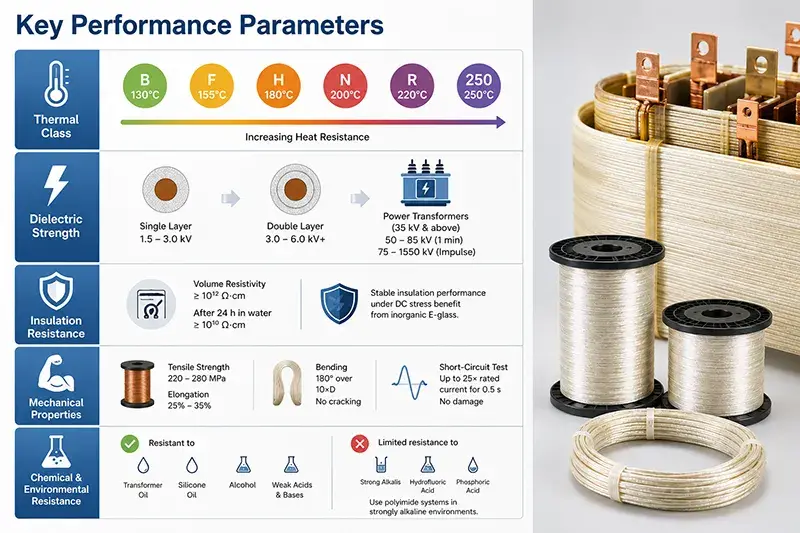
Thermal Class
In accordance with IEC 60085, IEEE C57.91, and GB/T 11021:
- Class B (130 ℃): Single-layer epoxy or polyester enamel impregnation;
- Class F (155 ℃): Polyester-modified epoxy or polyester-imide enamel impregnation—predominant for dry-type distribution transformers;
- Class H (180 ℃): Silicone resin or polyester-modified silicone resin enamel impregnation—preferred for power transformer windings and HVDC valve-side windings;
- Class N (200 ℃): Silicone rubber or modified silicone resin enamel impregnation;
- Class R (220 ℃): Polyimide enamel impregnation;
- Class 250: Polyimide-amide or specialty silicone resin enamel impregnation, enabling continuous operation at 250 ℃.
Dielectric Strength
Tested per ASTM D149, IEC 60243-1, and GB/T 1408 (using bent-rod or straight-rod specimens):
- Breakdown voltage of single-layer glass-filament-covered wire typically ranges from 1.5 to 3.0 kV;
- Breakdown voltage of double-layer glass-filament-covered wire—benefiting from staggered pinhole coverage—reaches 3.0 to 6.0 kV or higher;
- Power transformers rated at 35 kV and above generally require power-frequency withstand voltage of 50 to 85 kV (1 minute duration) and lightning impulse withstand voltage of 75 to 1550 kV (1.2/50 μs waveform)—achieved through multi-layer winding configurations and vacuum pressure impregnation (VPI) processing.
Volume Resistivity and Insulation Resistance
Per ASTM D257, IEC 60093, and GB/T 1410: Volume resistivity of glass-filament-covered wire is typically ≥10¹² Ω·cm; after immersion in water for 24 hours, it remains ≥10¹⁰ Ω·cm. For 1100 kV HVDC converter transformer windings, stability of insulation resistance is subject to more stringent requirements—prolonged application of DC voltage induces polarization effects that degrade the performance of organic insulating materials; in this context, the inherent stability of inorganic E-glass offers a distinct advantage.
Mechanical Properties
Annealed copper conductor tensile strength: 220–280 MPa; elongation after fracture: 25%–35%. Glass-filament-covered wire withstands ≥30 cycles of standardized abrasion testing (NEMA MW 1000 method); it exhibits no cracking or filament shedding during repeated 180° bending over a mandrel diameter equal to ten times the conductor diameter. During transformer short-circuit testing (IEC 60076-5), windings must endure peak currents up to 25 times rated current for 0.5 seconds without damage—the integrated structural integrity of glass-filament-covered wire combined with VPI impregnation constitutes a critical enabler of this performance.
Chemical and Environmental Resistance
Glass-filament-covered wire demonstrates excellent resistance to mineral oil, transformer oil, silicone oil, alcohol, and weak acids and bases; its ultraviolet resistance surpasses that of conventional enamel wire. Resistance to strong alkalis, hydrofluoric acid, and concentrated phosphoric acid is limited—polyimide enamel impregnation systems are recommended for strongly alkaline environments.
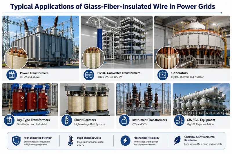
Typical Applications of Glass-Fiber-Insulated Wire in Power Grids
High-Voltage Windings of Power Transformers
High-voltage windings (cylindrical, disc-type, and interlaced configurations) of oil-immersed power transformers rated at 35 kV, 110 kV, 220 kV, and 500 kV extensively employ double-layer glass-fiber-insulated rectangular wire (copper or aluminum), combined with vacuum pressure impregnation (VPI) processing and impregnation in mineral oil or ester-based oil to establish a complete oil–paper (cellulosic) insulation system. Such windings require thermal classes F/H, single-layer dielectric strength of 3–6 kV, high electromagnetic force resistance under short-circuit conditions, and long-term thermal stability.
Ultra-High-Voltage and Extra-High-Voltage Transformers
The network-side and valve-side windings of AC transformers rated at 500 kV, 750 kV, and 1000 kV, as well as DC converter transformers rated at ±500 kV, ±800 kV, and ±1100 kV, impose the most stringent insulation requirements across the entire power grid. Windings typically adopt multi-layer insulation structures comprising glass-fiber-insulated wire, cable paper, creped paper, oil ducts, and electrostatic shields. Full type tests—including temperature-rise, impulse, short-circuit, and no-load tests—are performed prior to factory delivery. Representative projects include the Changji–Guquan ±1100 kV UHVDC transmission project, the Baihetan–Jiangsu ±800 kV project, and the Southeast Tibet–Guangdong–Hong Kong–Macao Greater Bay Area ±800 kV project.
Dry-Type and Distribution Transformers
Double-layer glass-fiber-insulated round or rectangular wire, externally coated with Class F/H impregnating varnish, is widely used in dry-type distribution transformers rated from 10 kV to 35 kV, cast resin transformers (CRT), and open ventilated dry-type (OVDT) transformers. SCB10, SCB11, SCB12, SCB13, SCB14, and SCB18 series dry-type transformers are extensively deployed in urban distribution networks, new-energy power stations, and data center power distribution systems.
GIS Busbars and Instrument Transformers
Glass-fiber-insulated wire is employed within the busbar enclosures of gas-insulated metal-enclosed switchgear (GIS), secondary windings of current and potential transformers (CT/PT), and low-voltage windings of electronic instrument transformers. Requirements include compliance with power-frequency withstand voltage tests, stable mechanical strength, and absence of partial discharge during long-term operation.
HVDC Converter Transformers, Smoothing Reactors, and Valve Tower Reactors
Valve-side windings of converter transformers—core equipment in ±800 kV and ±1100 kV converter stations—are subjected to harmonic voltages superimposed on DC, polarity-reversal voltages, and very fast transient over oltages (VFTO). The insulation structure must therefore withstand repeated polarization cycles; glass-fiber-insulated wire combined with VPI impregnation and ester-based oil impregnation represents the current mainstream solution. Similarly, the demanding mechanical stability requirements of smoothing reactors, valve tower reactors, and phase-specific (A/B/C-phase) reactors render glass-fiber-insulated wire the preferred conductor option.
Excitation Windings for Synchronous Condensers, STATCOM, SVC, and SVG
Excitation windings and filter reactor windings of large synchronous condensers (e.g., 300 Mvar, 540 Mvar), static synchronous compensators (STATCOM), static var compensators (SVC), and static var generators (SVG) demand high thermal endurance and robust short-circuit resistance—glass-fiber-insulated rectangular wire with VPI constitutes a classic solution.
Medium-Frequency Isolation Transformers in Energy Storage PCS
Medium-frequency isolation transformers in battery energy storage power conversion systems (PCS)—including those deployed in lithium iron phosphate, sodium-ion, and all-vanadium redox flow battery installations—as well as resonant inductors in bidirectional DC–DC converters and boost inductors, extensively utilize glass-fiber-insulated wire operating at frequencies of 10–100 kHz and temperature classes H/N/R. Representative projects include the Qinghai Ge’ermu Luneng Energy Storage Station, the Shandong Yishui Energy Storage Station, and the Ningxia Yanchi Energy Storage Station—each rated at the hundred-megawatt-hour scale.
LCL Filter Reactors for Grid-Connected Inverters
LCL filter reactors, boost inductors, DC-link inductors, and common-mode/differential-mode (CM/DM) reactors for photovoltaic grid-connected inverters and wind-power converters widely employ glass-fiber-insulated rectangular wire, glass-fiber-insulated round wire, and pre-impregnated DMD composite insulation. Representative projects include the Qinghai Tala Tan Photovoltaic Park, the Xinjiang Hami Wind Power Base, and the Inner Mongolia Tongliao Wind–Photovoltaic Hybrid Generation Base.
Neutral-Point Grounding Reactors and Arc-Suppression Coils
Windings of neutral-point grounding reactors, arc-suppression coils, integrated arc-suppression coil systems, and arc-suppression and grounding compensation devices—rated from 10 kV to 35 kV—utilize double-layer glass-fiber-insulated round or rectangular wire, requiring thermal class H, dielectric strength of 3–5 kV, and high resistance to short-circuit current impact.
Traction Power Supply Overhead Contact Systems
Double-layer glass-fiber-insulated rectangular wire is extensively applied in traction power supply transformers for electrified railways (27.5 kV single-phase AC), high-speed railways, and urban rail transit systems (750 V/1500 V DC), including autotransformers for AT (autotransformer) feeding systems, sectioning post transformers, and main transformers in traction substations. Applicable standards include IEC 60310, EN 45545-2 HL3 (fire protection), TB/T 3230, and GB/T 25123.
Wind and Photovoltaic Grid-Connection Step-Up Transformers
Main transformers for onshore wind farm collection and step-up substations (35 kV/66 kV), offshore wind farm high-voltage substations (220 kV/66 kV), and photovoltaic power station step-up substations (35 kV/110 kV) predominantly employ double-layer glass-fiber-insulated rectangular wire combined with VPI processing.
Emergency Diesel Generators and Containment Penetrations in Nuclear Power Plants
Stator windings of emergency diesel generators (EDG), containment electrical penetrations (CEP), reactor coolant pump motors (RCPP), and pressurizer electric heaters in nuclear power plants must comply with nuclear-grade certification standards including IEEE 323, IEEE 344, and IEEE 383. Owing to its radiation resistance (inorganic fibers are immune to radiation-induced degradation), high-temperature capability, and seismic resilience, glass-fiber-insulated wire is the preferred choice for nuclear-grade rotating machines.
Manufacturing Process
Conductor Pre-treatment
Continuous bright annealing or batch-type furnace annealing is employed to achieve the O60/O61 soft temper of the conductor; acid–alkali cleaning removes surface oxides and oil contaminants; application of coupling agents—such as silane coupling agents KH-550 and KH-560—enhances adhesion between glass fiber and copper/aluminum surfaces.
Braiding
Single-layer or double-layer braiding is performed on dedicated braiding machines. The first layer is tightly wound at a helix angle α₁, typically ranging from 30° to 60°; the second layer is superimposed in the opposite direction at a helix angle α₂, which is approximately equal in magnitude but opposite in sign to α₁—or, in some configurations, identical to α₁. Braid density is controlled by picks per inch (PPI), commonly maintained between 15 and 30 PPI. Braid pitch is determined by the ratio of spindle rotational speed to wire linear velocity.
Impregnation and Baking
Vacuum Pressure Impregnation (VPI) is the preferred process for grid-grade insulated conductors: initial vacuum evacuation removes air from interstitial voids within the fiber matrix; subsequent pressurization forces insulating varnish into the fiber substrate; finally, excess varnish is drained and the assembly is thermally cured. Atmospheric-pressure dip-and-bake (Dip & Bake) is widely adopted for high-volume production: immersion under atmospheric pressure, drip-off, and thermal curing at 150 °C to 200 °C, repeated two to four times to achieve the specified film thickness. Baking temperature is strictly governed by the chemical characteristics of the varnish base to prevent over-curing or under-curing.
Finished Product Testing
Visual and dimensional inspection—using micrometers, calipers, and optical projection instruments; dielectric testing—100% online spark test plus sampled power-frequency withstand voltage testing; mechanical testing—elongation, tensile strength, bending test, and abrasion resistance test; physicochemical testing—varnish film adhesion, solvent rub resistance, and thermal shock (175 °C × 6 h, no cracking); long-term aging evaluation—thermal class determination via IEEE 101 or IEC 60172 Arrhenius thermal life curves and 20,000-hour extrapolation methodology.
Comparison of Glass-Fiber-Enamel Wire with Other Insulation Systems
| Parameter | Enamel-Coated Wire | Paper-Insulated Wire | Glass-Fiber-Enamel Wire | Mica-Tape-Insulated Wire | Ceramic-Insulated Wire |
|---|---|---|---|---|---|
| Maximum Operating Temperature | 220 ℃ | 105 ℃ | 250 ℃ and above | 260 ℃ and above | 500 ℃ and above |
| Dielectric Strength | Low (thin-film insulation) | Medium | High (woven glass fiber + varnish impregnation) | High (multi-layer mica + resin binder) | Extremely high (inorganic ceramic) |
| Space Factor | High (compact) | Medium | Medium | Medium | Low (thick ceramic layer) |
| Short-Circuit Withstand Capability | Medium | Medium | High | High | Extremely high |
| Radiation Resistance | Poor (organic enamel degrades readily) | Medium | Excellent (inorganic fiber) | Excellent | Excellent |
| Moisture Resistance | Medium | Poor (hygroscopic) | Good (varnish seals fibers) | Medium | Good |
| Cost | Low | Medium | Relatively high | High | Extremely high |
| Typical Applications | Small motors, household appliances | Oil-immersed transformer windings | Dry-type transformers, HVDC converters, nuclear power equipment | HVDC converters, railway traction systems | Military, aerospace |
Empirical guideline: For applications requiring ≤155 ℃ operating temperature, thermal classes B/F, compact winding geometry, and high-volume production → enamel-coated wire; for oil-immersed transformer windings (compatible with mineral oil or ester-based insulating oils) → paper-insulated wire; for dry-type transformers, HVDC converters, energy storage power conversion systems (PCS), grid-connected inverters, traction power supply systems, nuclear power equipment, synchronous condenser field windings, thermal classes F/H/N/R/250, high dielectric strength requirements, and high short-circuit withstand capability → glass-fiber-enamel wire; for ultra-high-temperature environments (>260 ℃) or defense/aerospace applications → mica-tape-insulated or ceramic-insulated wire.
Standard Systems
International Standards
- IEC 60076: General specifications for power transformers;
- IEC 60146: Semiconductor converters;
- IEC 60270: Electrical measurements—Partial discharge measurements;
- IEC 60317: Specifications for enameled winding wires and glass-fibre wound wires;
- IEC 60851: Test methods for winding wires;
- IEC 60085: Electrical insulation—Thermal evaluation and classification;
- IEC 60172: Determination of temperature index of enameled winding wires and glass-fibre wound wires;
- IEEE C57.12.00, C57.12.01, C57.12.91: General requirements, testing procedures, and audible sound levels for power transformers;
- IEEE C57.91: IEEE guide for loading mineral-oil-immersed transformers;
- IEEE C57.93: IEEE guide for transformer installation and maintenance;
- IEEE 4, Std 4a: High-voltage test techniques;
- IEEE 101, IEEE 104: Methods for statistical analysis of thermal aging data and thermal evaluation of electrical insulation;
- ASTM B49, B115, B170, B48, B869: Standards for copper and aluminum conductors;
- ASTM D149, D257, D2303: Dielectric strength, volume resistivity, and tracking resistance tests for insulating materials;
- UL 1446: Systems of insulating materials;
- ICEA S-95-658 / NEMA MW 1000: General specifications for winding wires (including double-layer glass-fibre wound copper/aluminum round and rectangular wires designated MW 41 to MW 44; single-layer wires M51 to M54; and double-layer polyester-impregnated wires M61 to M62);
- IEC 60932, IEC 61378: Special standards for HVDC converter transformers;
- EN 45545-2 HL3: Highest fire protection class for railway applications.
Chinese National Standards
- GB/T 1094: Power transformers—Series;
- GB/T 6451: Technical parameters for oil-immersed power transformers;
- GB/T 25076: Toroidal transformers;
- GB/T 7672: Glass-fibre wound magnet wires (including glass-fibre wound copper/aluminum round and rectangular wires);
- GB/T 11021: Electrical insulation—Thermal evaluation and classification;
- GB/T 1408, GB/T 1410: Dielectric strength and volume resistivity;
- GB/T 4074: Test methods for winding wires;
- GB/T 1094.11, GB/T 1094.12: Dry-type power transformers;
- GB/T 25123: Traction transformers for locomotives;
- TB/T 3230, TB/T 3237: Insulation and fire protection requirements for railway transformers.
European Union / Environmental Standards
- RoHS 2.0 (2011/65/EU): Restriction of hazardous substances including lead, mercury, cadmium, hexavalent chromium, polybrominated biphenyls (PBB), and polybrominated diphenyl ethers (PBDE);
- REACH (EC No. 1907/2006): Registration, Evaluation, Authorisation and Restriction of Chemicals;
- ELV (2000/53/EC): End-of-Life Vehicles Directive;
- WEEE (2012/19/EU): Waste Electrical and Electronic Equipment Directive.
Selection and Procurement Recommendations
Clarify Operating Conditions
Continuous operating temperature: Class F/H/N/R?
Voltage class: 35 kV/110 kV/220 kV/500 kV/HVDC ±800 kV/±1100 kV?
Frequency: 50/60 Hz power frequency / 10–100 kHz medium frequency?
Short-circuit withstand capability: peak impulse current?
Environmental compliance: RoHS/REACH/EN 45545-2 HL3?
Application node: HVDC converter transformer / dry-type transformer / synchronous condenser excitation / energy storage PCS / grid-connected inverter / traction power supply / wind power step-up transformer / nuclear power plant?
Focus on Core Technical Parameters
Conductor material (copper/aluminum) and geometry (round/rectangular), including dimensional tolerances;
Glass fiber type (E-glass/S-glass) and weave density (picks per inch, PPI);
Impregnating varnish system (silicone resin/polyester-modified silicone resin/polyimide) and corresponding thermal class rating;
Dielectric strength (breakdown voltage), insulation resistance, thermal shock resistance;
Surface smoothness, enamel adhesion, solvent wipe resistance;
Compliance with target standards: NEMA MW 41/42/43/44, IEC 60317, IEEE C57, GB/T 7672;
Third-party certification requirements: UL, CE, CCC, SGS, REACH, RoHS.
Considerations for Long-Term Collaboration
Does the manufacturer possess over 30 years of electromagnetic wire export experience?
Are the three integrated management systems—ISO 9001, ISO 14001, and ISO 45001—fully certified (SGS-audited)?
What are the minimum order quantity (MOQ), custom lead time, and batch-to-batch consistency performance?
Does the manufacturer maintain full traceability across all critical processes—including conductor annealing, glass fiber braiding, and vacuum-pressure impregnation (VPI) varnishing?
What is the manufacturer’s project track record in nuclear power, UHV (ultra-high-voltage), and HVDC applications?
Zhengzhou LP Industry Co., Ltd. has accumulated over 30 years of experience in the manufacturing and export of glass-fiber-covered winding wires. Its facility occupies 60 mu (approximately 40,000 m²) and features fully integrated production lines covering conductor annealing, glass fiber braiding, and VPI impregnation. The company holds ISO 9001, ISO 14001, and ISO 45001 certifications (SGS-audited) and has obtained product certifications for UL, REACH, and RoHS. Products are supplied in strict accordance with NEMA MW 41/42/43/44, IEC 60317, and GB/T 7672. Available specifications include: round wire diameters from 0.5–6.0 mm; rectangular wire thicknesses from 1.0–8.0 mm × widths from 2–25 mm; conductor options: copper or aluminum; thermal classes covering B/F/H/N/R/250. Products are exported to more than 50 countries and regions, and are widely deployed in power transformers, HVDC converter transformers, dry-type transformers, energy storage PCS, grid-connected inverters, traction power supply systems, nuclear power plants, and synchronous condenser excitation systems. For technical data sheets, quotations, or samples, please contact us at any time:
- Email: <office@cnlpzz.com>
- WhatsApp: 0086-19337889070
Frequently Asked Questions
Why is glass-fiber-covered wire preferred over enameled wire for grid applications?
In grid applications, the combined requirements of temperature, voltage, and mechanical strength are exceptionally demanding. Enameled wire cannot satisfy these requirements: its maximum operating temperature (Class H, 220 °C) is insufficient to withstand the thermal rise in HVDC converter transformers; its dielectric strength—limited by the thin polymer film—is inadequate for power-frequency withstand and impulse tests in power transformers rated above 35 kV; and its mechanical strength fails to endure short-circuit testing in large power transformers. In contrast, glass-fiber-covered wire excels comprehensively in all three critical parameters: thermal endurance (up to Class 250 °C and beyond), dielectric strength (dielectric breakdown voltage ≥3–6 kV per layer), and mechanical strength (reinforced by braided glass-fiber layer plus impregnating varnish). Consequently, glass-fiber-covered wire is the preferred choice for insulated conductors in grid applications.
Why does an HVDC converter transformer require a specialized insulation system?
The valve-side windings of HVDC converter transformers are subjected to DC voltage superimposed with harmonic voltages, polarity-reversal voltages, and very fast transient overvoltages (VFTOs). Under DC stress, organic insulation materials suffer from space-charge accumulation, degradation due to polarization reversal, and drift in electrical conductivity. Inorganic glass fiber exhibits superior stability under DC electric fields compared to organic insulation materials—this fundamental advantage underpins the adoption of glass-fiber-covered wire combined with vacuum-pressure impregnation (VPI) and subsequent immersion in mineral oil or ester-based oil for HVDC converter transformer windings. IEC 61378 and IEC 60932 provide dedicated insulation requirements specifically for HVDC converter transformers.
Can glass-fiber-covered wire be used in medium-frequency isolation transformers for energy storage PCS, operating at 10–100 kHz?
Yes, it can be used—but only with specific material and process adaptations. These include selecting finer glass-fiber strands (individual filament diameter 5–7 μm), applying thinner impregnating varnish films (to minimize high-frequency eddy-current losses), and implementing stricter conductor surface treatment (to mitigate skin-effect losses). Candidate insulating resin systems include nano-modified silicone varnish or polyimide varnish. At operating frequencies of 50–100 kHz, the dissipation factor (tanδ) of glass-fiber-covered wire must be controlled below 0.005; above 100 kHz, specialty insulations such as polyetheretherketone (PEEK) or polyetherimide (PEI) must be considered.
What special requirements apply to glass-fiber-covered wire for nuclear power plant applications?
Insulated conductors for nuclear power plants must comply with nuclear-grade certification standards including IEEE 323 (Qualification of Class 1E Equipment for Nuclear Power Generating Stations), IEEE 344 (Seismic Qualification of Equipment), IEEE 383 (Standard for Type Tests of Class 1E Cables, Wires, and Connection Devices), and IEEE 572 (Standard for Nuclear Power Plant Instrumentation and Control Systems). Glass-fiber-covered wire is favored for emergency diesel generators (EDGs), containment electrical penetrations (CEPs), and reactor coolant pump motors (RCPPs) owing to its radiation resistance (inorganic fibers remain stable under cumulative radiation doses of 10⁶–10⁸ Gy), high-temperature capability (Class H/R), and seismic resilience (attributable to compact braided structure). Full-lifetime radiation aging data, Class 1E seismic qualification reports, and Loss-of-Coolant Accident (LOCA) test reports are mandatory.
Is glass-fiber-covered wire or enameled wire more suitable for synchronous condenser field windings?
Glass-fiber-covered wire is superior for synchronous condenser field windings. Such windings routinely operate at temperatures exceeding 180 °C (Class H and above) and must withstand high inrush currents and peak short-circuit currents—requirements that exceed the thermal and mechanical capabilities of conventional enameled wire. The established solution for large-capacity synchronous condensers (e.g., 300 Mvar and 540 Mvar units) comprises glass-fiber-covered rectangular copper conductors with VPI impregnation for rotor field windings, mica-tape-wrapped conductors for stator windings, and glass-fiber-covered rectangular copper conductors for rotor field windings. This configuration has been implemented across major pumped-storage hydropower stations—including Zhexe, Danjiang, Xuzhou, and Baoji.
Can glass-fiber-covered wire directly replace paper-insulated wire?
No, direct substitution is not permissible. Oil-immersed power transformers (e.g., 35 kV, 110 kV, and 220 kV units) widely employ paper-insulated conductors in conjunction with mineral oil or ester-based oil impregnation. The dielectric strength, thermal conductivity, and oil-flow electrification characteristics of oil-impregnated paper insulation have been validated over decades of operational experience; thus, paper-insulated wire remains the dominant solution for oil-immersed transformers. Glass-fiber-covered wire is primarily deployed in non-oil-immersed or high-temperature applications—including dry-type transformers, HVDC converter transformers, energy storage PCS, grid-connected inverters, traction power supply systems, synchronous condenser field windings, and nuclear power plant equipment—where it either replaces or complements paper-insulated wire.
What are the three most critical specifications when selecting glass-fiber-covered wire?
The three core specifications are: conductor material and purity, braid density (picks per inch, PPI), and impregnating varnish system coupled with curing process. Conductor material governs electrical conductivity and mechanical strength; braid density determines both dielectric strength and mechanical robustness; and the impregnating varnish system defines the thermal class rating, long-term thermal aging life, and environmental resistance. Failure of any one of these three parameters renders the entire conductor unreliable. It is recommended that procurement technical specifications explicitly define all three parameters and require suppliers to furnish factory type-test reports, batch-to-batch consistency documentation, and full-lifetime aging curves.
Why are NEMA MW 41/42/43/44 frequently cited in grid applications?
NEMA MW 1000 is among the most widely referenced international standards for winding wires. Specifically, MW 41 specifies double-layer glass-fiber-covered round copper wire; MW 42, double-layer glass-fiber-covered rectangular copper wire; MW 43, double-layer glass-fiber-covered round aluminum wire; and MW 44, double-layer glass-fiber-covered rectangular aluminum wire. These designations constitute the most commonly specified product standards for glass-fiber-covered wire procurement by manufacturers of grid transformers, energy storage PCS, and grid-connected inverters. When aligned with UL 1446 insulation system certification and IEEE C57.12.00 power transformer standards, they establish a complete, traceable compliance chain—from raw material to final equipment.
Zhengzhou LP Industry Co., Ltd.
Email: <office@cnlpzz.com>
WhatsApp: 0086-19337889070
Summary
Glass-fiber-covered magnet wire is applied across eight critical scenarios in power grid infrastructure: transmission, substation transformation, distribution, energy storage, traction, grid interconnection, synchronous condenser excitation, and nuclear power generation. Distinct from enamel-coated and paper-insulated wires, glass-fiber-covered magnet wire features a composite insulation system comprising single-layer or double-layer braided glass fiber combined with heat-resistant impregnating varnish. This architecture confers superior performance across five key technical parameters: thermal class ratings of Class F, Class H, Class N, Class R, and Class 250; dielectric strength of 3 to 6 kV per layer; short-circuit electromagnetic force resistance; environmental weathering resistance; and radiation resistance. In high-end grid applications—including HVDC systems, ultra-high-voltage (UHV) transmission, new-energy grid integration, energy storage systems, traction power supply, and nuclear power generation—glass-fiber-covered magnet wire serves as an irreplaceable foundational material. Selection and procurement require comprehensive evaluation of operating temperature, voltage level, frequency, short-circuit resistance, environmental compliance, and application-specific node requirements, aligned with international and national standard frameworks such as IEEE C57, IEC 60076, GB/T 1094, NEMA MW 1000, and UL 1446. Long-term reliability must be assessed rigorously using the Arrhenius thermal life curve.
For technical specifications, customized solutions, or sample requests, please contact Zhengzhou LP Industry Co., Ltd. at <office@cnlpzz.com> or via WhatsApp at 0086-19337889070.