


Fiberglass-covered enamelled wire for high-frequency equipment is a high-performance winding conductor specifically engineered for demanding high-frequency applications—including high-frequency transformers, PFC inductors, resonant inductors, induction heating coils, and servo motor windings. It features a three-layer composite insulation structure: an underlying enamel coating, an intermediate braided fiberglass sleeve, and an outer high-temperature impregnating varnish layer applied via thermal curing. This architecture delivers exceptional electrical insulation integrity, thermal stability, and mechanical robustness—making it indispensable for reliable long-term operation of high-frequency electromagnetic components under severe electrical loading, wide temperature cycling, and intense mechanical vibration.
“High-frequency equipment” generally refers to electrical and electronic systems operating within the frequency range of **20 kHz to 30 MHz**, encompassing critical applications such as switch-mode power supplies (SMPS), induction heating systems, welding power sources, telecom power systems, radar transmitters, servo drives, and wireless charging platforms. Compared with conventional 50 Hz / 60 Hz low-frequency equipment, high-frequency systems exhibit four defining characteristics:
- **Pronounced skin effect**: At high frequencies, current flows predominantly within a thin surface layer of the conductor, reducing effective conduction cross-section and significantly increasing AC resistance (*R*ac).
- **Strong proximity effect**: Magnetic coupling between adjacent conductors induces eddy currents, elevating winding losses and degrading efficiency.
- **Dominant switching losses**: Semiconductor switching devices operating at kHz–MHz frequencies generate substantial switching losses, imposing stringent thermal management requirements on magnetic components.
- **Heightened sensitivity to dielectric loss**: The permittivity (*ε*r) and loss tangent (tan *δ*) of insulating materials exert disproportionately large impacts on overall system efficiency at high frequencies—far exceeding their influence at low frequencies.
From an engineering perspective, high-frequency equipment imposes four critical performance requirements on winding conductors:
- **Thermal class rating**: Combined losses from skin-effect heating and core losses result in significantly higher operating temperatures than in low-frequency systems. Class H (180°C) and Class C (220°C) are the most widely adopted thermal classes for high-frequency windings.
- **Dielectric strength & low-loss insulation**: High inter-turn voltage stress in high-frequency transformers demands insulation with high dielectric strength (≥ 30 kV/mm) and ultra-low dielectric loss (tan *δ* < 0.015 @ 1 MHz).
- **Mechanical toughness**: Fiberglass-covered wire must withstand high-speed winding tension, lead forming, bending fatigue, and sustained mechanical vibration without insulation damage or fiber fraying.
- **Chemical compatibility**: The insulation system must resist degradation from impregnating varnishes, encapsulation resins, cooling fluids (e.g., dielectric oils or synthetic esters), and cleaning solvents encountered during manufacturing and service life.
This guide provides a systematic, application-oriented treatment of fiberglass-covered enamelled wire for high-frequency applications across five key dimensions: fundamental concepts, critical physical parameters, mainstream product types, representative application scenarios, selection methodology, and quality assurance protocols. It is intended as a complete engineering reference for design engineers working on high-frequency transformers, PFC and resonant inductors, servo motors, induction heating equipment, radar power supplies, and telecom power systems—as well as procurement specialists responsible for sourcing high-reliability winding conductors.
Fundamental Concepts of High-Frequency Equipment and Fiberglass-Over-Enamel Magnet Wire
Definition and Classification of High-Frequency Equipment
High-frequency equipment is categorized into five major application-based types: **1. Switch-Mode Power Supplies (SMPS)**: Operating frequency 20 kHz–500 kHz; power range 50 W–50 kW; typical topologies include PFC+LLC, Flyback, Forward, and Full-Bridge; applications encompass telecom power supplies, server PSUs, LED drivers, and on-board chargers (OBCs). **2. Induction Heating Systems**: Operating frequency 1 kHz–13.56 MHz; power range 1 kW–2000 kW; typical applications include medium-frequency hardening, high-frequency welding, and plasma melting. **3. Servo Drive Systems**: PWM carrier frequency 4 kHz–16 kHz; power range 50 W–75 kW; applications include industrial robots, CNC machine tools, and printing machinery. **4. Radar and Communication Systems**: Power supply section operates from DC to 30 MHz; RF section spans 1 GHz–100 GHz; applications include phased-array radar, active electronically scanned array (AESA) radar, and base station power amplifiers. **5. Wireless Power Transfer (WPT) Systems**: Operating frequency 100 kHz–13.56 MHz; power range 1 W–50 kW; applications include consumer electronics wireless charging and electric vehicle (EV) wireless charging.
Structure and Characteristics of Fiberglass-Over-Enamel Magnet Wire
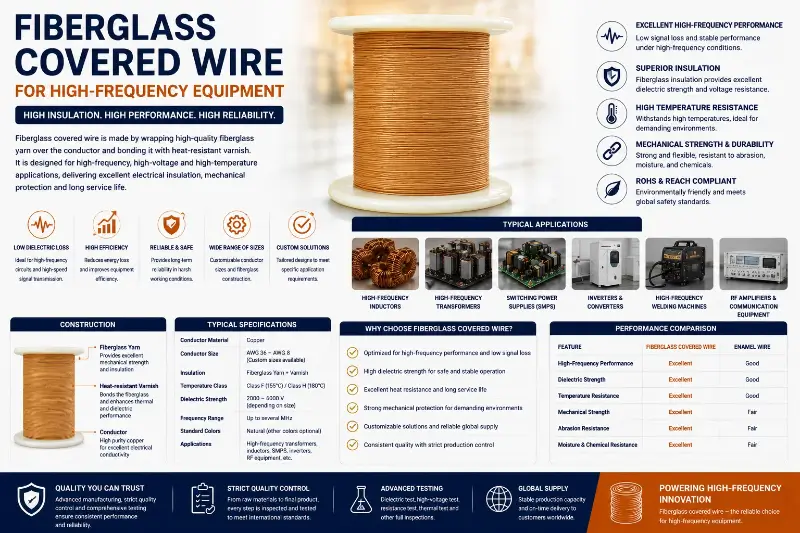
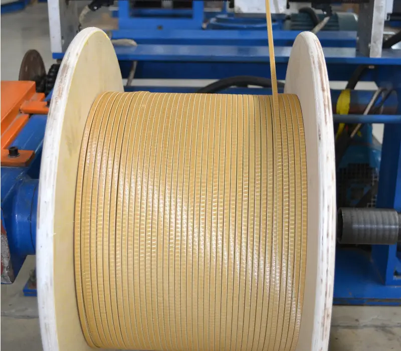
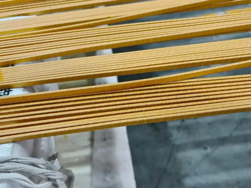
Fiberglass-covered wire (also known as glass-over-enamel wire) is a specialized winding conductor consisting of a magnet wire core overwrapped with electrical-grade continuous-filament glass yarn and subsequently impregnated with high-temperature insulating varnish. Its typical four-layer structure—ordered from innermost to outermost—is as follows: **Conductor layer**: Round copper wire (AWG 20–50), or rectangular/flat copper wire (width 2.0–25 mm, thickness 0.80–6.0 mm); material options include electrolytic tough pitch copper (C11000/C10100) or oxygen-free copper (OFC). **Enamel insulation layer**: High-temperature polymer coatings such as polyesterimide enamel wire (EIW, Class H, 180°C), polyamide-imide enamel wire (AIW, Class C, 220°C), or polyimide (PI, ≥220°C); typical thickness 30–80 μm. **Fiberglass braid layer**: Electrical-grade glass yarn (e.g., ECG 75 or ECG 150), applied in single or double layers with braid density 90%–98%. **Impregnation varnish layer**: High-performance organic silicone, polyester-modified, or epoxy resin varnish, fully penetrating the interstices of the fiberglass braid.
Key Differentiating Features vs. Conventional Enamelled Wire
Compared to standard enamelled wire, fiberglass-over-enamel wire for high-frequency applications exhibits significant differences across multiple performance dimensions: operating frequency (20 kHz–30 MHz vs. DC–1 kHz); thermal class (Class H, 180°C / Class C, 220°C vs. Class F, 155°C / Class H, 180°C); dielectric breakdown voltage (≥5 kV vs. ≥3 kV); dielectric loss (tan δ < 0.015 vs. tan δ > 0.025); mechanical robustness (high vs. medium); thermal dissipation capability (superior due to enhanced surface emissivity and structural porosity); and cost (approximately 3–8× that of conventional enamelled wire). These distinctions mandate the use of fiberglass-over-enamel wire—not standard enamelled wire—in high-frequency applications.
Key Physical Parameters of Glass-Fiber-Overcoated Magnet Wire for High-Frequency Applications
Conductor Material and High-Frequency Skin Effect Characteristics
The conductor selection for glass-fiber-overcoated magnet wire directly governs high-frequency losses and mechanical performance.
- **Round copper conductors**: Diameter range AWG 20–50 (0.80 mm–0.025 mm); commonly used gauges: AWG 20/24/26/30/34/38/42/46; conductor purity C11000 (≥99.95%) or oxygen-free C10100 (≥99.99%); applied in high-frequency transformers and resonant inductors.
- **Rectangular/flat copper conductors**: Width 2.0–25 mm, thickness 0.80–6.0 mm, width-to-thickness ratio 1.5:1 to 10:1; applied in induction heating coils and high-power high-frequency transformers.
- **Litz wire conductors**: Strand count 7–1000; individual strand diameter AWG 30–46 (0.25 mm–0.04 mm); stranding configurations include concentric or bunch stranding; applied in >1 MHz high-frequency applications and induction heating.
- **Tin-plated or silver-plated copper wires**: Used to enhance high-frequency solderability, oxidation resistance, and high-frequency conductivity (silver plating ≥105% IACS).
High-frequency skin effect is a critical constraint in conductor selection:
- Skin depth δ = 9.33 mm at 50 Hz, 0.21 mm at 100 kHz, 0.066 mm at 1 MHz, and 0.021 mm at 10 MHz.
- Engineering guideline: Conductor diameter should be < 2×δ to minimize skin-effect losses.
- Recommended Litz strand diameters:
- 100 kHz → AWG 30 (0.254 mm)
- 500 kHz → AWG 38 (0.10 mm)
- 1 MHz → AWG 42 (0.063 mm)
- 5 MHz → AWG 46 (0.04 mm)
AC-to-DC resistance ratio (Rac/Rdc):
- Round copper: 1.05–1.20 at 100 kHz; 1.50–3.00 at 1 MHz
- Litz wire: 1.02–1.05 at 100 kHz; 1.10–1.30 at 1 MHz
Glass-Fiber Braid Layer and Enamel Coating Parameters
Glass-fiber yarn specifications include:
- ECG 75 1/0 (diameter 0.075 mm, Tex 75)
- ECG 150 1/0 (diameter 0.15 mm, Tex 150)
- ECG 37 1/0 (diameter 0.037 mm, Tex 37)
Selection criteria: overall wire diameter, braid density, and mechanical strength.
- Braid coverage: 90–98% for single-layer, >99% for double-layer
- Braid angle: 45°–60° relative to wire axis
- Braid pitch: 3–15 mm
- Glass-fiber layer thickness: 0.10–0.30 mm (single-layer), 0.20–0.50 mm (double-layer); total thickness tolerance ±10%
Enamel coating thickness per IEC 60317-0-1 is classified into three grades:
- Grade 1: 30–45 μm
- Grade 2: 45–60 μm
- Grade 3: 60–80 μm
Thermal class ratings by insulation material:
- Class F (155°C): PEW (polyester enamel wire)
- Class H (180°C): EIW (polyesterimide enamel wire) — mainstream for high-frequency applications
- Class C (220°C): AIW (polyamideimide enamel wire) — premium high-frequency grade
- Class R (220°C+) or higher: PI (polyimide) — radar, aerospace, and extreme-environment applications
Impregnating Varnish and Insulation Dielectric Properties
- **Silicone varnish**: Thermal class H (180°C), dielectric strength ≥40 kV/mm, excellent flexibility; used in Class H high-frequency equipment.
- **Polyester-modified varnish**: Thermal class H (180°C), dielectric strength ≥35 kV/mm, superior adhesion; used in standard industrial high-frequency equipment.
- **Epoxy varnish**: Thermal class F (155°C), dielectric strength ≥30 kV/mm, excellent chemical resistance; used in Class F high-frequency equipment.
Dielectric properties by insulation layer configuration (tested per IEC 60851):
- Breakdown voltage:
- Single enamel layer: ≥3 kV
- Enamel + glass-fiber braid: ≥5 kV
- Double-layer glass-fiber braid: ≥7 kV
- Dielectric constant (εr) @ 1 MHz:
- Glass-fiber layer: 3.5–6.0
- Enamel layer: 2.5–4.5
- Composite insulation: 3.5–5.0
- Dissipation factor (tan δ):
- Glass-fiber layer: <0.015
- Enamel layer: <0.025
- Composite insulation: <0.015
- High-frequency optimized systems: <0.010 (preferred)
- Insulation resistance:
- Normal conditions: ≥10¹⁴ Ω·cm
- After water immersion: ≥10¹² Ω·cm
- At elevated temperature (180°C): ≥10¹⁰ Ω·cm
Mechanical Performance Requirements
- **Tensile strength**:
- Annealed round copper: 220–280 MPa
- Half-hard temper: 280–350 MPa
- Hard temper: 350–450 MPa
- Glass-fiber braid contributes 5–10% additional tensile reinforcement
- **Elongation**:
- Annealed: ≥35%
- Half-hard: ≥15%
- Hard: ≥5%
- **Abrasion resistance**:
- ASTM D3363 pencil hardness ≥4H
- Glass-fiber layer: ≥100 scratch cycles
- AIW enamel: ≥200 scratch cycles
- **Bendability**:
- Minimum bending radius: 2× wire diameter (annealed), 4× wire diameter (hard temper)
- No cracking or delamination after 90° bending
- **Vibration fatigue resistance**:
- ≥10⁸ cycles under high-frequency vibration conditions, compliant with IEC 60068 environmental testing standards
Main Product Types of Fiberglass-Over-Enamel Magnet Wire for High-Frequency Applications
Single-Layer and Double-Layer Fiberglass-Over-Enamel Wires
Single-layer fiberglass-over-enamel wire (Single Glass-Over-Enamel Wire) is the most widely used type of fiberglass-covered magnet wire in high-frequency applications. Its construction consists of conductor + enamel coating + single-layer fiberglass braid + impregnating varnish, with an overall diameter of 0.30–0.50 mm (an increase of 0.10–0.30 mm over bare wire), dielectric strength ≥ 5 kV, thermal class H (180°C) or Class C (220°C), and braid density of 90%–95%. Primary applications include standard high-frequency transformers (20 kHz–500 kHz), PFC inductors, resonant inductors, servo motor windings (Class H), and auxiliary inductors for telecom power supplies.
Double-layer fiberglass-over-enamel wire (Double Glass-Over-Enamel Wire) adds a second layer of fiberglass braid over the single-layer structure, delivering higher insulation strength. Its construction is conductor + enamel coating + fiberglass braid + fiberglass braid + impregnating varnish, with an overall diameter of 0.40–0.60 mm, dielectric strength ≥ 7 kV, thermal class H (180°C) or Class C (220°C), and braid density >99%. Key applications include high-voltage high-frequency transformers, high-Q resonant inductors, welding power supply transformers, and auxiliary inductors for radar power supplies.
Fiberglass+Enamel and Fiberglass+Mica Composite Wires
Fiberglass+enamel composite wire (equivalent to NEMA MW 50-C) features an additional layer of impregnating varnish applied over the fiberglass braid to fill interstices. Its construction is conductor + enamel coating + fiberglass braid + impregnating varnish (gap-filling), offering dielectric strength ≥ 8 kV, thermal class H (180°C), highest mechanical strength (due to cured varnish), and excellent moisture resistance. Typical applications include induction heating coils, high-frequency welding transformers, medium-frequency hardening transformers, and plasma smelting inductors.
Fiberglass+mica composite wire (Glass-Mica Covered Wire) incorporates mica tape beneath the fiberglass braid, delivering superior high-temperature performance. Its construction is conductor + mica tape + fiberglass braid + impregnating varnish, with thermal ratings of Class H (180°C), Class C (220°C), or >240°C, dielectric strength ≥ 40 kV/mm, breakdown voltage ≥ 10 kV, and cost 2–3× that of standard wires. Principal applications include high-temperature high-frequency induction heating, plasma smelting, defense-grade high-frequency equipment, and premium servo motors (Class H+).
Fiberglass+PI and Fiberglass-Covered Litz Wires
Fiberglass-over-polyimide (PI) wire (Glass-Over-PI Wire) represents a premium solution for demanding high-frequency applications. Its construction comprises conductor + PI enamel coating + fiberglass braid + impregnating varnish, with thermal class C (220°C) or C+ (240°C), low dielectric loss (tan δ < 0.008 @ 1 MHz), breakdown voltage ≥ 7 kV, and excellent radiation resistance. Key applications include radar power transformers, aerospace high-frequency equipment, defense communication power supplies, and high-end military servo drives.
Fiberglass-covered Litz wire (Glass-Over-Litz Wire) integrates multiple individually insulated strands twisted into a Litz configuration, followed by outer fiberglass braiding and varnish impregnation—making it the optimal choice for frequencies above 1 MHz. Its construction is Litz strand assembly + fiberglass braid + impregnating varnish, with individual strand diameters ranging from AWG 30 to AWG 46 (0.25 mm to 0.04 mm), strand counts from 7 to 1000, operational frequency range extending beyond 10 MHz, and Rac/Rdc ratio approaching unity at high frequencies. Primary applications include high-frequency transformers (1–10 MHz), induction heating (>100 kHz), wireless charging (100 kHz–13.56 MHz), and high-frequency resonant inductors.
Self-Bonding and Plated Fiberglass-Covered Wires
Self-bonding fiberglass-covered wire (Self-Bonding Fiberglass Covered Wire) incorporates an additional thermoplastic adhesive layer over the impregnating varnish, enabling heat-activated bonding and coil self-support. Activation temperature is 180–200°C; bond strength ≥ 10 N/cm; operating temperature rating is Class H (180°C). Typical applications include coreless high-frequency transformer windings, molded resonant inductors, end-turn shaping and reinforcement, and high-frequency inductor coil manufacturing.
Silver- or tin-plated fiberglass-covered wire (Silver/Tin-Plated Fiberglass Covered Wire) features a silver or tin plating on the conductor surface to enhance high-frequency performance and solderability. Silver plating thickness: 2–8 μm, conductivity ≥ 105% IACS; tin plating thickness: 3–10 μm, excellent solderability. Main applications include high-frequency lead-out wires, resonant inductor terminations, high-frequency transformer leads, and high-frequency PCB interconnects.
High-Frequency Transformers and Inductors: Applications
High-Frequency Transformer Construction and the Role of Fiberglass-Insulated Wire
High-frequency transformers are core magnetic components in systems such as switch-mode power supplies (SMPS), induction heating equipment, and radar power supplies—performing critical functions including voltage transformation, galvanic isolation, and power transfer. Their fundamental distinction from line-frequency (50/60 Hz) transformers lies in four key dimensions:
- **Operating frequency**: 20 kHz–1 MHz vs. 50/60 Hz;
- **Core material**: Ferrites (MnZn/NiZn) or amorphous/nanocrystalline alloys vs. silicon steel laminations;
- **Winding structure**: Multi-layer cylindrical or planar transformers vs. multi-section “pancake” windings;
- **Insulation requirements**: High-frequency dielectric performance and low dielectric loss vs. oil-impregnated paper insulation.
Fiberglass-insulated wire is widely employed across all winding sections of high-frequency transformers: primary windings (e.g., PFC output stage, resonant inductors, main transformer primary), secondary windings (rectified output, secondary filter inductors), auxiliary windings (gate-drive supplies, feedback sensing), and resonant inductors (LLC resonant tanks, series-resonant circuits).
Specification Requirements and Selection Criteria for Fiberglass-Insulated Wire in High-Frequency Transformers
High-frequency transformers impose stringent requirements on fiberglass-insulated wire across three domains:
**Electrical Requirements**:
- Operating frequency range: 20 kHz–1 MHz;
- Duty cycle: 30%–70%;
- Peak voltage: 500 V–10 kV;
- Insulation class: Reinforced insulation (basic + supplementary insulation);
- Partial discharge level: < 10 pC at 1.5 kV.
**Thermal Requirements**:
- Temperature rise: ≤ 80 K (Class H) or ≤ 100 K (Class C);
- Operating temperature range: –40°C to +180°C (Class H) or up to +220°C (Class C);
- Cooling method: Forced-air cooling (standard) or liquid cooling (high-power applications).
**Mechanical Requirements**:
- Winding tension: ≤ 30% of tensile yield strength;
- Vibration endurance: ≥ 10⁸ cycles under high-frequency vibration;
- Shock resistance: 30 g (transient mechanical shock).
Application-specific wire selection guidelines:
- **PFC inductors** (50–200 kHz, 1–10 kW): AWG 14–22, C11000 copper, EIW (polyesterimide enamel), Class H, single-layer fiberglass insulation;
- **LLC resonant inductors** (50–500 kHz, 500 W–5 kW): AWG 20–30, C11000, EIW Class H, single-layer fiberglass;
- **Flyback transformers** (20–200 kHz, 50–500 W): AWG 24–34, C11000, EIW Class H, single-layer fiberglass;
- **Telecom power transformers** (100–500 kHz, 500 W–3 kW): AWG 18–28, C11000, EIW Class H, double-layer fiberglass;
- **Radar power transformers** (50–200 kHz, 1–50 kW): AWG 16–24, C10100 (oxygen-free high-conductivity copper), polyimide (PI) insulation rated to 220°C, single-layer fiberglass;
- **Induction heating transformers** (50–400 kHz, 10–500 kW): Rectangular copper conductors, C11000, EIW Class H, single-layer fiberglass;
- **Welding power transformers** (20–100 kHz, 5–50 kW): Rectangular copper conductors, C11000, EIW Class H, double-layer fiberglass;
- **Wireless power transfer (WPT) coils** (100 kHz–13.56 MHz, 1 W–50 kW): Litz wire (AWG 30–46), C11000, UEW (urethane enamel) + fiberglass overcoat, single-layer.
Design Considerations for PFC and Resonant Inductors
**PFC (Power Factor Correction) Inductors** serve as the central energy-storage element in boost-type PFC converters. Key design parameters include:
- Inductance value: 50 μH–10 mH (scaled per power rating);
- Current ripple: 20%–40% of average current;
- Peak current: 1.2–1.5× average current;
- Core material: MnZn power ferrite;
- Air gap length: 0.5–5 mm;
- Winding configuration: Single-layer close-wound or spaced-wound cylindrical winding.
Fiberglass-insulated wire selection by power level:
- 1–3 kW: AWG 14–18, Class H, single-layer fiberglass;
- 3–10 kW: AWG 10–14, Class H, double-layer fiberglass;
- 10–30 kW: AWG 6–10, Class H, single-layer fiberglass (rectangular copper conductor).
**Resonant Inductors**, essential in LLC resonant converters and series/parallel resonant circuits, demand:
- Quality factor Q ≥ 100 (for minimal losses);
- Inductance tolerance: ±5% (critical for precise LLC resonance tuning);
- Core geometry: EE, ETD, PQ, or I-cores in ferrite;
- Winding type: Litz wire (for high-frequency operation) or solid round copper (for mid-frequency applications).
Fiberglass-insulated wire selection by operating frequency:
- 50 kHz: AWG 20–24, Class H, single-layer fiberglass;
- 100 kHz: AWG 24–28;
- 500 kHz: AWG 30–34;
- >1 MHz: Litz wire (AWG 38–42), single-layer fiberglass.
Insulation Design for High-Frequency Transformers
High-frequency transformer insulation is classified into three tiers based on safety and reliability requirements:
- **Basic Insulation**: Achieved with single-layer fiberglass-insulated wire rated ≥ 5 kV—sufficient for auxiliary supplies and signal transformers;
- **Reinforced Insulation**: Implemented using double-layer fiberglass-insulated wire rated ≥ 7 kV, or equivalent dual-barrier structures—required for telecom and medical-grade power supplies;
- **Supplementary Insulation**: Comprising fiberglass-insulated wire plus additional insulation layers (e.g., fiberglass sleeving, end insulation barriers)—used in high-voltage HF transformers to meet reinforced insulation requirements.
Minimum creepage distance requirements:
- Primary-to-secondary: ≥ 6 mm;
- Primary-to-core: ≥ 3 mm;
- Turn-to-turn: ≥ 2× nominal enamel thickness.
Induction Heating and Electromagnetic Induction Applications
Composition of Induction Heating Equipment and Requirements for Fiberglass-Insulated Wire
Induction heating is a metal heating process based on the principle of electromagnetic induction, operating across a frequency range from 1 kHz to 13.56 MHz. Classified by frequency:
- Medium-frequency (MF) induction heating (1–10 kHz) is used for melting and forging;
- High-frequency (HF) induction heating (10–100 kHz) is applied in hardening and welding;
- Ultra-high-frequency (UHF) induction heating (100 kHz–13.56 MHz) is employed for brazing and melting;
- Super-audio-frequency (SAF) induction heating (20–80 kHz) is utilized for heating small components.
An induction heating system comprises four main subsystems:
- A high-frequency power supply (including rectification, filtering, inversion, and control circuits);
- An induction coil (comprising the work coil and flux concentrators);
- A cooling system (water-cooled or oil-cooled);
- A control system (PLC, HMI, and sensors).
Requirements for fiberglass-insulated wire used in induction heating coils span three critical dimensions: **Electrical requirements**: Operating frequency 1 kHz–13.56 MHz; operating current 100–5000 A; operating voltage 200 V–10 kV; skin depth 1–0.02 mm (decreasing with increasing frequency). **Thermal requirements**: Operating temperature 180°C–300°C; water cooling (using oxygen-free copper tubing with fiberglass insulation); maximum temperature rise ≤ 100 K. **Mechanical requirements**: High vibration (high-frequency mechanical oscillation); moderate impact (e.g., forging equipment); minimum bending radius ≥ 3× conductor diameter (to accommodate coil winding).
Specifications and Design Considerations for Induction Heating Coils
Selection of coil geometry and insulation class depends on application:
- Medium-frequency hardening (1–10 kHz, 50–500 kW): rectangular copper conductor 10 × 5 mm, Class H fiberglass + mica insulation;
- High-frequency welding (100–400 kHz, 10–100 kW): rectangular copper conductor 8 × 3 mm, Class H double-layer fiberglass insulation;
- Super-audio-frequency heating (20–80 kHz, 50–200 kW): rectangular copper conductor 10 × 4 mm, Class H single-layer fiberglass insulation;
- High-frequency brazing (100 kHz–1 MHz, 1–10 kW): round copper wire AWG 14–18, Class H double-layer fiberglass insulation;
- Plasma melting (50–200 kHz, 100–2000 kW): rectangular copper conductor 15 × 6 mm, Class C fiberglass + mica insulation.
Key design considerations:
- **Conductor selection**: Rectangular copper offers large cross-sectional area, superior heat dissipation, and high mechanical strength—ideal for medium- and low-frequency applications. For high frequencies where skin effect dominates, Litz wire is recommended. Silver-plated copper is preferred where ultra-low AC resistance and enhanced high-frequency conductivity are critical.
- **Insulation design**: Single-layer fiberglass insulation ≥ 5 kV dielectric strength; double-layer fiberglass ≥ 7 kV; fiberglass + mica composite ≥ 10 kV. Vacuum-pressure impregnation (VPI) with insulating varnish fills interstices in the fiberglass layer, significantly improving overall dielectric integrity and thermal conductivity.
- **Cooling design**: Water cooling (oxygen-free copper tubing with fiberglass insulation, rated up to 250°C); air cooling (natural convection, limited to ≤ 180°C); oil cooling (mineral oil immersion, rated up to ≤ 200°C).
Electromagnetic Induction Welding Applications
Electromagnetic induction welding is widely applied in:
- Brazing (copper, iron, stainless steel);
- Soldering (electronic component assembly);
- Plastic welding (thermoplastic materials);
- Brazed joint formation (pipe fittings, cutting tools).
Frequency selection guidelines:
- 50 kHz for pipe welding;
- 100–200 kHz for tool bit brazing;
- 200–500 kHz for electronic component soldering;
- 1–13.56 MHz for precision micro-welding.
Fiberglass-insulated wire requirements for induction welding:
- Continuous operating temperature ≥ 250°C;
- Resistance to fluxes and chemical corrosion;
- Frequency range 100 kHz–13.56 MHz;
- Litz wire mandatory for applications above 1 MHz.
Servo Motors and Precision Drive Applications
Servo Drive System Architecture and Requirements for Glass-Fiber-Insulated Magnet Wire
A servo drive system comprises a servo drive, servo motor, encoder, and mechanical transmission mechanism, serving as a core component in industrial automation, robotics, and CNC machine tools. Its operational frequency spectrum includes: PWM carrier frequency of 4 kHz–16 kHz (predominant range), current-loop bandwidth of 1–4 kHz, speed-loop bandwidth of 100–500 Hz, and position-loop bandwidth of 10–100 Hz. Motor types employed include AC servo motors (PMSM—permanent magnet synchronous motors), brushless DC motors (BLDC, also PMSM), stepper motors (permanent magnet or hybrid), and linear motors (flat or tubular configurations). Glass-fiber-insulated magnet wire is applied across multiple subsystems: stator windings (main motor windings), end-turn forming (stator coil end sections), lead wires (motor leads and Hall sensor interconnects), and feedback components (encoders and resolvers).
Servo motors impose stringent requirements on glass-fiber-insulated magnet wire across three critical dimensions:
**Electrical Requirements**: PWM carrier frequency of 4–16 kHz; phase current peak values reaching 3–10× rated current; DC bus voltages of 48 V, 310 V, 560 V, or 750 V; reinforced insulation per IEC 60601-1 or equivalent standards.
**Thermal Requirements**: Operating temperature range from –40°C to +180°C (Class H); short-term peak exposure up to +200°C; cooling methods including natural convection, forced-air, or liquid cooling; maximum allowable temperature rise ≤ 120 K under Class H short-time duty.
**Mechanical Requirements**: Vibration endurance of 10⁷–10⁸ cycles; shock resistance of 30 g (transient); rotational speeds of 1000–6000 rpm (generating significant centrifugal forces); and end-turn mechanical stress due to high-tension winding processes.
Servo Motor Specification and Selection Guidelines
Selection criteria by motor type:
- **Small Servo Motors** (≤ 1 kW, 3000–6000 rpm): AWG 20–26, polyesterimide enamel wire (EIW), Class H (180°C), single-layer glass fiber insulation
- **Medium Servo Motors** (1–10 kW, 2000–4000 rpm): AWG 14–20, EIW Class H, single-layer glass fiber insulation
- **Large Servo Motors** (10–75 kW, 1500–3000 rpm): AWG 8–14, EIW Class H, double-layer glass fiber insulation
- **High-Speed Servo Motors** (5–30 kW, 6000–20,000 rpm): AWG 16–22, polyimide (PI) insulation rated ≥220°C, single-layer glass fiber
- **Robot Joint Motors** (50 W–5 kW, 3000–8000 rpm): AWG 20–26, EIW Class H, single-layer glass fiber
- **Stepper Motors** (1–1000 W, 500–3000 rpm): AWG 22–30, EIW Class H, single-layer glass fiber
- **Linear Motors** (100 W–50 kW, 5–30 m/s): rectangular copper conductors, EIW Class H, single-layer glass fiber
Stepper Motors and Robot Joint Motor Applications
**Hybrid Stepper Motors** employ Class H glass-fiber-insulated enameled wire in stator windings, widely used in 3D printing, CNC equipment, and automated systems operating at 500–3000 rpm; typical wire gauge: AWG 22–28.
**Permanent Magnet (PM) Stepper Motors**, deployed in office equipment and consumer appliances, utilize glass-fiber-insulated enameled wire in stator windings at 500–2000 rpm; typical wire gauge: AWG 24–30.
**Linear Stepper Motors** incorporate glass-fiber-insulated rectangular copper conductors in the mover windings for precision positioning and semiconductor manufacturing applications, with velocities ranging from 1–10 m/s; typical conductor size: 3 × 1.5 mm.
**Industrial Robot Joint Motors**, typically configured as PMSM or coreless (cup-type) motors, operate at power levels of 50 W–5 kW and speeds of 3000–8000 rpm. They use AWG 20–26 glass-fiber-insulated EIW (Class H), and are deployed in 6-axis articulated robots, SCARA robots, and collaborative robots (cobots).
**Collaborative Robot (Cobot) Motors**, integrating joint motor and harmonic drive units, deliver power outputs of 100 W–2 kW. They employ single-layer Class H glass-fiber-insulated magnet wire and emphasize high torque density and ultra-high efficiency (IE5).
Applications in Telecommunications Power Supplies and Radar Systems
Telecommunications Switch-Mode Power Supplies (SMPS) and Radar Power Supplies
Telecommunications switch-mode power supplies (SMPS) serve as core power equipment for communication networks, operating within a frequency range of 50–500 kHz. Glass-fiber insulated magnet wire is employed across multiple components:
- Power Factor Correction (PFC) inductors (boost-type PFC; AIW-glass fiber single-layer),
- Resonant inductors (LLC resonant topology; Class H glass-fiber single-layer),
- Main transformers (DC/DC isolation; Class H glass-fiber double-layer),
- Auxiliary transformers (gate-drive and feedback power; Class H glass-fiber single-layer),
- Output filter inductors (DC output filtering; Class H glass-fiber single-layer).
Wire gauge selection guidelines:
- For 48 V output systems: AWG 16–22, Class H glass-fiber single-layer;
- For high-density modules: AWG 22–28, Class H glass-fiber single-layer;
- For high-power modules: AWG 10–16, Class H glass-fiber double-layer.
Radar power supplies constitute critical supporting equipment for radar systems and must meet stringent requirements regarding electromagnetic compatibility (EMC), mechanical vibration, and thermal performance. Glass-fiber insulated magnet wire applications include:
- High-voltage transformers (e.g., CRT-based radar systems; AIW-glass fiber double-layer),
- Low-voltage auxiliary transformers (Class H glass-fiber single-layer),
- PFC inductors (radar-specific PFC circuits; AIW-glass fiber single-layer),
- Modulation inductors (pulse modulation; polyimide (PI) + glass-fiber insulation).
Special requirements:
- Vibration resistance per MIL-STD-810,
- Shock resistance per MIL-S-901,
- Electromagnetic compatibility per MIL-STD-461,
- Reliability with MTBF ≥ 100,000 hours.
Uninterruptible Power Supply (UPS) Systems and Wireless Charging Systems
UPS systems span power ratings from 1 kVA to 500 kVA and operate at frequencies of 20–100 kHz. Glass-fiber insulated magnet wire is used in:
- Inverter inductors (DC/AC inversion; Class H glass-fiber single-layer),
- Filter inductors (EMI filtering; Class H glass-fiber single-layer),
- Line-frequency transformers (conventional line-frequency UPS; Class H glass-fiber single-layer),
- Boost inductors (battery voltage boosting; Class H glass-fiber single-layer).
Wireless charging enables contactless energy transfer via electromagnetic induction or magnetic resonance, operating over a broad frequency range of 100 kHz–13.56 MHz. Glass-fiber insulated magnet wire applications include:
- Transmit coils (Litz wire + glass-fiber single-layer),
- Receive coils (Litz wire + glass-fiber single-layer),
- Resonant inductors (L/C resonant networks),
- Filter inductors (high-frequency rectifier filtering).
Wire gauge selection guidelines:
- Consumer electronics (5–15 W): Litz wire, AWG 38–42, glass-fiber single-layer;
- Electric vehicles (3.3–11 kW): Litz wire, AWG 30–34, glass-fiber double-layer;
- Industrial wireless charging (50 kW): Litz wire, AWG 24–28, glass-fiber double-layer.
Selection Guide and Quality Control
Selection Matrix and Frequency Matching
Selection of glass-fiber-covered magnet wire for high-frequency equipment requires comprehensive evaluation of eight key factors:
- **Operating frequency**, which determines conductor geometry (DC / 20 kHz / 1 MHz / 30 MHz);
- **Thermal class**, which dictates enamel type and impregnating resin (Class F: 155°C / Class H: 180°C / Class C: 220°C);
- **Operating voltage**, which governs number of glass-fiber layers (< 1 kV / 1–10 kV / > 10 kV);
- **Operating current**, which defines conductor cross-sectional area (< 10 A / 10–100 A / > 100 A);
- **Cooling method**, which influences insulation thickness (natural convection / forced air / liquid cooling);
- **Application**, which sets mechanical strength requirements (high-frequency transformers / inductors / induction heating / servo motors);
- **Certification requirements**, which determine qualified suppliers (UL / IEC / NEMA / MIL / industry-specific);
- **Cost budget**, which selects material grade (standard / premium / flagship).
Conductor gauge must be matched to operating frequency to minimize skin-effect losses:
- At 50 Hz (skin depth = 9.33 mm): recommend conductor diameter < 18 mm — solid round or rectangular copper;
- At 20 kHz (skin depth = 0.47 mm): recommend AWG 14–26 — solid round or rectangular copper;
- At 100 kHz (skin depth = 0.21 mm): recommend AWG 24–34 — solid round copper;
- At 500 kHz (skin depth = 0.094 mm): recommend AWG 30–40 — solid round copper or Litz wire;
- At 1 MHz (skin depth = 0.066 mm): recommend AWG 34–44 — Litz wire;
- At 5 MHz (skin depth = 0.030 mm): recommend AWG 42–46 — multi-strand Litz wire;
- At 13.56 MHz (skin depth = 0.018 mm): recommend AWG 44–46 — fine-strand Litz wire.
Thermal Class and Enamel System Matching
Enamel and glass-fiber insulation systems must be selected according to maximum operating temperature:
- ≤ 130°C: PEW (polyester enamel) + epoxy impregnating varnish + single-layer glass fiber (general industrial use);
- 130–155°C: PEW/EIW (polyesterimide enamel) + epoxy/polyester impregnating varnish + single-layer glass fiber (Class F high-frequency applications);
- 155–180°C: EIW (polyesterimide enamel) + polyester/organosilicon impregnating varnish + single-layer glass fiber (Class H high-frequency applications);
- 180–200°C: EIW/AIW (polyamideimide enamel) + polyester/organosilicon impregnating varnish + single- or double-layer glass fiber (induction heating);
- 200–220°C: AIW (polyamideimide enamel) + organosilicon/polyimide impregnating varnish + double-layer glass fiber (Class C high-frequency applications);
- 220–240°C: PI (polyimide enamel) + polyimide impregnating varnish + double-layer glass fiber (radar, aerospace).
Key Performance Indicators and Standard Systems
Key performance indicators span three critical dimensions:
**Electrical Insulation Performance**:
- Dielectric breakdown voltage ≥ 5 kV (single-layer) / ≥ 7 kV (double-layer), tested per IEC 60851;
- Dielectric constant εr = 3.5–5.0 @ 1 MHz, measured per ASTM D150;
- Dissipation factor (tan δ) < 0.015 @ 1 MHz;
- Insulation resistance ≥ 10¹⁴ Ω·cm;
- Partial discharge < 10 pC @ 1.5 kV, measured per IEC 60270.
**Mechanical Performance**:
- Tensile strength: 220–550 MPa, tested per ASTM B3;
- Elongation: ≥ 5% (hard-drawn) / ≥ 35% (annealed);
- Bend test: no cracking at 90° or 180°, per IEC 60851;
- Abrasion resistance: ≥ 100 cycles (glass-fiber layer), per ASTM D3363;
- Vibration fatigue endurance: 10⁸ cycles, per IEC 60068.
**Thermal Performance**:
- Thermal class rating (F/H/C), per IEC 60085;
- Thermal shock resistance: no cracking after 30 min at 300°C, per IEC 60851;
- Aging life: 20,000 h at rated temperature, per IEC 60172;
- Glass transition temperature (Tg): > operating temperature + 50°C, measured by DSC.
Standard systems encompass five major frameworks:
**IEC International Standards**:
- IEC 60317-31: Glass-fiber-covered round copper winding wires;
- IEC 60317-32: Glass-fiber-covered rectangular copper winding wires;
- IEC 60317-33: Glass-fiber-covered flat copper winding wires;
- IEC 60851: Test methods for enameled wires;
- IEC 60085: Electrical insulation – Thermal evaluation and classification;
- IEC 60068: Environmental testing.
**NEMA North American Standards**:
- NEMA MW 1000: General specification for magnet wire;
- NEMA MW 43-C: Glass-fiber-covered round copper wire, Thermal Class 155;
- NEMA MW 45-C: Glass-fiber-covered round copper wire, Thermal Class 180;
- NEMA MW 50-C: Polyester-glass-fiber-covered enameled wire, Class 180.
**GB/T Chinese National Standards**:
- GB/T 7672: Glass-fiber-covered round copper wire;
- GB/T 7673: Glass-fiber-covered flat copper wire;
- GB/T 6109: Series of enameled round copper wires.
**JIS Japanese Industrial Standards**:
- JIS C 3202: Series of enameled wires;
- JIS C 3216: Glass-fiber-covered enameled wires.
**UL Safety Standards**:
- UL 1446: Standard for Systems of Insulating Materials;
- UL 2353: Standard for Safety for Magnet Wire.
Supplier Evaluation and Quality Inspection
Supplier evaluation comprises eight critical dimensions:
- **Certification system**: ISO 9001 + IEC + NEMA + UL multi-system certification;
- **Industry experience**: Proven track record serving high-frequency power supply, induction heating, and servo motor manufacturers;
- **Production capability**: In-house continuous glass-fiber braiding, varnish impregnation, and controlled curing/drying;
- **Testing capability**: High-frequency dielectric testing, breakdown voltage, dissipation factor, vibration testing;
- **Quality management**: First-article inspection, in-process inspection, final inspection, and full batch traceability;
- **Technical support**: Application-specific selection assistance, high-frequency design simulation, failure root-cause analysis;
- **Sample responsiveness**: Sample lead time, customization flexibility, and collaborative engagement;
- **Delivery capability**: On-time delivery performance, production capacity, and global logistics coverage.
Critical quality inspections include:
- Dielectric breakdown voltage testing (100% sampling);
- Dissipation factor (tan δ) testing (batch sampling);
- Dimensional verification (conductor diameter, enamel thickness, glass-fiber thickness, overall diameter);
- Thermal testing (thermal shock, thermal aging, glass transition temperature);
- Mechanical testing (tensile strength, elongation, bend test, abrasion resistance);
- Chemical resistance testing (solvent resistance, oil resistance, acid/alkali resistance).
Reliability validation tests include:
- Accelerated aging: 200°C / 1000 h (to verify Class H lifetime);
- Vibration fatigue: 10⁸ cycles (simulating long-term operational stress);
- Damp heat test: 40°C / 93% RH / 1000 h (to validate performance under humid conditions);
- Thermal cycling: −40°C ↔ +180°C, 1000 cycles;
- High-frequency aging: continuous operation at rated frequency and temperature.
Summary: Engineering Selection Guide for Fiberglass-Overcoated Magnet Wire in High-Frequency Applications
Selection of fiberglass-overcoated magnet wire for high-frequency equipment is primarily governed by operating frequency and equipment type. For SMPS transformers and PFC inductors (20–500 kHz), H-class single-layer fiberglass-overcoated round magnet wire (AWG 14–30) is preferred. For LLC resonant inductors and high-frequency transformers, H-class single-layer fiberglass-overcoated Litz wire (AWG 24–38) is optimal. Induction heating coils (1 kHz–400 kHz) favor H- or C-class single-layer fiberglass-overcoated rectangular copper conductors (cross-sectional area: 10–150 mm²). Radar and aerospace power supplies require polyimide (PI)-plus-fiberglass single-layer magnet wire rated at H or C class (180–220°C). For IE4/IE5 servo motor stators, H-class single-layer fiberglass-overcoated magnet wire (AWG 14–26) is recommended. During selection, operating frequency dictates conductor geometry (round copper, rectangular copper, or Litz construction); thermal class determines enamel and impregnating varnish selection; working voltage defines the number of fiberglass layers (single or double); current rating governs conductor cross-sectional area; application environment dictates mechanical robustness requirements (tensile strength, abrasion resistance, vibration endurance); and certification requirements define acceptable supplier qualifications (NEMA MW, IEC 60317, UL 1446).
The fundamental distinction between high-frequency fiberglass-overcoated magnet wire and standard magnet wire lies in a multidimensional engineering trade-off addressing skin-effect loss, proximity-effect loss, dielectric loss, and mechanical fatigue. Standard magnet wire prioritizes cost, processability, and general-purpose compatibility; high-frequency fiberglass-overcoated wire emphasizes skin-depth matching, optimized Litz construction, tan δ minimization, vibration fatigue resistance, and compliance with UL/NEMA standards. This engineering trade-off necessitates production by specialized manufacturers certified to all three major standards: NEMA MW 1000, IEC 60317-31/32/33, and UL 1446. Key technological barriers include high-precision fiberglass braiding (≥90% coverage), uniform impregnating varnish coating (thickness tolerance ±5%), interfacial treatment between enamel and fiberglass layer (adhesion ≥10 N/cm), low-dielectric-loss enamel formulation (tan δ < 0.015), and high-frequency skin-depth simulation (using Maxwell or COMSOL). These stringent requirements explain why high-frequency fiberglass-overcoated magnet wire typically costs 3–8× more than standard magnet wire—and why PI-plus-fiberglass variants for radar/aerospace applications may reach 15–30× the cost of standard copper wire.
Core quality metrics for high-frequency fiberglass-overcoated magnet wire are dielectric loss tangent (tan δ), dielectric breakdown voltage, and skin-depth matching at operating frequency. Tan δ must be < 0.015 at 1 MHz—directly impacting system efficiency (each 0.001 reduction yields ~1–2% lower total system losses). Breakdown voltage must be ≥5 kV (single-layer) or ≥7 kV (double-layer), ensuring insulation reliability. Skin-depth matching requires individual Litz strands to have diameters ≤ 2× the calculated skin depth at operating frequency—thereby mitigating skin-effect losses. The IEC 60317-31/32/33 series provides foundational specifications for fiberglass-overcoated wires; IEC 60851 defines test methods for magnet wire; NEMA MW 1000 serves as the overarching specification for the North American market; and GB/T 7672/7673 define national standards for the Chinese market. In practical selection, five key dimensions must be jointly evaluated: operating frequency, thermal class, working voltage, application environment, and certification requirements. Suppliers holding multi-system certifications—including ISO 9001, IEC 60317, NEMA MW 1000, and UL 1446—are strongly preferred. Five critical technical evaluation criteria for assessing supplier capability are: (1) measured tan δ report (at 1 MHz), (2) measured dielectric breakdown voltage data, (3) fiberglass braid density (≥90%), (4) impregnating varnish adhesion per ASTM D3359, and (5) vibration fatigue test reports.