


Introduction
In typical applications such as electrochemical rectification, electric arc furnace (EAF) steelmaking, induction heating, energy storage power conversion systems (PCS), traction converters, marine propulsion, and grid-scale static synchronous compensators (STATCOM), the rated current on either the primary or secondary side of low-voltage, high-current transformers frequently reaches the range of 1 kA to 50 kA. When operating currents rise to several kiloamperes or even tens of kiloamperes, conventional enameled round wire, enameled rectangular wire, and copper strip windings encounter three critical engineering challenges: (i) a sharp increase in AC resistance due to skin effect and proximity effect; (ii) insufficient heat-dissipation surface area per unit current density; and (iii) localized hot-spot formation resulting from low winding space factor. Copper foil (Cu Foil) and aluminum foil (Al Foil) windings constitute a specialized winding configuration specifically developed to address these three issues—replacing multiple fine round conductors with large-area rectangular-section conductors enables uniform current distribution across the conductor width, reduces end-welding length, enhances mechanical rigidity of the winding structure, and permits implementation of interlayer main insulation using dielectric materials such as Nomex 410, Kapton, Mylar PET, DMD, and NMN between insulation layers. This paper presents a systematic review of the engineering application of Cu & Al Foil for High Current Transformer, covering material systems, key performance parameters, application families, manufacturing processes, insulation cladding methodologies, and quality inspection protocols.
Material Systems
Copper Foil Grades and Chemical Composition
The primary material for high-current transformer copper foil is C11000 electrolytic tough pitch (ETP), with a minimum copper content of 99.90% and a typical oxygen content of 0.02–0.04%. Under more demanding conditions—such as elevated-temperature operation, hydrogen-embrittlement resistance, or ultra-high conductivity requirements—C10100 oxygen-free high-conductivity copper (OFHC) or C10200 oxygen-free electronic copper (OFE) may be selected; both exhibit oxygen content below 0.001% and electrical conductivity exceeding 101% IACS. C12200 deoxidized high-phosphorus copper (DHP), containing 0.015–0.040% phosphorus, is employed where superior weldability and hydrogen-embrittlement mitigation at foil-winding weld joints are required.
Aluminum Foil Grades and Chemical Composition
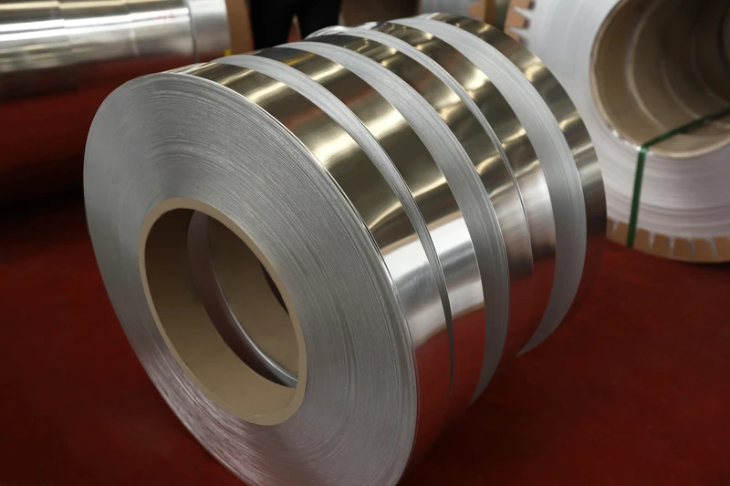
Aluminum foil used in high-current transformers commonly comprises 1-series pure aluminum grades 1050, 1060, 1070, and 1100, as well as the 3-series Al–Mn alloy 3003. The two most prevalent specifications are 1060-O (aluminum content ≥99.60%) and 3003-O (Al–Mn content 1.0–1.5%). Due to solid-solution strengthening by manganese, 3003 exhibits tensile strength approximately 30–50% higher than that of 1060, albeit at reduced electrical conductivity (~50% IACS). For applications requiring higher mechanical strength, the 5-series Al–Mg alloy 5052 (Mg content 2.2–2.8%) may be selected; however, its electrical conductivity further declines to ~35% IACS, limiting its use—on a cost–performance basis—to auxiliary structural components (e.g., foil-wound core supports) where enhanced mechanical rigidity is essential.
Physical Property Comparison
| Property | C11000 Copper Foil | 1060-O Aluminum Foil | 3003-O Aluminum Foil |
|———-|——————–|———————-|———————-|
| Density (g/cm³) | 8.94 | 2.71 | 2.73 |
| Electrical Conductivity (% IACS) | 100–101 | 61 | 50 |
| Resistivity (nΩ·m, 20°C) | 16.78 | 28.20 | 34.0 |
| Thermal Conductivity (W/m·K) | 391 | 218 | 193 |
| CTE (10⁻⁶/K, 20–100°C) | 17.0 | 23.6 | 23.2 |
| Elastic Modulus (GPa) | 110 | 69 | 70 |
| Tensile Strength, O-Tempers (MPa) | 220–280 | 70–95 | 110–130 |
| Tensile Strength, H-Tempers (MPa) | 350–400 | 110–150 | 165–210 |
| Relative Cost (per unit mass) | 1.0 (reference) | 0.30–0.35 | 0.32–0.37 |
| Relative Cost (per unit volume for equivalent conductivity) | 1.0 (reference) | 1.8–2.0 | 2.3–2.6 |
Mechanical and Formability Characteristics
Copper foil possesses an elastic modulus of 110 GPa, significantly exceeding that of aluminum foil (69 GPa); consequently, under identical thickness and width conditions, copper-wound coils withstand greater short-circuit electromagnetic forces without elastic instability. However, aluminum foil exhibits only ~30% of the density of copper, enabling substantial reduction in winding mass for large-scale transformers—offering distinct advantages in weight-sensitive applications such as traction, marine propulsion, and offshore wind power generation. Aluminum foil demonstrates superior ductility, permitting smaller minimum bend radii during deep-drawing and bending operations; yet its lower yield strength renders it more susceptible to creep relaxation under axial compressive forces applied to high-current windings.
Critical Performance
Skin Effect and Proximity Effect
Under alternating current, the current density within a conductor exhibits a non-uniform distribution, with current tending to concentrate near the conductor surface—this phenomenon is known as the skin effect. The skin depth δ is calculated as:
δ = √(2ρ / (ωμ))
where ρ denotes electrical resistivity, ω = 2πf is angular frequency, and μ is magnetic permeability. For copper foil windings operating at 50 Hz power frequency and 120°C, the skin depth is approximately 8.7 mm; at 1 kHz medium frequency, it decreases to approximately 2.0 mm; and at 10 kHz high frequency, it reduces further to only 0.65 mm. When the foil thickness is less than twice the skin depth, current distribution across the cross-section becomes approximately uniform, and the ratio of alternating-current resistance to direct-current resistance (ACR/DCR) approaches 1.0. This fundamental characteristic explains why foil windings maintain low AC losses at high frequencies relative to multi-strand round wire windings.
The proximity effect is likewise non-negligible in multi-layer foil windings. When opposing currents flow in adjacent foil layers, current is forced toward the mutually facing surfaces; when currents flow in the same direction, current is displaced toward the outer surfaces. To suppress additional losses induced by the proximity effect, interlayer main insulation structures are commonly employed—consisting of insulating films inserted between successive foil layers—thereby confining current flow within the individual conductor thickness of each layer.
Space Factor and Current Density
The space factor of foil windings is defined as the ratio of the total conductor cross-sectional area to the total winding cross-sectional area. In an ideal foil winding configuration—where the conductor consists of a continuous, rectangular-section foil—the space factor may reach 0.90–0.95, significantly exceeding that of enameled round wire windings (typically 0.45–0.55) and enameled rectangular wire windings (typically 0.65–0.75). An increased space factor implies that, for a given core window area, a larger total conductor cross-sectional area can be accommodated—thus enabling either reduced current density or a reduction in overall transformer volume.
Design current density for foil windings is typically selected within the range of 1.5–3.0 A/mm² under natural oil cooling (ONAN); under forced oil circulation (OFAF) or water cooling (OFWF), this may be elevated to 4.0–6.0 A/mm²—substantially exceeding the lower bound of the conventional enameled wire range (2.5–5.0 A/mm²).
Leakage Flux and Eddy Current Losses
Although interlayer insulation in foil windings confines eddy current losses primarily within individual layers, leakage flux still induces circulating currents in the conductors. To mitigate this, foil windings frequently incorporate flux shunt plates—or amorphous/nanocrystalline ribbons—at regular intervals (e.g., every several layers), thereby diverting leakage flux into the high-permeability core rather than into the conductors. Flux shunt plates must be fabricated from high-permeability, low-loss oriented silicon steel or amorphous thin strip, and their thickness must exceed the skin depth at the operating frequency.
Hot Spots and Temperature Distribution
Owing to their large conductor cross-sectional area and high thermal mass, foil windings exhibit slower temperature rise rates under short-time overload conditions. However, the relatively thin interlayer insulation renders them susceptible to localized hot spots if interlayer impregnation is inadequate or if the thermal conductivity of the insulation material is excessively low. Thermal conductivity values are approximately: Nomex 410 ≈ 0.10 W/m·K; DMD and NMN ≈ 0.15–0.20 W/m·K; Kapton PI film ≈ 0.12 W/m·K; and pure epoxy VPI impregnating varnish film ≈ 0.20–0.25 W/m·K. In the design of high-current transformers, hotspot temperature rise must be rigorously evaluated using the IEEE C57.91 loading guide and the IEC 60076-7 oil-immersed transformer thermal model.
Short-Circuit Strength and Mechanical Stability
The low-voltage winding of a high-current transformer experiences enormous axial and radial electromagnetic forces during external short-circuit events. Due to its rectangular cross-section and laminated construction, the foil winding possesses a substantially higher second moment of area along its width direction compared with enameled round wire windings—conferring superior resistance to radial buckling instability. However, axial short-circuit forces may induce end deformation or interlayer misalignment; therefore, epoxy end rings or fiberglass end rings are routinely installed at both ends of the foil winding to provide axial mechanical support.
Industrial Application I: Electrochemical Rectifier Transformers
Rectifier Transformers for Aluminum, Copper, and Zinc Electrolysis
Electrolytic aluminum cells operate at direct-current (DC) currents as high as 300–500 kA, with series currents ranging from 30–80 kA; the low-voltage (LV) side rated current of a single rectifier transformer typically falls within 20–60 kA. Such exceptionally high currents necessitate windings fabricated from copper or aluminum foil of large cross-sectional area. For electrolytic aluminum applications, rectifier transformers commonly employ 1060-O or 3003-O aluminum foil for LV windings, with thicknesses of 0.5–2.0 mm and widths of 200–800 mm; interlayer insulation consists of Nomex 410 or DuPont Kapton polyimide (PI) film. Key advantages include: (i) low density of aluminum foil, enabling control of overall transformer mass within transport and lifting capacity limits; (ii) continuous single-sheet foil construction, minimizing weld joints and thereby enhancing long-term operational reliability; (iii) reduced skin-effect losses in aluminum foil compared to multi-strand aluminum conductors of equivalent outer diameter under high-current conditions. In contrast, electrochemical processes such as copper, zinc, and manganese electrolysis involve comparatively lower current densities; consequently, certain manufacturers select C11000 copper foil to achieve reduced physical volume and higher power density.
Power Transformers for Electroplating, Anodizing, and Electrochemical Machining (ECM)
Power transformers supplying electroplating, electropolishing, anodizing, and electrochemical machining (ECM) typically operate at currents of 1–10 kA and voltages of 3–24 V. Historically, these transformers employed enameled rectangular wire windings; however, with increasing workpiece dimensions and stricter requirements for plating uniformity, copper foil windings have progressively replaced enameled rectangular wire. Copper foil thickness ranges from 0.3–1.0 mm, with widths of 50–300 mm; integration with epoxy resin casting or vacuum pressure impregnation (VPI) processing ensures reliable dielectric performance in humid electroplating plant environments.
Industrial Application II: Medium-Frequency Isolation Transformers for Energy Storage PCS and SST
Medium-Frequency Transformers for Power Conversion Systems (PCS)
Power Conversion Systems (PCS) employed in commercial and industrial energy storage, grid-scale energy storage, and residential energy storage require medium-frequency isolation transformers to step up low-voltage DC from batteries (48 V / 1500 V) to high-voltage DC or AC bus voltages via high-frequency isolated DC–DC converters. Typical Dual Active Bridge (DAB) converters operate at frequencies of 10–100 kHz, utilizing Medium-Frequency Transformers (MFT). At 100 kHz, the skin depth δ = √(2ρ / (ωμ)) in copper is merely 0.21 mm; therefore, conductor thickness must be constrained within the range of 0.1–0.2 mm. Copper foil windings—typically dimensioned 0.1 mm × 50 mm × 100 mm—precisely satisfy this requirement and maintain exceptionally low AC resistance under operating currents reaching several hundred amperes.
Solid-State Transformers (SST) serve as critical coupling devices between PCS and medium-voltage distribution networks. Their internal medium-frequency isolation transformers typically operate at frequencies of 1–20 kHz and exhibit per-unit power ratings spanning 100 kVA to 10 MVA. Copper foil windings for SST applications generally possess thicknesses of 0.2–0.5 mm and widths of 100–500 mm. When paired with nanocrystalline or amorphous magnetic cores, such windings enable peak efficiencies of 98.5%–99.0%.
Bidirectional EV Charging Stations and V2G Isolation Transformers
Isolation transformers deployed in bidirectional electric vehicle (EV) charging stations and Vehicle-to-Grid (V2G) applications operate at frequencies of 50–100 kHz and carry currents of 100–500 A. Within this frequency band, copper foil windings reduce losses by 30%–60% relative to enameled round-wire windings. Furthermore, their planar winding geometry facilitates enhanced core thermal management and improved control of leakage flux.
Industrial Application III: Electric Arc Furnace and Induction Heating Transformers
Electric Arc Furnace (EAF) Transformers
EAF transformers for steelmaking feature rated capacities up to 100–300 MVA, low-voltage side voltages of 100–1200 V, and currents of 20–80 kA, representing typical high-current short-circuit network loads. The low-voltage windings of EAF transformers commonly employ C11000 copper foil with thicknesses of 1.0–3.0 mm and widths of 300–1200 mm, insulated interlayer-wise with Nomex 410, Kapton PI, or glass fiber cloth. Copper foil windings offer the following advantages: (i) superior short-circuit mechanical strength; (ii) planar end surfaces facilitating reliable bolted or welded connections to water-cooled short-circuit busbars; and (iii) high space factor, enabling higher current density within constrained core window dimensions.
The operating current of EAF transformers contains substantial harmonic content (2nd, 3rd, 4th, 5th harmonics), resulting in reduced skin depth δ = √(2ρ / (ωμ)) at harmonic frequencies compared to fundamental frequency. Consequently, foil thickness is subject to stricter constraints: copper foil thickness is typically limited to ≤2.0 mm, and a magnetic flux shunt plate is inserted every 3–5 foil layers.
Induction Heating Power Supply Transformers
Induction heating power supplies operate over a frequency range of 1 kHz–500 kHz. Matching transformers interfacing induction coils and resonant capacitors must exhibit low losses under medium- to high-frequency excitation. Medium-frequency (1–10 kHz) induction heating power supplies commonly utilize copper foil windings; high-frequency (>100 kHz) systems predominantly employ hollow copper tubing or Litz wire. For medium-frequency applications, copper foil thickness is typically specified as 0.3–0.8 mm.
Vacuum Arc Remelting (VAR), Electron Beam (EB), and Medium-Frequency Furnace Transformers
Transformers for vacuum metallurgical processes—specifically those paired with vacuum arc remelting (VAR) furnaces and electron beam (EB) furnaces—typically deliver currents of 5–30 kA at voltages of 30–100 V. Copper foil windings are widely adopted in these high-end metallurgical systems owing to their low outgassing rate under vacuum conditions and robust insulation integrity.
Industrial Application IV: Traction, Marine Propulsion, and Electric Propulsion
Traction Transformers for Electric Locomotives and High-Speed Trains
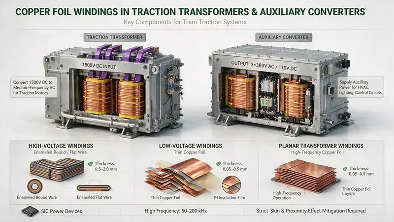
Onboard traction transformers for electric locomotives and high-speed trains operate at primary voltages of 25 kV (overhead catenary) or 1.5/3 kV DC (metro, third-rail), with the low-voltage side feeding traction converters that rectify power for traction motors. The volume and weight of onboard traction transformers are strictly constrained by vehicle clearance limits; therefore, copper foil windings are commonly employed instead of enameled round wire windings to improve space factor and reduce mass. Certain windings in CRH-series high-speed train traction transformers utilize copper foil of 0.5–1.0 mm thickness, combined with Nomex 410 insulation and silicone oil cooling.
Integrated Full Electric Propulsion (IFEP) Transformers for Marine Applications
Propulsion transformers within Integrated Full Electric Propulsion (IFEP) systems for naval vessels carry currents up to 5–15 kA at voltages of 6.6–13.8 kV. Due to stringent requirements on transformer volume, weight, vibration resistance, and shock resistance—mandated by IEEE 833 or GJB 150 series naval environmental standards—copper foil windings have become the predominant solution, owing to their high power density and mechanical stability. Conductor material is typically selected from C11000 or C10100 OFHC copper, with foil thicknesses ranging from 0.5–2.0 mm, integrated with vacuum pressure impregnation (VPI) processing and NOMEX/DMD composite insulation.
Step-Up Transformers for Wind Power and Offshore Wind Farms
Step-up transformers (inter-array transformers) deployed within offshore wind farms exhibit ratings of 5–20 MVA and voltage ratios of 66 kV/34 kV or 34 kV/10 kV. Installed either inside wind turbine towers or on offshore substation platforms, these transformers are highly sensitive to mass and volumetric constraints. Aluminum foil windings—leveraging low density and favorable machinability—are increasingly adopted in medium- and small-capacity offshore wind step-up transformers. In contrast, large-scale onshore wind farm step-up transformers continue to rely primarily on copper foil or enameled rectangular wire windings.
Manufacturing Processes
Foil Rolling and Annealing
Cu & Al foil for High Current Transformer is primarily manufactured via three process routes:
1. Rolling-Annealing (RA): Electrolytic copper rod or aluminum rod is subjected to multi-pass cold rolling to the target thickness (0.05–3.0 mm), followed by recrystallization annealing in a protective atmosphere (typical annealing temperature for copper foil: 400–550 °C; for aluminum foil: 300–380 °C). The RA process is suitable for medium-to-thick foils of thickness 0.2–3.0 mm, with maximum foil width up to 1200 mm.
2. Continuous Casting and Rolling (CCR): Molten metal is cast into slabs via a continuous caster and subsequently rolled to the target thickness using a multi-stand tandem mill. The CCR process is suited for high-volume production, yielding foils of thickness 0.5–3.0 mm and width up to 1500 mm, at lower cost than RA.
3. Conform Continuous Extrusion: Aluminum rod is directly extruded into aluminum foil using a Conform continuous extrusion machine—particularly suitable for small-batch custom production of aluminum alloy foils such as 3003-O and 6063. Conform extrusion of copper is rarely applied due to copper’s high-temperature strength and associated die wear issues.
Dedicated Foil Winding Machines
Foil windings must be fabricated on specialized foil winding machines. Core components include:
1. Foil Payoff Unit: Capable of handling foil reels weighing 50–500 kg, equipped with tension control (typical tension: 20–100 N);
2. Insulating Film Payoff Unit: Synchronously feeds insulating materials including Nomex 410, Kapton PI, Mylar PET, DMD, and NMN;
3. Winding Mandrel: Supports winding of coils with diameters ranging from 50–2000 mm;
4. Tension Rollers and Edge-Guidance System: Ensures foil remains wrinkle-free and properly aligned during winding;
5. End-Terminal Welding Station: Incorporates laser welding, electron beam (EB) welding, TIG welding, MIG welding, resistance welding, and ultrasonic welding (USW).
Precise control of winding tension is critical: excessive tension induces plastic elongation and reduces cross-sectional area; insufficient tension causes interlayer looseness and lowers space factor. Typical winding tension is set at 5%–10% of the foil’s tensile strength.
End-Terminal Welding Technologies
End-terminal leads of foil windings constitute a critical quality control point in transformer manufacturing. Common welding methods include:
1. TIG Welding (Tungsten Inert Gas): Provides stable weld quality for Cu-to-Cu connections (e.g., copper foil to copper busbar);
2. MIG Welding (Metal Inert Gas): Suitable for Al-to-Al connections (e.g., aluminum foil to aluminum busbar);
3. Laser Welding: Delivers localized high-energy heating, ideal for thin foils (<0.5 mm) and precision lead attachments;
4. Electron Beam Welding (EBW): High-energy beam welding performed under vacuum, appropriate for critical welds on oxygen-free copper (OFC) foils such as ETP, OFHC, OFE, and DHP;
5. Resistance Welding: Spot or projection welding, enabling rapid joining of thin aluminum foil to aluminum strip;
6. Ultrasonic Welding (USW): A solid-state bonding technique especially suited for Al–Cu dissimilar-metal transition joints; however, formation of intermetallic compounds (IMC) must be rigorously controlled.
Surface Treatment and Insulation Encapsulation
Insulation encapsulation of high-current transformer foil windings adopts multiple configurations:
1. Tape-Wound Insulation: Nomex 410 paper, Kapton polyimide (PI) film, Mylar PET film, DMD (polyester film + polyester nonwoven), and NMN (polyester film + aramid nonwoven);
2. Varnish-Coated Insulation: Application of polyamide-imide (PAI), polyimide (PI), or polyester-imide (PEI) varnishes onto foil surfaces, forming an insulation layer of thickness 0.02–0.10 mm;
3. Impregnation Insulation: Epoxy or polyester resin infiltrated into interlayer gaps and end regions of foil windings via Vacuum Pressure Impregnation (VPI), followed by thermal curing to form monolithic insulation;
4. Chemical Vapor Deposition (CVD) Insulation: Parylene C deposited uniformly onto foil surfaces under vacuum via CVD, yielding conformal insulation films of thickness 0.005–0.050 mm—particularly advantageous for high-frequency, high-power-density microelectronic transformers;
5. Metallic Plating: Nickel (Ni), tin (Sn), or silver (Ag) plating applied to foil surfaces to enhance solderability, oxidation resistance, and electrical conductivity.
Vacuum Pressure Impregnation (VPI) and Casting
Following foil winding completion, high-current transformers typically undergo either VPI or epoxy casting:
1. VPI Process: Pre-dried foil windings are placed in a vacuum chamber and evacuated to <100 Pa, then impregnating varnish (epoxy or polyester) is introduced and pressurized to 0.2–0.6 MPa for 2–6 hours. Final curing occurs in an oven (typically 80–150 °C × 8–24 h). VPI ensures complete penetration of varnish into interlayer voids, eliminating air pockets and partial discharge sites.
2. Epoxy Casting Process: Epoxy resin is poured into a mold enclosing the foil winding—commonly employed for dry-type transformers. Epoxy-cast transformers achieve partial discharge levels <5 pC, exhibit high dielectric strength, and are suitable for humid, dusty, or corrosive gaseous environments.
Quality Inspection and Certification
Material-Level Testing
Material-level testing for Cu & Al foil used in high current transformers includes the following items:
1. Chemical Composition: ASTM B115 for copper foil, ASTM B479 for aluminum foil, GB/T 5231 for wrought copper, and GB/T 3190 for wrought aluminum and aluminum alloys;
2. Resistivity/Conductivity: ASTM B193 for volume resistivity, ASTM B566 for aluminum wire resistivity;
3. Mechanical Properties: ASTM E8 for tensile testing, ASTM E384 for microhardness;
4. Dimensional Accuracy: ISO 4287 for surface roughness, ISO 4288 for roughness parameters;
5. Surface Quality: ASTM B576 for grain structure of lead-bonding copper foil, ASTM B577 for hydrogen embrittlement susceptibility of copper foil;
6. Thermal Conductivity: ASTM E1461 for flash method, ASTM E228 for hot-wire method;
7. Coefficient of Thermal Expansion (CTE): ASTM E228 for push-rod dilatometry.
Insulation and Dielectric Testing
Dielectric testing of interlayer and end-winding insulation for foil windings includes:
1. Dielectric Breakdown Voltage: ASTM D149, IEC 60243-1;
2. Dielectric Constant and Loss Factor: IEC 60250;
3. Volume and Surface Resistivity: IEC 60093, ASTM D257;
4. Partial Discharge (PD): IEC 60270;
5. Tracking Resistance: IEC 60112, ASTM D2303.
Transformer System-Level Testing
Foil-wound transformers shall undergo the following system-level tests prior to factory shipment:
1. Turn-to-Turn Insulation Test: Impulse voltage test per IEC 60076-1;
2. Applied Voltage Withstand Test: Power-frequency and lightning impulse withstand tests per IEC 60076-3;
3. Temperature Rise Test: Temperature rise measurement under specified load conditions per IEC 60076-2;
4. Short-Circuit Test: Verification of short-circuit withstand capability per IEC 60076-5;
5. No-Load and Load Loss Measurements: Measurement of no-load loss P₀ and load loss Pₖ per IEC 60076-1;
6. Partial Discharge Measurement: PD magnitude measurement per IEC 60270;
7. Noise Measurement: Sound pressure level measurement per IEC 60076-10;
8. Insulating Oil Testing for Oil-Immersed Transformers: Oil sampling and testing per IEC 60567 for dielectric breakdown voltage, water content, and tanδ.
Application-Specific Certification
1. Power Transformers: IEC 60076 series, IEEE C57.12.00, GB/T 1094 series;
2. Rectifier Transformers: IEEE C57.18.10, IEC 60146 series for semiconductor converters;
3. Medium-Frequency / High-Frequency Transformers: IEC 61378 for converter transformers;
4. Dry-Type Transformers: IEC 60076-11, IEEE C57.12.01;
5. Wind Power Transformers: IEC 61400-1 for wind energy systems, IEC 62271-200 for high-voltage switchgear;
6. Photovoltaic / Energy Storage Transformers: UL 1741 for photovoltaic inverters, IEEE 1547 for interconnection of distributed resources;
7. Railway Traction Transformers: EN 45545-2 HL3 for fire protection, IEC 60077 for railway locomotive transformers;
8. Marine Transformers: IEEE 833 / C57.157 for marine service transformers, ABS Rules, DNV Rules;
9. Automotive-Grade Transformers: IATF 16949, AEC-Q100, RoHS 2.0, REACH, ELV 2000/53/EC;
10. RoHS / REACH Compliance: EU RoHS 2.0 (2011/65/EU) and REACH (EC 1907/2006) restrictions on lead, cadmium, hexavalent chromium, polybrominated biphenyls (PBB), and polybrominated diphenyl ethers (PBDE).
Selection Engineering
Selection Procedure
The selection of Cu & Al foil for high current transformer shall follow the procedure below:
1. Specification of Electrical Parameters: Rated capacity, rated voltage, number of phases, frequency, winding connection group designation, impedance voltage, load loss, no-load loss, and insulation class;
2. Specification of Environmental Conditions: Altitude (affecting external insulation and temperature rise), ambient temperature (affecting rated capacity), relative humidity, pollution degree, marine/salt mist/chemical corrosion exposure;
3. Specification of Cooling Method: ONAN (oil-immersed natural cooling), ONAF (oil-immersed forced-air cooling), OFAF (forced-oil circulation with forced-air cooling), OFWF (forced-oil circulation with water cooling), AN (dry-type natural cooling), AF (dry-type forced-air cooling), AFWF (dry-type water cooling);
4. Specification of Insulation Class: Class A (105 °C), Class E (120 °C), Class B (130 °C), Class F (155 °C), Class H (180 °C), Class N (200 °C), Class R (220 °C), 250-class (250 °C);
5. Conductor Selection: Comprehensive trade-off among current density, temperature rise, weight, volume, and cost;
6. Insulation Design: Inter-layer voltage, ground voltage, impulse voltage, creepage distance;
7. Structural Design: Core configuration (core-type/shell-type), winding arrangement (coaxial/interleaved), lead-out configuration, mechanical support, short-circuit withstand capability;
8. Quality Inspection: Type tests, routine tests, special tests.
Economic Trade-off
The selection between Cu foil and Al foil is not only an engineering issue but also an economic one. Based on equivalent volumetric conductivity, the effective cost of Al foil is approximately 1.8–2.6 times that of Cu foil (subject to market Cu/Al price ratio fluctuations); based on equivalent mass-based conductivity, the effective cost of Al foil is approximately 0.30–0.35 times that of Cu foil. Designers typically prefer Al foil in the following scenarios: (i) large-dimension, high-current transformers (lower Al density reduces transportation and lifting costs); (ii) transformers installed at high altitude or in seismic zones (reduced Al weight lowers foundation loading); (iii) mobile equipment (vehicle-mounted, marine, wind turbine nacelle installations); (iv) high-volume, short-lifetime products (e.g., electroplating power supplies). Conversely, Cu foil is preferred in the following scenarios: (i) high-power-density transformers (where space factor is critical); (ii) high-temperature environments (Cu exhibits significantly higher softening temperature than Al); (iii) long-life, high-reliability applications (Cu demonstrates superior resistance to creep and stress relaxation); (iv) high-frequency and medium-frequency transformers (Cu’s higher electrical conductivity yields lower AC losses).
Conclusion
Copper and aluminum foil windings constitute a critical winding configuration for high-current transformers, enabling the simultaneous achievement of high current density, high power density, low losses, and high reliability. Copper foils—primarily grades C11000, C10100, C10200, and C12200—exhibit electrical conductivity exceeding 100% IACS, high thermal conductivity of 391 W/m·K, and favorable mechanical strength, rendering them the preferred material for high-power-density, high-temperature, and medium-to-high-frequency applications. Aluminum foils—predominantly grades 1060, 1100, 3003, and 5052—offer a 30% lower density and reduced material cost, establishing them as the mainstream solution for weight-sensitive applications, including large-scale equipment, mobile systems, and offshore wind power generation. At the materials-system level, parameters such as chemical composition, mechanical properties, electrical conductivity, coefficient of thermal expansion (CTE), and elastic modulus collectively govern the electrical and mechanical behavior of the winding. At the key-performance level, skin effect, proximity effect, space factor, leakage-flux-induced eddy currents, hot-spot temperature rise, and short-circuit mechanical strength constitute the core design considerations. At the application-family level, four principal scenarios—electrochemical rectification, energy storage PCS and SST, electric arc furnace (EAF) and induction heating, and traction and marine propulsion—each exhibit distinct operational requirements and constraints. At the manufacturing-process level, the final winding quality is determined by integrated processes including rolling-annealing, continuous casting and rolling, Conform continuous extrusion, foil winding on dedicated winding machines, end-welding, insulation wrapping, and vacuum pressure impregnation (VPI). At the quality-assurance level, a comprehensive testing and certification chain spans material-level characterization, insulation dielectric evaluation, transformer unit-level validation, and application-domain-specific certification. Designers must perform a holistic trade-off analysis considering application-specific constraints—including current density, weight limitations, service-life requirements, and cost targets—to select the optimal foil material grade and manufacturing process sequence.