


Introduction
Hybrid electric vehicles (HEVs) represent a pivotal product architecture bridging conventional internal combustion engine (ICE) vehicles and fully electric vehicles (EVs) in the automotive electrification process. At their core lies the synergistic operation of an ICE and an electric drive system, supported by a high-voltage battery pack—1–2 kWh for HEVs or 10–20 kWh for plug-in hybrid electric vehicles (PHEVs). System voltage levels span 48 V (mild hybrid electric vehicle/MHEV or belt-driven/BSG starter-generator), 144 V, 288 V, and above 400 V for PHEV high-voltage architectures. The electric drive assembly—including traction motors, generators, integrated starter-generators (ISG/BSG), and associated power electronics—constitutes the fundamental subsystem distinguishing HEVs from traditional ICE vehicles. Within this assembly, “aluminum foil” has emerged as a critical conductive material form, increasingly deployed in traction motor hairpin windings, generator windings, BSG/ISG motor windings, power busbars, planar transformers, and battery module interconnection systems. Here, “aluminum foil” refers to thin or thick strips of high-purity or alloyed aluminum (thickness: 0.05–8.0 mm; typical width: 4.0–16.0 mm), serving as flat conductors to replace conventional round enameled wire, flat copper wire, or glass-fiber-wrapped wire—thereby significantly reducing the overall weight of the electric drive system. Key motor requirements for HEVs include high power density, high torque density, high efficiency, compact packaging, reliability over 250,000–300,000 km, and light weighting tightly coupled to total vehicle mass control. Aluminum’s primary advantage over copper lies in its low density (Al: 2.70 g/cm³; Cu: 8.96 g/cm³), resulting in only ~30 % of the mass of an equivalent-volume copper conductor—a factor critically important for optimizing fuel economy, CO₂ emissions reduction, and energy consumption in hybrid systems. In compliance with automotive-grade quality and environmental standards—including IATF 16949, AEC-Q100, RoHS 2.0, REACH, and GB/T 26572—the design, manufacturing, and reliability validation of aluminum-foil windings for HEVs constitute an integrated engineering challenge spanning materials science, electrical engineering, thermal management, welding processes, and failure analysis. This paper systematically addresses “Aluminum Foil Applications in HEV Motors” across five dimensions: aluminum foil material systems; key performance indicator frameworks; four representative application scenarios (traction motors/generators/BSG/power busbars & power electronics); manufacturing processes; and quality verification—emphasizing design differences, process challenges, and reliability assurance pathways for aluminum foil versus copper foil in hybrid electric systems.
Aluminum Foil Material System
Chemical Composition and Alloy Grade Selection
The conductivity requirements for aluminum foil windings in hybrid electric vehicles (HEVs) are less stringent than those for copper foil windings (standard aluminum conductivity is 61 % IACS, i.e., 61 % of copper’s conductivity), but demands for weight reduction, coefficient of thermal expansion (CTE) control, and cost optimization are significantly heightened. Commonly used aluminum alloy grades include 1xxx-series pure aluminum (1050, 1060, 1070, 1100, 1350), with limited application of 3xxx-series (3003 Al-Mn) and 5xxx-series (5052 Al-Mg) alloys. 1050 aluminum foil (Al ≥ 99.50 %) exhibits a conductivity of approximately 61 % IACS; 1350 aluminum foil (Al ≥ 99.50 %, with stricter iron content control) achieves ~62 % IACS and is primarily employed in HEV busbars and planar transformer windings. 3003 aluminum alloy (Al-Mn 1.0–1.5 %) offers ~50 % IACS conductivity but enhanced mechanical strength of 145–200 MPa in the H18 temper, mainly utilized in belt-driven starter-generator (BSG) windings and high-vibration environments. 5052 aluminum alloy (Al-Mg 2.2–2.8 %) delivers ~35 % IACS conductivity while exhibiting excellent corrosion resistance, predominantly applied in battery module interconnection foils and humid-thermal environments. Chemical composition standards typically conform to ISO 209, GB/T 3190, EN 573-3, and ASTM B479. Key trace element specifications for HEV aluminum foil include Si, Fe, Cu, Mn, Mg, Zn, and Ti: Fe content must be controlled below 0.5 % to avoid conductivity degradation; Cu content must be limited to < 0.05 % to prevent corrosion resistance deterioration; Mg content is adjusted within 0–4 % based on strength requirements.
Surface Treatment and Coating Architecture
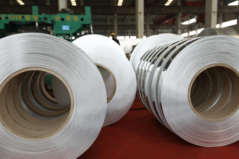
Bare aluminum foil rapidly forms a dense native aluminum oxide (Al₂O₃) layer (2–10 nm thick) upon atmospheric exposure. While this oxide layer provides excellent corrosion resistance, it simultaneously exhibits extremely high electrical resistivity (> 10¹⁴ Ω·cm), resulting in significantly increased contact resistance and reduced solderability. Therefore, surface treatment of HEV aluminum foil is a mandatory process step. Primary approaches include: chemical passivation (e.g., chromate passivation, Cr-free titanium-zirconium-based passivation) forming a dense oxide film of 50–200 nm thickness; electroplated tin (Sn, 1–5 µm thick) to enhance solderability and oxidation resistance—applied as a pre-plating layer prior to laser welding of foil ends; electroplated nickel (Ni, 1–3 µm thick) serving as a diffusion barrier and corrosion-resistant layer; electroplated copper (Cu, 1–3 µm thick) acting as an intermediate layer for Al-Cu transition joints to suppress brittle Al-Cu intermetallic compound (IMC) formation; and organic solderability preservative (OSP) coating providing short-term oxidation protection. Notably, aluminum foil surface treatment is more challenging than copper foil treatment—the native aluminum oxide layer is exceptionally difficult to remove and requires specialized pretreatment processes (e.g., fluoride activation, zincate displacement, nickel flash plating) to achieve reliable solderability.
Mechanical Properties and Temper Processing
Aluminum foil mechanical properties are jointly governed by alloy grade, temper condition, grain size, and annealing parameters. Common tempers include O (annealed, elongation ≥ 30 %), H12 (¼-hard), H14 (½-hard), H16 (¾-hard), and H18 (full-hard, tensile strength 130–200 MPa). HEV hairpin aluminum foil windings typically employ H12 or H14 tempers to balance bend formability and mechanical strength; the O temper is primarily used for battery tab and busbar applications requiring complex bending. Aluminum’s elastic modulus (69 GPa) is ~63 % that of copper (110 GPa), leading to greater elastic deformation under equivalent stress and rendering hairpin end-forming springback control more difficult. Aluminum’s CTE (23×10⁻⁶ /K) is substantially higher than that of copper (16.5×10⁻⁶ /K) and silicon steel laminations (11–13×10⁻⁶ /K), posing a severe challenge under high-power-density thermal cycling conditions in HEV motors—the CTE mismatch stress between aluminum foil windings and insulation layers, and between aluminum foil windings and silicon steel laminations, is ~50 % higher than that of copper foil windings, constituting a critical driver of thermo-mechanical fatigue failure.
Key Performance Indicator System
Conductivity and Skin Effect
The electrical conductivity of aluminum foil is the most critical parameter for its application as a conductive material. The volume resistivity of 1050-O aluminum foil is approximately 2.82×10⁻⁸ Ω·m, equivalent to 61 % IACS. Relative to copper (1.72×10⁻⁸ Ω·m, 101 % IACS), aluminum exhibits approximately 60 % of copper’s conductivity; thus, to achieve equivalent current-carrying capacity, the cross-sectional area of aluminum foil must be increased to approximately 1.67 times that of copper foil. This area compensation in hybrid electric vehicle (HEV) motor design is typically realized by widening the aluminum hairpin (e.g., from 4–10 mm for copper hairpins to 8–16 mm for aluminum hairpins) and increasing its thickness (e.g., from 1–3 mm for copper hairpins to 2–4 mm for aluminum hairpins). The skin depth δ = √(2ρ/(ωμ)) for pure aluminum is approximately 0.83 mm at 10 kHz and ~0.26 mm at 100 kHz; therefore, HEV hairpin aluminum foil windings commonly adopt a thickness of 2–4 mm to ensure controllable skin effect at low frequencies, whereas high-frequency applications (>100 kHz), such as on-board charger (OBC) planar transformers, typically employ thin aluminum foil (0.1–0.3 mm) paired with high-frequency magnetic cores. Another critical design challenge arising from the skin effect is aluminum’s heightened sensitivity to high-frequency resistance—aluminum’s magnetic permeability approximates that of vacuum, yet its resistivity is ~64 % higher than copper’s, resulting in significantly increased high-frequency AC impedance. This necessitates consideration of aluminum foil parallelization (e.g., Litz-type aluminum foil structures) in process design to minimize AC losses.
Thermal Conductivity and Temperature Rise Control
Aluminum’s thermal conductivity ranges from 205–235 W/(m·K), lower than copper’s (391–401 W/(m·K)) but substantially superior to most insulating materials (polyimide film: 0.1–0.35 W/(m·K); epoxy resin: 0.2–0.5 W/(m·K)), establishing it as a key thermal conduction pathway in HEV motor windings. Typical power density for hybrid electric drive motors is 4–10 kW/kg (compact belt-driven starter generators (BSG) reach 15–25 kW/kg), rendering temperature rise control more challenging than in battery electric vehicle (BEV) motors—due to the densely packed engine bay housing the internal combustion engine, transmission, and motor simultaneously. Aluminum hairpin winding temperature rise control relies on: ① slot fill factor enhancement to 65–75 % (20–30 percentage points higher than round enameled wire’s 40–50 %); ② direct cooling channels (water-cooled jackets, common in Toyota THS-II / Honda i-MMD third-generation drive motors); and ③ high-thermal-conductivity insulating varnishes (e.g., polyimide or amide-imide varnishes) to strengthen the thermal conduction path from aluminum foil to insulation layer. In BSG applications, extremely high motor power density (>15 kW/kg) combined with frequent start-stop operation (up to 30–60 cycles per hour) subjects windings to severe thermal cycling; thus, winding temperature rise must be controlled within 110 K (Class B) or 130 K (Class F).
Mechanical Strength and Vibration Durability
HEV motors endure engine-bay vibration (5–500 Hz, RMS acceleration 1.0–4.0 g—significantly exceeding BEV motor levels of 0.5–2.0 g), high-frequency transmission shock (typical 1000–5000 Hz, peak 5–15 g), and random road-induced vehicle vibration. Aluminum foil exhibits lower mechanical strength than copper foil (tensile strength of H14 aluminum foil: 110–150 MPa vs. 250–300 MPa for equivalent-state copper foil); however, alloying (e.g., 3003/5052 alloys) and temper control (e.g., adoption of high-strength H18/H19 tempers) can elevate tensile strength to 180–220 MPa. HEV aluminum foil windings must pass IEC 60034-1 and IEC 61373 vibration testing: random vibration (5–200 Hz, RMS 0.75–2.58 g) and half-sine shock (30 ms, peak 5–10 g), with no insulation damage, inter-turn short circuits, or winding loosening post-test. Aluminum foil fatigue behavior warrants special attention: pure aluminum exhibits a fatigue limit of ~30–50 MPa at 10⁷ cycles—only 25–35 % of its tensile strength. Microcracks formed during aluminum hairpin end-forming may propagate under prolonged vibration, representing one of the most common failure modes in HEV aluminum foil windings.
Weldability and Interconnection Process Compatibility
Aluminum foil interconnection processes differ significantly from those for copper foil. While copper foil permits mature joining techniques—including brazing, laser welding, resistance welding, and ultrasonic welding—aluminum foil requires specially engineered processes due to its native oxide layer, brittle Al-Cu intermetallic compounds (IMCs), and coefficient-of-thermal-expansion (CTE) mismatch. Primary processes include: ① Ultrasonic welding (USW, 20–40 kHz, pressure 1–5 kN)—high-frequency vibration fractures the Al₂O₃ layer to enable solid-state Al-Al bonding; this is the predominant method for HEV aluminum hairpin end connections; ② Laser welding (argon-shielded atmosphere, power 1–4 kW)—primarily used for aluminum foil busbar-to-aluminum busbar connections; ③ Friction stir welding (FSW)—employed for thick aluminum foil (3–8 mm) connections, applied in large HEV drive motor stator windings; ④ Capacitor discharge welding / projection welding—for rapid aluminum foil-to-aluminum terminal connections; and ⑤ Brazing (aluminum-based filler metals, melting point 580–620 °C)—used for Al-Cu transition joints. The brittleness of IMCs formed during direct Al-Cu welding (e.g., Al₂Cu, AlCu, Al₄Cu₉) constitutes a key technical challenge in HEV aluminum foil applications—these IMCs exhibit extremely poor mechanical properties (high hardness, high brittleness) and significantly degrade both electrical and thermal conductivity. Mitigation strategies include: ① Insertion of a nickel interlayer between Al and Cu to form an Al-Ni-Cu triple-layer structure, suppressing direct Al-Cu diffusion; ② Pre-plating aluminum foil with nickel or copper prior to welding with copper foil; and ④ Hybrid ultrasonic welding + low-temperature brazing to achieve high-strength joints at reduced temperatures.
Typical Application Scenarios of Aluminum Foil in Hybrid Electric Vehicle Motors
Hairpin Aluminum Foil Windings for Hybrid Drive Motors
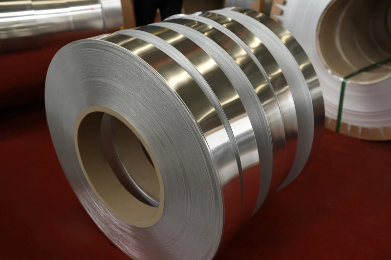
Modern hybrid electric vehicle (HEV) drive motors—such as the Toyota THS-II Gen 4 1.5L/1.8L system, Honda i-MMD Gen 3 2.0L system, and BYD DM-i 1.5L/1.5T Xiao Yun high-thermal-efficiency engine–matched motors—are rapidly transitioning to hairpin-shaped flat-wire winding technology, with increasing exploration of aluminum hairpin windings. Compared to conventional round enameled wire windings (slot fill factor: 40–50 %), hairpin flat-wire windings achieve slot fill factors of 65–80 %, boosting power density by 15–25 %. Advantages of aluminum hairpin windings over copper hairpin windings include: ① weight reduction of 50–55 % (aluminum density is ~30 % that of copper by volume; after cross-sectional area compensation, actual weight reduction remains >50 %); ② cost reduction of 40–60 % (aluminum price is ~1/3 that of copper); ③ resource sustainability (aluminum crustal abundance ~8 % vs. copper ~0.007 %). Key challenges for aluminum hairpin windings include: ① cross-sectional area compensation (typical aluminum hairpin dimensions: width 8–16 mm, thickness 2–4 mm; typical copper hairpin dimensions: width 4–10 mm, thickness 1–3 mm); ② end-turn forming springback control (low elastic modulus of aluminum results in large springback after bending); ③ end-turn joining process (aluminum hairpin end joining is more complex than copper, primarily employing hybrid ultrasonic welding + laser welding). Currently, mainstream HEV drive motors still predominantly use copper hairpin windings (e.g., Toyota THS-II Gen 4 drive motor), though certain PHEV systems—including select BYD DM-p AWD models and specific motors within Great Wall Motors’ Hi4 architecture—have piloted aluminum hairpin winding solutions, mainly for low-power auxiliary drive applications.
Generators and ISG/BSG Starter-Generators in Hybrid Systems
Generators in hybrid systems—typically rated 30–80 kW (e.g., Toyota THS MG1 generator, Honda i-MMD generator motor, Great Wall Hi4 P2 generator)—and belt-driven starter-generators (BSG) or integrated starter-generators (ISG) (rated 10–20 kW in 48 V systems; 30–50 kW in 288 V systems) represent key application areas for aluminum foil windings. Generator windings typically employ distributed short-pitch configurations, imposing lower hairpin process requirements than drive motors; thus, aluminum foil adoption faces fewer barriers here than in drive motors. BSG/ISG starter-generators demand extremely high power density (>15 kW/kg), very high start-stop cycling frequency (30–60 cycles/hour), and wide operating temperature range (−40 °C to +155 °C). Aluminum foil windings must therefore meet: ① high mechanical strength (to withstand frequent start-stop shock loads); ② low resistivity (for high-power output); ③ excellent vibration durability; ④ reliable end-turn connections (fatigue resistance under start-stop shock loading). 48 V BSG starter-generators—such as mainstream products from Tier 1 suppliers Bosch, Valeo, and Continental—have begun large-scale adoption of aluminum foil windings; aluminum hairpin processing for 48 V BSGs is now relatively mature, with aluminum foil usage expanding across thicknesses of 0.5–2.0 mm.
Aluminum Busbars and Battery Module Interconnections
High-current interconnection systems are required within HEV high-voltage battery modules, between modules and battery packs, and between battery packs and electric drive assemblies; busbars constitute critical connection components. Typical HEV high-voltage busbar operating currents range 200–600 A, with system voltages of 144 V, 288 V, or >400 V for PHEVs. Compared to copper busbars (density 8.96 g/cm³), aluminum busbars (density 2.70 g/cm³) reduce weight by 60–70 %, making them a key lightweighting solution for HEVs. Common aluminum grades used for busbars include 1050, 1060, and 1350, with thicknesses of 1.0–4.0 mm and widths of 20–80 mm; surfaces are typically coated with insulating films (polyimide film, PVC film, heat-shrink tubing) to satisfy insulation and creepage distance requirements. Aluminum foil used for cell-to-cell interconnections inside battery modules (“aluminum tabs” or “aluminum connecting strips”) commonly employs grades 1060 or 1070, with thicknesses of 0.5–2.0 mm and widths of 10–30 mm; surfaces are nickel-plated or tin-plated to enhance solderability and corrosion resistance. Critical consideration: galvanic corrosion at direct Al–Cu interfaces—direct contact between aluminum and copper in humid environments induces galvanic corrosion (electrochemical potential difference ~0.65 V), accelerating aluminum degradation. Mitigation strategies include: ① inserting stainless steel shims or nickel transition layers between Al and Cu; ② nickel-plating aluminum surfaces prior to Cu–Al jointing; ③ using copper–aluminum transition joints (CUAL or bi-metal joints). GB/T 3190 and ISO 209 impose strict requirements on chemical composition and mechanical properties of battery-pack aluminum foils.
Aluminum Foil Windings in Power Electronics and Planar Transformers for Hybrid Vehicles
Power electronic devices in HEVs—including motor inverters, DC–DC boost/buck converters, on-board chargers (OBCs, applicable only to PHEVs and HEVs), and air-conditioning compressor drivers—are rapidly adopting SiC (silicon carbide) power devices. Inverter switching frequencies have increased from traditional IGBT levels of 5–15 kHz to SiC-based frequencies of 50–200 kHz. At such high switching frequencies, planar transformers are increasingly adopted—offering advantages over conventional wound transformers including low profile, high power density, low leakage inductance, and superior thermal management. Planar transformer windings commonly employ copper or aluminum foil (thickness 0.05–0.5 mm). Relative to copper foil, aluminum foil offers significant cost advantages (aluminum price ~1/3 that of copper, with cost differential widening as foil thickness increases) and weight advantages (aluminum planar transformers weigh ~60 % less than equivalent copper units). Aluminum foil planar transformers are now widely deployed in HEV 48 V DC–DC converters (stepping up to 12 V or 16 V for low-voltage systems); some 400 V architecture PHEV OBCs have also begun trialing aluminum foil windings. Key challenges for aluminum foil planar transformers include: ① high-frequency skin effect (skin depth only 0.26 mm at 100 kHz) → strict aluminum foil thickness control required; ② Al–Cu intermetallic compound (IMC) formation at aluminum winding–copper lead terminations; ③ combined skin and proximity effect losses; ④ uniformity of insulating enamel coating. Aluminum foil planar transformers must pass standard qualification tests including IPC-9701 (printed board reliability) and AEC-Q200 (automotive passive component reliability).
Aluminum Foil Manufacturing Processes
Rolled Annealed (RA) Process Route
The primary manufacturing process for hybrid electric vehicle (HEV) aluminum foil is the Rolled Annealed (RA) route, which resembles the copper foil RA route but features significantly different process parameters: ① Raw material—aluminum ingots (grades 1050, 1060, 1350, etc., thickness 10–20 mm); ② Hot rough rolling—temperature 350–500 °C (substantially lower than copper’s 700–950 °C), pass reduction 30–60 %; ④ Multiple cold rolling passes with intermediate annealing—annealing temperature 300–400 °C (reflecting aluminum’s lower recrystallization temperature); ⑤ Final cold rolling to finished thickness (0.05–8.0 mm); ⑥ Cleaning, final annealing, tempering, and slitting. Aluminum foil produced via the RA process exhibits low anisotropy, high elongation (O-temper ≥ 30 %), and uniform mechanical properties, making it the dominant process for HEV hairpin aluminum foil, BSG aluminum foil windings, and aluminum busbars. Key process control parameters include mill precision, tension control, strip flatness control, and annealing furnace atmosphere (bell-type annealing furnaces utilize nitrogen protective atmosphere).
Continuous Casting and Rolling & Conform Continuous Extrusion
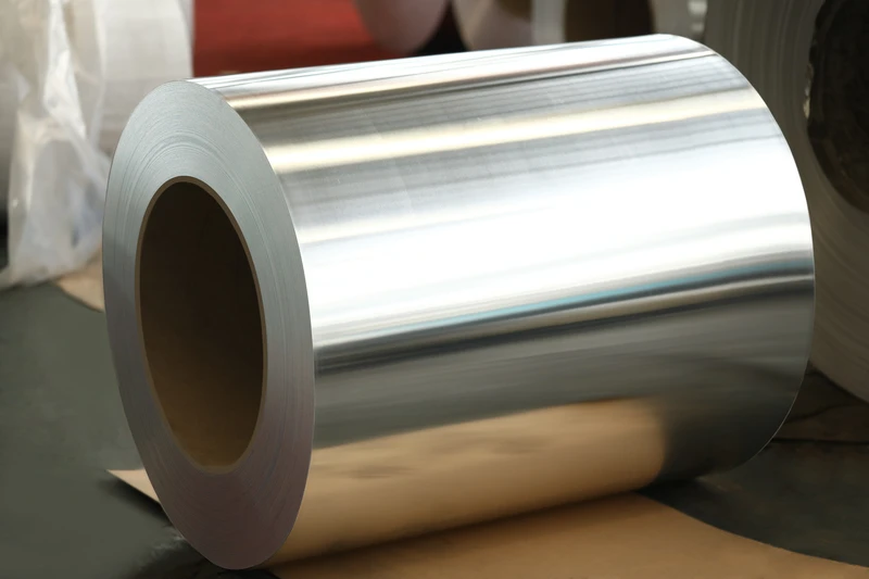
For large-cross-section aluminum foil (thickness 3.0–8.0 mm, width 8–16 mm) required to meet HEV hairpin cross-sectional area demands, continuous casting and rolling and Conform continuous extrusion processes have been progressively adopted: ① Continuous casting and rolling—molten aluminum is continuously solidified into aluminum rods, then rolled into finished flat aluminum strips via a tandem rolling mill; energy consumption is reduced by 30–50 %, coil lengths reach several kilometers, and grain structure is fine and uniform; ② Conform continuous extrusion—enables near-net-shape forming of profiled aluminum bars and high-precision flat aluminum strips, already deployed in select European HEV traction motor production lines (e.g., Tier 1 suppliers such as Bosch and Remy).
Surface Treatment and Insulation Cladding
HEV aluminum foil surface treatment typically comprises: ① Degreasing—alkaline or acidic degreasing to remove rolling oil; ② Micro-etching—acidic or alkaline micro-etching to remove the native oxide layer; ③ Passivation—chromate or chromium-free passivation (titanium-zirconium based) to form a dense protective film; ④ OSP coating—organic solderability preservative film, thickness 0.1–0.3 µm, providing 6–12 months storage protection; ⑤ Electroplating—tin, nickel, copper, silver, etc., applied per application requirements. Critical control points on the surface treatment line include film uniformity (thickness variation ≤ ±20 %), adhesion (cross-hatch test ≥ 4B rating), solderability (IPC J-STD-002 test ≥ 95 % wetting ratio), and corrosion resistance (neutral salt spray test ≥ 96 h without red rust). Some HEV aluminum foils are supplied with pre-applied insulation cladding—polyimide (PI) film or mica tape thermally laminated to the foil, yielding an integrated “aluminum foil + insulation” semi-finished product enabling direct use in winding formation by motor manufacturers.
Slitting, Stamping, and Winding Formation
Finished aluminum foil is slit into narrow strips (tolerance ≤ ±0.05 mm), then fed into progressive stamping dies to produce hairpin U-shaped components or rotor bar blanks, followed by bending, twisting, and end-forming to complete the winding assembly. A typical HEV hairpin aluminum foil winding formation sequence is: flat aluminum strip unwinding → leveling → progressive stamping of U-shaped parts → insertion of U-shaped parts into stator slots → end expansion (twisting + flaring) → end joining (ultrasonic welding + laser welding) → VPI (vacuum pressure impregnation) or resin casting. VPI employs epoxy or polyester resin under vacuum and pressure; the impregnating varnish system must comply with EN 45545-2 HL3 fire protection and low-smoke, low-toxicity requirements (particularly stringent for HEV vehicle-level fire safety). For HEV aluminum hairpin end joining, dual-pulse fiber laser welding and ultrasonic welding are the predominant processes; laser welding speed exceeds 50 mm/s, with narrow heat-affected zone (HAZ) and excellent repeatability; ultrasonic welding is suitable for rapid joining of thinner aluminum foils (0.5–2.0 mm).
Quality Inspection and Reliability Validation
Electrical, Mechanical, and Thermal Performance Test Standards
HEV aluminum foil quality inspection covers five dimensions: electrical, mechanical, thermal, chemical, and surface properties. Electrical testing includes DC resistivity (per ASTM B193 or IEC 60028), AC impedance and skin-effect resistance (per IPC TM-650 2.5.5), and insulation dielectric withstand voltage (per ASTM D149). Mechanical testing includes tensile strength and elongation at break (per ASTM E8), bending fatigue life (per ASTM E796), and hardness (per ASTM E384). Thermal testing includes thermal conductivity (per ASTM E1461 laser flash method), coefficient of thermal expansion (CTE) (per ASTM E228), and thermal cycling durability (per IPC-9701). Surface testing includes surface roughness (per ISO 4287), coating thickness (per ASTM B568 X-ray fluorescence method), and solderability (per IPC J-STD-002). Supplementary tests specific to HEV operating conditions include motor winding temperature rise testing (per IEC 60034-1), vibration and shock testing (per IEC 61373), and automotive-grade reliability testing (per AEC-Q100/Q200).
Automotive-Grade Standards and Material Compliance Requirements
Final acceptance of HEV aluminum foil must comply with automotive-grade industry standards and material compliance requirements. Automotive quality management system standards include IATF 16949 (Automotive Quality Management Systems) and AIAG PPAP (Production Part Approval Process). Automotive electronic component reliability standards include AEC-Q100 (Stress Test Qualification for Integrated Circuits) and AEC-Q200 (Stress Test Qualification for Passive Components). Environmental compliance standards include RoHS 2.0 (Restriction of Hazardous Substances), REACH (Registration, Evaluation, Authorisation and Restriction of Chemicals), ELV (End-of-Life Vehicles Directive 2000/53/EC), and GB/T 26572 (Restriction of Hazardous Substances in Electrical and Electronic Products in China). Battery-related standards include GB 38031 (Safety Requirements for Traction Batteries Used in Electric Vehicles), UN 38.3 (Safety Testing for Lithium Batteries During Transport), and UL 1973 (Standard for Safety for Stationary Batteries). Typical hazardous substance content limits for HEV aluminum foil are: Pb < 1000 ppm, Cd < 100 ppm, Hg < 100 ppm, Cr⁶⁺ < 1000 ppm, PBB < 1000 ppm, PBDE < 1000 ppm (RoHS 2.0), and SVHC (168 substances of very high concern) < 0.1 % by weight (REACH).
Long-Term Reliability and Lifetime Prediction
The design service life of HEV vehicles is typically 10–15 years or 250,000–300,000 km, corresponding to 8,000–15,000 operating hours for HEV motor windings. Aluminum foil windings experience coupled electrical, thermal, mechanical, and environmental stresses during long-term operation: Under electrical stress, high dv/dt pulses from motor controllers (typical 5–10 kV/µs) induce partial discharge (PD) in turn-to-turn insulation, causing cumulative insulation aging; under thermal stress, thermal cycling induced by frequent start-stop cycles, acceleration, and hill climbing causes thermomechanical fatigue between aluminum foil windings and insulation layers (CTE mismatch stress is particularly severe—aluminum foil exhibits 30–50 % higher fatigue failure risk than copper foil); under mechanical stress, engine bay vibration, transmission shock, and random road vibration cause loosening of aluminum foil winding ends and slot sections (low elastic modulus of aluminum results in inferior anti-loosening performance); under environmental stress, temperature-humidity cycling from −40 °C to +85 °C, engine oil vapor, coolant evaporation products, and brake dust accelerate corrosion-induced degradation of both insulation and aluminum foil. Reliability validation of HEV aluminum foil windings requires completion of full type testing (per IEC 60034-1, IEC 61373, and AEC-Q100/Q200), supplemented by lifetime prediction using the Arrhenius thermal aging model and cumulative damage modeling (Miner’s Rule). Aluminum-specific failure modes include: ① Al–Cu intermetallic compound (IMC) growth leading to increased contact resistance and mechanical embrittlement (IMC growth rate accelerates exponentially with temperature); ② pitting corrosion on aluminum surfaces (in corrosive media such as Cl⁻ and SO₄²⁻); ③ propagation of micro-cracks at aluminum hairpin end-forming locations under long-term vibration; ④ delamination at the aluminum–insulation interface (due to CTE mismatch stress). These failure modes must be mitigated during design through material selection, process optimization, and insulation system design, and validated via accelerated aging tests (e.g., 85 °C/85 % RH high-temperature/high-humidity test + 1000 hours) and HALT (Highly Accelerated Life Testing).
Conclusion
The selection of aluminum foil for hybrid electric vehicle (HEV) motors is a multidimensional engineering decision encompassing material purity (1xxx-series pure aluminum, 3xxx-series Al-Mn, 5xxx-series Al-Mg), surface treatment (passivation, OSP, tinning, nickel plating, copper plating), temper (O, H12, H14, H16, H18), thickness (0.05–8.0 mm), insulation system (polyimide film, mica tape, epoxy VPI, ceramic coating), and manufacturing process (RA, continuous casting and rolling, Conform). Across four typical application families—HEV traction motor hairpin aluminum foil windings, HEV generators and BSG/ISG starter-generators, aluminum foil busbars and battery module interconnections, and power electronics and planar transformers—the aluminum foil must simultaneously satisfy comprehensive multi-dimensional requirements: high electrical conductivity (≥ 61 % IACS), lightweighting (density 2.70 g/cm³), high mechanical strength (tensile strength ≥ 110 MPa), high corrosion resistance (96 h neutral salt spray test), vibration durability (IEC 61373), thermal endurance (IEC 60034-1 Class B/F/H), automotive-grade compliance (IATF 16949, RoHS 2.0, REACH, ELV), and long-life reliability (10–15 years). As HEVs evolve toward higher efficiency (>40 % internal combustion engine thermal efficiency), greater integration (motor-transmission integration), high-voltage architectures (800 V platforms), and SiC-based power electronics, requirements for aluminum foil—specifically electrical conductivity, lightweighting, CTE matching, Al-Cu intermetallic compound (IMC) control, and high-frequency capability—will further intensify. Next-generation HEV aluminum foil technology trends may include: ① copper-clad aluminum (CCA) composite foil—combining copper’s high conductivity with aluminum’s lightweight advantage; ② higher-strength Al-Mg-Si alloys (e.g., 6xxx-series 6061, 6111) for hairpin aluminum foil windings; ③ Al₂O₃ ceramic-coated aluminum foil—maintaining insulation stability at elevated temperatures (>200 °C); and ④ intelligent production lines integrating aluminum foil processing with AI-powered vision inspection—utilizing machine vision to monitor hairpin end-forming quality and end-connection quality in real time—thereby reinforcing aluminum foil’s position as the core lightweight conductive material in HEV electric drive systems.