


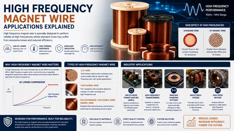
High frequency magnet wire is a specialty enameled winding wire that maintains low AC resistance and low losses in the 20 kHz to 30 MHz frequency range. Compared with power frequency (50/60 Hz) magnet wire, high frequency magnet wire must address the reduction in effective conductor cross-section and the surge in eddy current losses caused by the skin effect and the proximity effect. This has driven the formation of an independent engineering system covering conductor structure, single-strand diameter, stranding configuration, and insulation enamel film.
The core physical problem of high frequency magnet wire can be summarized by the skin depth formula: in 25°C copper conductors, the skin depth is only 0.21 mm at 100 kHz, 0.066 mm at 1 MHz, and 0.021 mm at 10 MHz. This means that in the MHz frequency range, current flows only in a thin layer of about 20 μm on the conductor surface, while the conductor interior barely contributes to current conduction. If Φ0.50–2.00 mm single-strand enameled round wire commonly used for power frequency continues to be used, the obvious “hollow effect” appears — wasted material and additional AC losses.
To address this physical limitation, four major product families of high frequency magnet wire have evolved: single-strand fine enameled wire (suitable for 20–100 kHz), stranded wire (100 kHz–1 MHz), Litz wire (100 kHz–30 MHz), and copper foil / aluminum foil / braided wire (MHz-grade planar windings). These four categories form the basic materials for key applications such as wireless charging, induction heating, switching power supplies, RFID, medical imaging, and new energy vehicles.
This guide systematically discusses the physics foundation, product types, application areas, selection methods, and quality control of high frequency magnet wire from five dimensions, aiming to provide complete engineering reference for high frequency magnetic component design engineers, winding process engineers, and electrical procurement engineers.
Physics Foundation and Frequency Banding of High Frequency Magnet Wire
Skin Effect and Skin Depth Formula
The skin effect is the most fundamental physical phenomenon in high frequency magnet wire engineering. When AC current flows through a conductor, eddy currents are induced inside the conductor. The eddy currents superimpose on the main current and force it to concentrate on the conductor surface. The skin depth is defined as the depth at which the current density decays to 1/e (about 36.8%) of the surface value, given by the formula:
δ = √(ρ / (π·f·μ))
where δ is the skin depth (m), ρ is the electrical resistivity (Ω·m), f is the frequency (Hz), and μ is the magnetic permeability (H/m).
In 25°C pure copper (ρ = 1.724×10⁻⁸ Ω·m, μ ≈ μ₀ = 4π×10⁻⁷ H/m), the reference skin depths at different frequency bands are as follows:
| Frequency | Skin Depth δ (mm) | Engineering Impact |
|---|---|---|
| 50 Hz | 9.33 | Large cross-section single-strand round wire: no impact |
| 1 kHz | 2.09 | Φ2.0 mm wire still usable |
| 10 kHz | 0.66 | Φ0.50 mm wire begins to show hollow effect |
| 100 kHz | 0.21 | Multi-strand stranding required |
| 1 MHz | 0.066 | Litz wire required |
| 10 MHz | 0.021 | Braided wire / copper foil required |
| 100 MHz | 0.0066 | Silver-plated surface / skin-layer dedicated |
Engineering experience: when the skin depth is less than half the conductor radius, the ratio of AC resistance to DC resistance (ACF) begins to rise significantly; when the skin depth is less than one-third, the conductor selection must switch to Litz structure or multi-strand configuration.
Proximity Effect and Stranding Strategy
The proximity effect refers to the mutual induction of eddy currents between currents in adjacent conductors, leading to further reduction of the effective current-carrying area. In tightly wound coils (such as concentric multi-layer windings), the proximity effect is usually more severe than the skin effect, with losses reaching 2–3 times that of the skin effect.
To suppress the proximity effect, engineering strategies include:
- Multi-strand stranding (Litz structure): split the large cross-section conductor into multiple fine strands, and transposition them at precise pitch so that each strand takes turns occupying the inner and outer positions of the winding.
- Optimized winding distribution: avoid tight multi-layer stacking, use sectional bobbins or flat coils.
- Controlled pitch: pitch ≤ 8 times the single-strand diameter, ensuring magnetic field integration minimization.
- Selected braid angle: the optimal braid angle for braided Litz wire is 30°–60°; outside this range, losses rise by 15%–30%.
Engineering experience: in the 100 kHz–1 MHz band, the proximity effect loss of standard Litz wire (5 strands × 0.04 mm) is 60%–80% lower than that of a solid round wire with the same cross-section.
Frequency Banding and Magnet Wire Type Correspondence
According to mainstream engineering practice, the correspondence between high frequency bands and magnet wire types is as follows:
| Frequency Band | Frequency Range | Recommended Magnet Wire Type | Typical Single-Strand Diameter |
|---|---|---|---|
| Audio | 20 Hz–20 kHz | Single-strand enameled round wire | Φ0.30–1.00 mm |
| Low High Frequency | 20–100 kHz | Fine single-strand / multi-strand | Φ0.10–0.50 mm |
| Mid High Frequency | 100 kHz–1 MHz | Litz wire (Type 2/3) | Φ0.05–0.20 mm |
| High High Frequency | 1–10 MHz | Litz wire (Type 4/5) | Φ0.025–0.10 mm |
| Very High Frequency | 10–30 MHz | Braided wire / silver-plated copper foil | Φ0.020–0.05 mm |
| Ultra High Frequency | > 30 MHz | Coaxial / microstrip / planar coil | — |
Note: Litz wire Types 1–6 are defined by ASTM B-286, and the higher the Type number, the more stranding layers and the higher the applicable frequency range.
Core Product Types of High Frequency Magnet Wire
Single-Strand Fine Enameled Round Wire
Single-strand fine enameled round wire is the most basic form of high frequency magnet wire, with diameter range typically Φ0.05–0.50 mm, between power frequency magnet wire (Φ0.20–3.00 mm) and ultra-fine enameled wire (Φ0.012–0.05 mm).
Main Application Scenarios:
- SMPS high frequency transformers below 100 kHz
- Audio transformers (such as tube output transformers, microphone inductors)
- Small high frequency inductors for home appliances (rice cooker control boards, LED drivers)
- Small high frequency inductors for industrial control
Technical Features:
- Insulation enamel film: polyurethane (UEW), polyester (PEW), polyesterimide (EIW), polyamide-imide (AIW)
- Enamel thickness: Grade 1 (10–25 μm), Grade 2 (25–40 μm), Grade 3 (>40 μm)
- Breakdown voltage: Grade 1 ≥ 1.8 kV, Grade 2 ≥ 2.5 kV
- Resistance tolerance: ±2%–5% (per IEC 60317-0-1)
- Thermal class: Class 130 (UEW/PEW), Class 155 (PEW/EIW), Class 180 (EIW/AIW), Class 200 (AIW)
Multi-Strand Enameled Bunched Wire
Multi-strand enameled bunched wire is formed by twisting multiple fine enameled wires in S-twist or Z-twist direction, with strand count typically 3–60. The stranding structure is simple with good flexibility, suitable for the 20 kHz–1 MHz band.
Main Application Scenarios:
- Mid-frequency induction heating (30–100 kHz)
- Medium-power wireless charging (85–205 kHz)
- Communication power supply filters (100 kHz–1 MHz)
- Industrial inverter output filters
Technical Features:
- Twist direction: S-twist (counterclockwise), Z-twist (clockwise)
- Pitch length: ≤ 60 mm, conforming to IEC 60317-0-11
- Single-strand diameter: Φ0.05–0.20 mm
- Strand count: 3–60 strands (standard: 7, 10, 15, 20, 30, 40, 50, 60)
- Twist direction impact: noise-sensitive applications (such as inductors) require specified direction to avoid magnetic field coupling
Litz Wire
Litz wire is the core product of high frequency magnet wire, made by twisting multiple independently insulated fine enameled wires at precise pitch and symmetric structure. ASTM B-286 divides Litz wire into six Types 1–6:
| Type | Structural Feature | Applicable Frequency Band |
|---|---|---|
| Type 1 | Single-layer stranding | 100 kHz–1 MHz |
| Type 2 | Multi-layer stranding (concentric) | 100 kHz–2 MHz |
| Type 3 | Double insulation + single-layer stranding | 100 kHz–3 MHz |
| Type 4 | Double insulation + multi-layer stranding | 1–5 MHz |
| Type 5 | Triple insulation + multi-layer stranding | 1–10 MHz |
| Type 6 | Braided type | 5–30 MHz |
Main Application Scenarios:
- Wireless charging transmitter coils (Qi 100–205 kHz)
- Electric vehicle wireless charging (85 kHz SAE J2954)
- Induction heating furnaces (30–100 kHz industrial grade)
- MRI gradient coils (kHz-grade high current)
- 5G base station resonant inductors
Technical Features:
- Single-strand diameter: AWG 36–48 (Φ0.127–0.04 mm)
- Strand count: 10–1500 strands
- Single-strand insulation: polyurethane (UEW) or polyesterimide (EIW)
- Pitch: ≤ 8 × single-strand diameter
- Braid angle: 30°–60°
- Working temperature: Class 130–200 (depending on insulation enamel)
Braided Wire, Copper Foil, and Planar Windings
Braided wire is made by cross-weaving multiple fine copper wires, suitable for frequencies above 5 MHz. Copper foil and aluminum foil are used for MHz-grade planar transformers and planar inductors.
Main Application Scenarios:
- 5G communication resonant cavities
- Satellite communication power combiners
- Radar T/R modules
- High frequency SMPS planar transformers
- High-power LED driver inductors
Technical Features:
- Braided wire: single strand Φ0.05–0.20 mm, braid strand count 16–256
- Copper foil: thickness 0.025–0.20 mm, width 5–50 mm
- Aluminum foil: thickness 0.030–0.30 mm, width 5–80 mm (suitable for lightweight applications)
- Insulation: edge insulation enamel film, polyimide film, epoxy coating
- Working frequency: 5 MHz–GHz grade
Wireless Charging and Induction Heating Applications
Wireless Power Transfer
Wireless charging is one of the most important application areas of high frequency magnet wire. Mainstream standards and frequency bands:
- Qi standard (consumer electronics): 100–205 kHz (typical 110–205 kHz), power 5–15 W
- AirFuel resonant standard: 6.78 MHz, power up to 50 W
- SAE J2954 (electric vehicle WPT): 85 kHz, power 3.3–22 kW
- IEC 61980 (EV WPT international standard): 85 kHz (Band 1), 150–200 kHz (Band 2)
Core requirements of wireless charging on magnet wire:
- High Q factor: coil Q value typically required 50–200
- Low AC resistance: ACF ≤ 1.2 in working frequency band
- High temperature resistance: coil temperature rise of 30–80 K during charging
- High insulation reliability: breakdown voltage ≥ 3 kV (EV applications)
Typical Litz wire selection case (Qi standard 110 kHz):
- Single-strand diameter: Φ0.05 mm (AWG 44) or Φ0.07 mm (AWG 41)
- Strand count: 100–200 strands
- Total cross-section: equivalent to AWG 14–16 single-strand wire
- Q value: 150–250 (reference value)
- ACF: 1.05–1.15 (close to theoretical optimum)
Engineering experience: in the Qi standard 110 kHz working frequency band, Litz 100 × Φ0.05 mm has 50%–70% lower losses than Φ0.50 mm single-strand wire with the same cross-section.
Induction Heating
Induction heating is a traditional industrial application of high frequency magnet wire, with the working frequency band concentrated at 30 kHz–1 MHz:
- Household induction cookers: 20–50 kHz, power 1.5–3.5 kW
- Commercial induction furnaces: 30–100 kHz, power 10–100 kW
- Industrial quenching / through-heating: 100 kHz–1 MHz, power 50 kW to several MW
- Semiconductor zone melting: 200–400 kHz, power 100–500 kW
Requirements of induction heating on magnet wire:
- High saturation temperature resistance: long-term working temperature 180–220°C
- High current carrying capacity: single wire current 50–500 A
- High frequency skin suppression: Litz wire or braided wire required
- Mechanical reliability: vibration resistance, thermal cycling resistance
Typical Litz wire selection case (100 kHz industrial induction heating):
- Single-strand diameter: Φ0.10–0.20 mm
- Strand count: 50–500 strands
- Insulation: polyesterimide (EIW) or polyamide-imide (AIW)
- Braid type: Type 2 or Type 3
- Working temperature: Class 180 or Class 200
Switching Power Supply and Power Electronics Applications
SMPS High Frequency Transformers
Switching power supplies are the largest user of high frequency magnet wire, with the working frequency band 20 kHz–1 MHz, typical value 50–500 kHz.
Main Applications:
- Consumer electronics chargers (mobile phones, laptops): 65–200 kHz
- Server power supplies: 100–500 kHz
- 5G base station power supplies: 500 kHz–1 MHz
- New energy vehicle OBC (on-board charger): 50–200 kHz
- Photovoltaic inverters: 16–100 kHz
- Data center PSU: 500 kHz–2 MHz
Key requirements of SMPS high frequency transformers on magnet wire:
- Low loss: ACF close to 1.0 at working frequency
- High frequency insulation: withstand square wave / trapezoidal wave peaks (dV/dt up to 5–10 kV/μs)
- High temperature resistance: long-term working 130–180°C, hotspots up to 200°C
- Compact winding: high slot fill (>70%) requires fine-diameter magnet wire
Selection Reference:
| Application Scenario | Frequency | Recommended Magnet Wire |
|---|---|---|
| Mobile phone charger | 65–200 kHz | Φ0.10–0.20 mm single-strand / Litz 50 strands |
| Laptop adapter | 100–300 kHz | Φ0.15–0.30 mm single-strand / Litz 100 strands |
| Server power supply | 200–500 kHz | Litz 100–200 strands |
| 5G power supply | 500 kHz–1 MHz | Litz 200–500 strands or copper foil |
| OBC | 50–200 kHz | Φ0.20–0.40 mm single-strand / Litz 100 strands |
PFC Inductors and Common Mode Inductors
Power factor correction (PFC) inductors and common mode inductors (CM Choke) are also important applications of high frequency magnet wire:
- PFC inductors: 50 kHz–500 kHz, working in hard-switching conditions with large current ripple, requiring low-loss magnet wire
- Common mode inductors: 100 kHz–30 MHz, mainly suppressing high frequency common mode noise, requiring broadband high impedance
PFC inductor magnet wire selection:
- 50–100 kHz: Φ0.30–0.50 mm single-strand enameled round wire
- 100–500 kHz: Litz 50–150 strands
- Above 500 kHz: Litz 200–500 strands or copper foil
Common mode inductor magnet wire selection:
- 100 kHz–1 MHz: Φ0.10–0.30 mm single-strand
- 1–10 MHz: Litz 50–100 strands
- 10–30 MHz: Litz 100–300 strands or braided wire
Resonant Inductors and LLC Transformers
LLC resonant converters are the mainstream topology of current high-efficiency power supplies, with working frequency 50 kHz–1 MHz:
- Resonant inductor: single-strand enameled round wire Φ0.20–0.40 mm (50–300 kHz)
- High frequency transformer: Litz 50–300 strands (above 200 kHz)
- Planar transformer: copper foil 0.05–0.15 mm (above 500 kHz)
Engineering experience: 1 MHz LLC converters using Litz 300 × Φ0.05 mm have 25–40°C lower temperature rise compared to Φ0.30 mm single-strand wire.
Communication and Radio Frequency Applications
RFID and NFC
RFID (radio frequency identification) is a niche but important application of high frequency magnet wire:
- Low frequency RFID (LF): 125–134 kHz, mainly for animal identification, access control
- High frequency RFID (HF): 13.56 MHz, mainly for NFC, electronic passports, credit cards
- Ultra-high frequency RFID (UHF): 860–960 MHz, mainly for logistics, retail
RFID coil requirements on magnet wire:
- Precise Q value control (typically 30–80)
- Low parasitic capacitance (avoid too-low self-resonant frequency)
- Stable inductance value (±2%)
13.56 MHz NFC coil selection:
- Single-strand enameled round wire Φ0.10–0.30 mm
- Or Litz 5–20 strands (high-end applications)
- Insulation: polyurethane (UEW) or polyester (PEW)
- Number of turns: 3–7 turns (typical 4 turns)
5G and Satellite Communication
5G communication raises higher requirements for high frequency magnetic components:
- 5G base station power supplies: 500 kHz–1 MHz high frequency transformers, using Litz wire
- Millimeter wave (mmWave): copper foil planar inductors, single-layer coils
- Satellite communication power combiners: braided wire 5–30 MHz
Satellite communication magnet wire:
- Radiation-resistant enamel film (polyimide PAI)
- Vacuum outgassing control (NASA ASTM E595)
- Extreme temperature cycling (-65°C to +200°C)
Radar and Avionics
Military / aviation radar systems have extremely stringent requirements for high frequency magnet wire:
- Working frequency: 1 MHz to several GHz
- Temperature range: -55°C to +250°C
- Vibration / shock resistance: MIL-STD-810
- Radiation resistance: MIL-STD-883
- Enamel film: polyimide (PI), polyamide-imide (AIW)
Radar T/R module magnet wire selection:
- Single-strand Φ0.05–0.20 mm enameled wire
- Copper foil (planar inductor)
- Silver-plated copper wire (ultra-high frequency band)
Medical Imaging and Biomedical Applications
MRI Gradient Coils
MRI (magnetic resonance imaging) systems are the largest medical application of high frequency magnet wire. MRI mainly involves three types of coils:
- Main magnetic field coils (superconducting): DC working, using large cross-section copper wire
- RF coils: MHz grade, using Litz wire
- Gradient coils: kHz-grade high current, using Litz wire
Core requirements of gradient coils on Litz wire:
- Single-strand diameter: Φ0.10–0.30 mm
- Strand count: 100–1000 strands
- Insulation: polyimide (PI) or polyamide-imide (AIW)
- High temperature resistance: above Class 180
- Flame retardant: UL 94 V-0
1.5T MRI gradient coil typical selection:
- Litz 500 × Φ0.10 mm
- Total cross-section 4 mm²
- Current carrying 300–600 A
- Working frequency 1–10 kHz
Radiofrequency Ablation and High Frequency Surgical Equipment
Radiofrequency ablation (RFA) is another important medical application of high frequency magnet wire:
- Working frequency: 375 kHz–500 kHz (typical 480 kHz)
- Power: 50–200 W
- Coil requirements: high Q value, low loss, high insulation reliability
High frequency surgical equipment (electrotomes, ultrasonic scalpels):
- Working frequency: 300 kHz–4 MHz
- Power: 50–300 W
- Coil requirements: medical-grade insulation, low electromagnetic radiation
New Energy Vehicles and Rail Transit Applications
On-Board Charger (OBC) and DC-DC Converters
New energy vehicles (EV) are one of the fastest-growing application areas of high frequency magnet wire:
- OBC (on-board charger): 3.3–22 kW, working frequency 50–200 kHz
- DC-DC converters: 1–5 kW, working frequency 100–500 kHz
- Motor drive inverters: 50–100 kW, switching frequency 5–20 kHz
- Wireless charging: 3.3–22 kW, 85 kHz
OBC high frequency transformer magnet wire selection:
- 7 kW OBC (85 kHz): Litz 100–200 strands
- 11 kW OBC (110 kHz): Litz 200–300 strands
- 22 kW OBC (150 kHz): Litz 300–500 strands
Special requirements for automotive-grade magnet wire:
- AEC-Q200 certification
- IATF 16949 quality system
- Vibration resistance (10–2000 Hz, 10G)
- Temperature cycling resistance (-40°C to +150°C, 1000 cycles)
- Flame retardant grade UL 94 V-0
Traction Motors and Rail Transit
Rail transit traction motors are traditional large users of Litz wire:
- Subway / light rail traction motors: 500 kW–3 MW
- High-speed rail traction transformers: 5–50 MW
- Working frequency: 50 Hz–10 kHz (but switching power supply section reaches 20–100 kHz)
Although the main windings still use large cross-section copper wire, the auxiliary power supplies and control systems use large amounts of high frequency Litz wire.
High Frequency Magnet Wire Selection Methods and Quality Control
Skin Depth and Single-Strand Diameter Selection
Single-strand diameter selection is the first step in high frequency magnet wire selection. Basic rules:
- Single-strand diameter ≤ 2δ (twice the skin depth): ensures uniform current distribution
- Single-strand diameter ≤ 1δ (one skin depth): optimal state, ACF close to 1.0
- Single-strand diameter ≥ 3δ: AC loss surges, should be avoided
Reference design:
| Working Frequency | Skin Depth δ | Recommended Single-Strand Diameter |
|---|---|---|
| 100 kHz | 0.21 mm | Φ0.05–0.10 mm |
| 500 kHz | 0.094 mm | Φ0.025–0.05 mm |
| 1 MHz | 0.066 mm | Φ0.025–0.04 mm |
| 5 MHz | 0.029 mm | Φ0.020–0.030 mm |
Pitch and Strand Count Design
Pitch is the key parameter for Litz wire selection:
- Pitch ≤ 8 × single-strand diameter: standard Litz wire
- Pitch = 4–6 × single-strand diameter: optimal (lowest loss)
- Pitch > 10 × single-strand diameter: skin effect suppression declines, not recommended
Strand count calculation formula:
N = A_total / A_single
where N is the strand count, A_total is the required total cross-section, and A_single is the single-strand cross-section.
In actual design, a 5%–10% safety margin is considered, and the strand count is usually taken as a multiple of 10 for ease of production.
ACF Estimation and Loss Control
The AC resistance factor (ACF) is the core indicator for measuring high frequency magnet wire performance:
ACF = R_ac / R_dc
Below 100 kHz, the ACF of standard Litz wire should be controlled at 1.05–1.20; at 1 MHz, it should be controlled at 1.10–1.30; at 10 MHz, it should be controlled at 1.20–1.50.
Consequences of excessive ACF:
- Coil temperature rise intensifies (for every 10°C increase, insulation life is reduced by 50%)
- Efficiency decreases (for every 1% decrease in high frequency power supply efficiency, several thousand kWh of electrical energy is lost annually)
- System stability decreases (Q value decrease leads to resonant frequency drift)
Insulation Reliability and Enamel Film Selection
High frequency environment poses severe challenges to enamel film insulation:
- Partial discharge: peak voltages of high frequency square waves easily trigger partial discharge
- Dielectric loss: enamel film dielectric loss rises at high frequencies
- Space charge accumulation: space charges under DC bias cause electric field distortion
Enamel film selection principles:
- Working temperature < 130°C: UEW (polyurethane, solderable)
- Working temperature 130–155°C: PEW/EIW (polyester/polyesterimide)
- Working temperature 155–180°C: EIW/AIW (polyesterimide/polyamide-imide)
- Working temperature 180–200°C: AIW/PI (polyamide-imide/polyimide)
- Working temperature > 200°C: PI (polyimide)
Standards System and Certification
International standards system for high frequency magnet wire:
- ASTM B-286: Litz wire and braided conductors (Type 1–6 classification)
- IEC 60317-0-1: General requirements for enameled round copper wire
- IEC 60317-11: Class 130 polyurethane enameled round copper wire
- IEC 60317-0-11: Solderable polyurethane enameled round copper wire (multi-strand)
- NEMA MW 1000: North American enameled wire standard
- GB/T 6109: China enameled wire standard
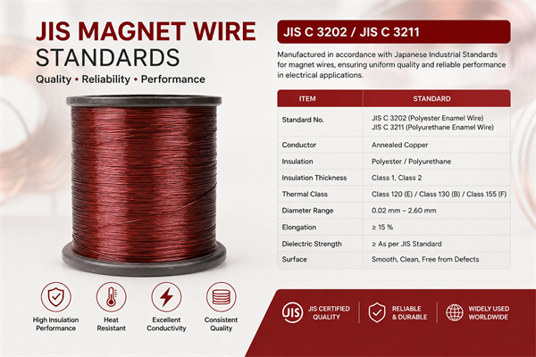
- JIS C 3202: Japan enameled wire standard
Application field standards:
- Qi standard: Wireless Power Consortium, consumer electronics wireless charging
- SAE J2954: Electric vehicle wireless charging
- IEC 61980: EV WPT international standard
- IEC 60601: General requirements for medical electrical equipment
- AEC-Q200: Automotive electronic passive component certification
- UL 94: Flame retardant grade (V-0/V-1/V-2)
Quality Inspection and Reliability Verification
Key quality indicators for high frequency magnet wire:
- Single-strand diameter tolerance: ±2%–5%
- Enamel thickness uniformity: ±10%
- Enamel continuity (pinhole count): ≤ 5/30 m (IEC 60317)
- Breakdown voltage: Grade 1 ≥ 1.8 kV, Grade 2 ≥ 2.5 kV
- DC resistance: ±2% (20°C)
- ACF measured value: meets design requirements
Reliability test items:
- Long-term aging test (200°C × 1000 h)
- Temperature cycling test (-40°C ↔ +150°C, 1000 cycles)
- Vibration test (10–2000 Hz, 10G)
- Humidity test (85°C/85% RH, 1000 h)
- Withstand voltage test (AC 2.5 kV, 1 min)
Summary: High Frequency Magnet Wire Application Selection Engineering Guide
The application selection of high frequency magnet wire first depends on the working frequency band. The 20 kHz–100 kHz band can use single-strand fine enameled round wire or simple multi-strand bunched wire, the 100 kHz–1 MHz band should use Litz wire (Type 2/3), the 1–10 MHz band requires Litz wire (Type 4/5) or braided wire, and above 10 MHz should switch to braided wire, copper foil, or planar winding structure. In terms of application direction, wireless charging (Qi 100–205 kHz, EV WPT 85 kHz) is the core application for consumer electronics and new energy vehicles, induction heating (30 kHz–1 MHz) covers household and industrial needs, switching power supplies (50 kHz–1 MHz) cover servers, 5G base stations, OBC and other scenarios, while RFID and NFC (13.56 MHz) require precise Q value control. In selection, single-strand diameter should be ≤ 2 times skin depth, pitch ≤ 8 times single-strand diameter, strand count taken as multiples of 10 with 5%–10% safety margin, ACF should be controlled at 1.05–1.20 at 100 kHz and 1.10–1.30 at 1 MHz.
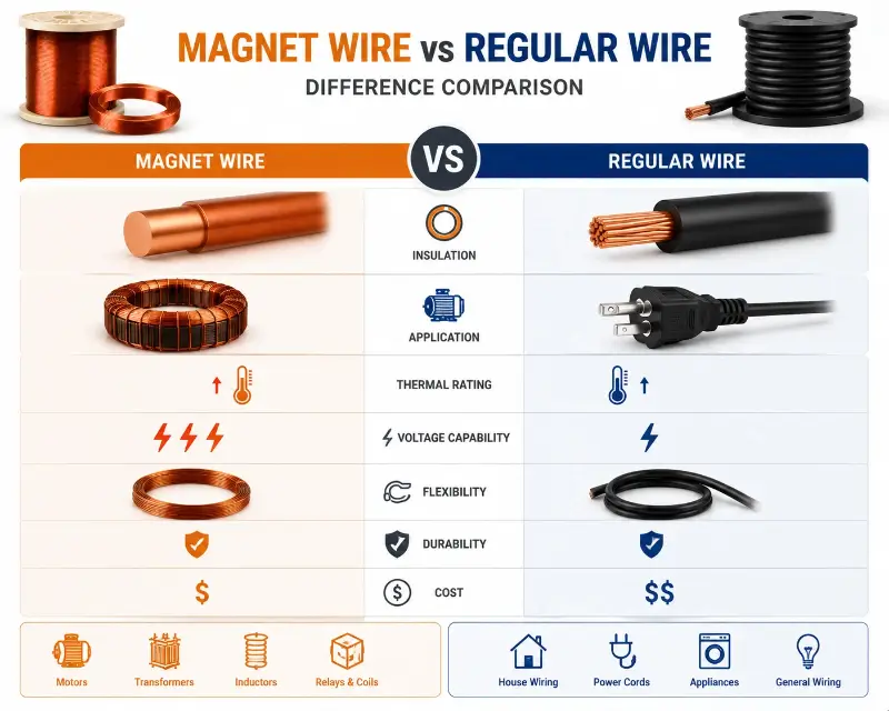
The core difference between high frequency magnet wire and power frequency magnet wire is reflected in the ability to suppress skin effect and proximity effect. Power frequency magnet wire (50/60 Hz) only needs to consider DC resistance and insulation strength, with cross-section utilization reaching 100%; while high frequency magnet wire in the 1 MHz and above band, single-strand round wire with the same cross-section can have AC losses 10–50 times the DC losses, requiring multi-strand refinement, precise stranding, and double insulation processes to achieve low-loss transmission. This engineering trade-off determines that high frequency magnet wire must be produced by professional specialty winding wire manufacturers, with process barriers in fine diameter control (Φ0.04 mm grade), precise stranding (pitch tolerance ±5%), and low-defect enamel film (pinhole count ≤ 5/30 m). This is also the fundamental reason why high frequency magnet wire prices are typically 3–10 times that of power frequency magnet wire.
The core quality indicators of high frequency magnet wire are ACF (AC resistance factor), enamel film integrity, and insulation reliability. ACF reflects the effective conductivity under high frequency, enamel film integrity determines inter-turn insulation reliability, and insulation reliability directly relates to the partial discharge life under high frequency square waves. The Type 1–6 classification of ASTM B-286 and the IEC 60317 series standards provide complete engineering specifications for high frequency magnet wire, while application standards such as AEC-Q200 and UL 94 V-0 are oriented toward special scenarios such as automotive and flame retardant. In specific applications, comprehensive selection must combine working frequency band, working temperature, Q value requirements, insulation grade, and cost budget, prioritizing suppliers with IEC 60317 + ASTM B-286 + application standard (such as AEC-Q200) triple certification system. Precise stranding process, enamel film sintering temperature matching (to avoid secondary annealing causing magnet wire performance degradation), and ACF measured data are the three core dimensions for evaluating the technical capability of high frequency magnet wire suppliers.