


Introduction
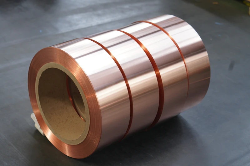
In the context of new-energy-vehicle (NEV) electric drive systems, copper foil refers to high-purity rolled or electrolytic flat copper strip with a typical thickness ranging from 0.01 mm to 0.5 mm and an aspect ratio (width-to-thickness ratio) exceeding 100:1. It serves as one of the most fundamental conductor materials across the vehicle’s power electronics and electromagnetic circuitry—spanning battery packs and DC busbars, stator windings of traction motors, inverter busbars and IGBT substrates, high-frequency transformer windings, and on-board chargers. As NEV platforms evolve toward 800 V high-voltage architectures, silicon carbide (SiC) MOSFET inverters, hairpin-type flat-wire motor windings, and cell-to-pack (CTP)/cell-to-chassis (CTC) battery configurations, the operational temperature, current density, switching frequency, and vibration loads imposed on copper foil have significantly increased compared to conventional 400 V silicon-based IGBT drive systems and cylindrical-cell battery packs. Conventional multi-strand copper cables and round enameled wires can no longer simultaneously satisfy the composite requirements of high current density, low parasitic impedance, efficient thermal dissipation, and mass-producible weldability. High-purity copper foil—characterized by its excellent electrical conductivity (≥100 % IACS), superior thermal conductivity (≥390 W/m·K), high flexibility, and compatibility with automated laser welding and ultrasonic welding—has become an indispensable foundational material in NEV electric drive engineering. A systematic understanding of “Copper Foil for NEV Electric Drive” requires examination across five dimensions: material system, key performance indicators, application scenarios within electric drive assemblies, manufacturing processes, and automotive-grade reliability validation frameworks. This article proceeds sequentially through “material fundamentals—performance specifications—three major application families—manufacturing processes—validation testing,” providing a comprehensive technical reference for powertrain design engineers and copper foil suppliers in the NEV sector.
Material System for NEV-Grade Copper Foil
Chemical Composition and Electrical Conductivity Grade
NEV-grade copper foil is almost exclusively manufactured from oxygen-free high-conductivity (OFHC) copper, with typical grades including C11000 (electrolytic tough pitch copper, ETP; Cu ≥ 99.95 %, O = 0.02–0.04 %), C10200 (oxygen-free copper; Cu ≥ 99.95 %, O < 0.001 %), and C10100 (extra-high-purity oxygen-free copper; Cu ≥ 99.99 %) for the most stringent high-frequency performance requirements. The chemical purity of the copper foil directly determines its electrical and thermal conductivity: trace impurities such as phosphorus, iron, sulfur, and antimony drastically reduce both electrical conductivity and thermal diffusivity. In the annealed (O temper) condition, C11000 typically achieves an electrical conductivity of 100–101 % IACS (International Annealed Copper Standard), whereas C10200 and C10100—owing to their near-zero oxygen content—achieve conductivities of 101–102 % IACS. Phosphorus-deoxidized copper (C12200, DHP) is occasionally employed where superior brazing performance is required; however, its electrical conductivity drops to approximately 85 % IACS, limiting its use to thermal management and brazed busbar applications—not primary current-carrying paths.
Surface Treatment and Plating Structure
Bare copper foil rapidly forms a cuprous oxide (Cu₂O) layer upon exposure to ambient air at room temperature, resulting in increased contact resistance and reduced solderability. NEV-grade copper foil therefore relies on multiple surface treatment options: electroplated tin (Sn, thickness 1–5 µm) ensures solderability and oxidation resistance; electroplated silver (Ag, thickness 1–3 µm) is used in high-temperature and high-frequency applications (silver plating retains conductivity up to 200 °C and delivers superior skin-effect performance above 100 kHz); electroplated nickel (Ni, thickness 1–3 µm) serves as a diffusion barrier and corrosion-resistant layer—particularly critical for battery tab applications under high-temperature, high-humidity conditions. For busbar and battery tab applications, organic solderability preservative (OSP) coating—also termed anti-tarnish coating—provides temporary oxidation protection during storage and reflow soldering, and decomposes spontaneously during the soldering process.
Mechanical and Thermal Performance Profile
The mechanical and thermal properties of copper foil are jointly determined by temper condition, grain structure, and trace impurity content. Four standard temper conditions are commonly employed: annealed (O temper, soft temper, elongation after fracture ≥ 30 %), one-quarter hard (1/4H, H01), one-half hard (1/2H, H02, elongation after fracture 10–20 %), and full-hard (H, H04, tensile strength 350–450 MPa). NEV motor busbar applications predominantly specify 1/4H or 1/2H tempers to balance formability during bending and stamping operations with requisite mechanical strength. The coefficient of thermal expansion (CTE) of pure copper is 16.5×10⁻⁶ /K; matching this value to that of silicon (2.6×10⁻⁶ /K) requires incorporation of a flexible intermediate layer; in battery pack applications, CTE mismatch between copper and aluminum housings (~23×10⁻⁶ /K) is compensated via ultrasonic welding process parameters and nickel diffusion barrier layers.
Key Performance Indicator System
Conductivity and Skin Effect
Conductivity is the most fundamental property of NEV copper foil. Under DC conditions, conductivity is determined by the IACS grade and temper condition. Under high-frequency AC conditions (e.g., inverter switching transients at 10–100 kHz and SiC switching frequencies up to 500 kHz), the skin effect confines current flow to a thin surface layer of thickness δ = √(2ρ/(ωμ)), where ρ is resistivity, ω is angular frequency, and μ is magnetic permeability. At 100 kHz, the skin depth δ for pure copper is ≈ 0.21 mm; at 500 kHz, δ ≈ 0.094 mm. Therefore, NEV copper foil for high-frequency busbar and planar transformer applications is typically specified with thicknesses between 0.1 mm and 0.3 mm—sufficient to carry the full DC current while avoiding ineffective conductor volume beneath the skin layer. Silver-plated copper foil further reduces AC resistance by leveraging silver’s superior high-frequency conductivity.
Thermal Conductivity and Heat Dissipation Performance
Annealed (O-temper) C11000 copper foil exhibits thermal conductivity up to 391 W/(m·K), significantly higher than aluminum (~205 W/(m·K)) and far exceeding any polymer or composite material. In NEV applications, copper foil serves both as current-carrying conductor and as a heat-spreading element. In hairpin stator windings of NEV traction motors, copper foil forms the primary thermal conduction path from the slot interior to the end-winding region, complementing the cooling function of the housing-integrated water/oil cooling jacket. In IGBT/SiC inverter power modules, direct-bonded copper (DBC) ceramic substrates utilize copper foil bonded to alumina (Al₂O₃) or aluminum nitride (AlN) to spread heat from the die to the cold plate. However, copper’s relatively high coefficient of thermal expansion (CTE) necessitates sufficient bond flexibility in DBC structures to accommodate CTE mismatch during temperature cycling from −40 °C to 150 °C.
Mechanical Strength and Formability
The mechanical strength of NEV copper foil is characterized by three core parameters: tensile strength, elongation after fracture, and bending fatigue life. Annealed C11000 foil (0.2 mm thick) exhibits tensile strength ≈ 220 MPa and elongation after fracture ≥ 30 %; 1/2H temper increases tensile strength to 250–300 MPa while reducing elongation after fracture to 10–20 %. In battery tab applications, copper foil must withstand ≥ 5 cycles of 180° bending without cracking to ensure long-term reliability under vibration loads transmitted between the battery pack and vehicle chassis. In motor busbar applications, copper foil must endure continuous stamping, bending, and torsion without cracking or excessive work hardening—particularly critical for hairpin windings, where the copper strip transitions from rectangular cross-section within the slot to circular cross-section at the weld joint.
Weldability and Process Compatibility
Welding processes employed for NEV copper foil include laser welding (fiber laser or blue laser, spot or seam welding), ultrasonic welding (20–40 kHz, pressure 1–5 kN), resistance welding (spot welding, projection welding), and reflow soldering. Each process imposes specific requirements on foil surface condition, thickness uniformity, and hardness. Laser welding demands a smooth, oxide-free surface (typically tin- or silver-plated) with thickness tolerance ≤ ±5 %; ultrasonic welding requires a micro-rough surface (Ra 1.0–2.5 µm) to ensure stable frictional coupling; reflow soldering requires OSP coating or tin plating with controlled intermetallic compound (IMC) growth. On modern hairpin motor production lines, dual-pulse fiber laser welding has become the mainstream technology, owing to its high speed (> 50 mm/s), narrow heat-affected zone, and excellent repeatability.
Application I — Stator Windings and Busbars for NEV Traction Motors
Hairpin Windings and Flat Copper Foil Busbars
NEV traction motors rated at 150–400 kW commonly employ hairpin winding technology, replacing conventional round magnet wire with rectangular flat copper conductors—often referred to as flat copper wire or copper strip. Each hairpin consists of a U-shaped segment of flat copper strip inserted into stator slots; the ends are then welded to form a continuous wave winding. The flat copper strip used for hairpin windings is essentially thick copper foil (thickness: 1.0–3.0 mm; width: 4.0–8.0 mm), supplied in continuous coil form and processed via continuous stamping and bending, with insulation provided by paper or polyimide film. Compared to round-wire windings, copper foil hairpin windings offer three key advantages: (1) higher slot fill factor (70–80 % vs. 45–55 % for round wire), increasing torque density by 15–20 %; (2) superior thermal conduction along the copper strip, reducing hotspot temperature by 10–15 K; and (3) compatibility with automated hairpin insertion and laser welding, enabling cycle times per stator below 90 seconds.
Inverter-to-Motor Busbars and High-Voltage DC Power Distribution
High-voltage DC busbars interconnecting the battery pack, inverter DC-link capacitors, and motor terminals are fabricated from laminated copper foil or extruded copper bar. On 800 V platforms with peak currents exceeding 600 A, laminated copper foil busbars—comprising multiple insulated copper foil layers (each 0.2–0.5 mm thick), bonded with epoxy or polyimide film—offer superior high-frequency current distribution, lower stray inductance (typically < 10 nH), and enhanced thermal dissipation compared to solid copper bars. Copper foil for laminated busbars is typically C11000 1/2H temper, with tin plating applied to prevent corrosion and ensure compatibility with laser welding.
Current Sensing and Rogowski Coil Integration
Precise current sensing is critical for NEV motor control. Rogowski-coil-based current sensors are increasingly deployed in 800 V inverter systems, leveraging copper foil printed circuit integration to achieve high bandwidth (DC to > 1 MHz), low insertion loss, and immunity to DC saturation. In such applications, copper foil thickness is typically 0.1–0.3 mm; coil patterns are etched onto flexible polyimide substrates, with surface finish applied via ENIG (electroless nickel immersion gold) to ensure solderability and corrosion resistance. The combination of high electrical conductivity, fine-feature etching capability, and compatibility with flexible substrates makes copper foil a uniquely suitable material for integrated Rogowski coil current sensing applications.
Application II — Cell-to-Pack and Tab Connections in Battery Packs
Tab Materials for Cylindrical and Pouch Cells
NEV battery packs based on 18650, 21700, or 4680 cylindrical cells—or large-format pouch cells—employ copper foil as the negative current collector. Within each cell, the negative current collector consists of electrolytic tough-pitch (ETP) copper foil, 6–12 µm thick, coated with graphite-based anode material. In cylindrical cells, bare copper foil serves directly as the cell tab. In the 4680 cell, the full-tab design—where copper foil extends along the entire winding length—replaces the conventional small-tab configuration, significantly reducing internal resistance and enabling continuous discharge rates of 5C–10C. The ETP copper foil used in 4680 cells must meet extremely stringent requirements: tensile strength ≥ 400 MPa, elongation after fracture ≥ 5 %, surface roughness Ra ≤ 2.0 µm, and thickness tolerance ±3 %.
Cell-to-Busbar Connection and Ultrasonic Welding
External cell-to-busbar connections are established via ultrasonic welding of copper foil (or copper strip) to the cell tab. Tin-plated copper foil tabs, 0.2–0.4 mm thick, are widely adopted in cylindrical-cell battery packs; on the positive side, aluminum tabs, 0.2–0.3 mm thick, are used due to compatibility with the cathode chemistry. The process window for ultrasonic welding is narrow: weld strength must exceed 30 N per 10 mm weld length, while avoiding overheating that could compromise cell sealing or trigger thermal runaway. To comply with automotive standards AEC-Q100/Q200 and GB 38031, copper foil connections in battery packs must pass rigorous vibration testing (10–2000 Hz, 30 m/s², ≥ 100 h), mechanical shock testing (50 g, 11 ms half-sine waveform), and temperature cycling (−40 °C to +85 °C, ≥ 1000 cycles).
Pack-Level Architectures: CTP and CTC
Cell-to-Pack (CTP) and Cell-to-Chassis (CTC) architectures—pioneered by BYD (Blade Battery), Contemporary Amperex Technology Co. Limited (CATL) (Qilin Battery), and Tesla (Structural Battery)—eliminate module housings and integrate busbars into pack-level structural components, substantially reducing copper foil and busbar usage at the pack level. Within CTP/CTC packs, inter-cell connections typically employ copper foil strips bonded/welded via structural adhesive, friction stir welding, or laser welding—simultaneously fulfilling both electrical and structural functions. Copper foil for CTP/CTC applications must satisfy demanding fatigue life requirements (typically ≥ 10 million cycles at ±0.1 % strain amplitude), owing to the direct coupling of electrical and mechanical functionality.
Application III — Power Electronics, Planar Transformers, and On-Board Chargers (OBCs)
IGBT/SiC Inverter Substrates and Direct Bonded Copper (DBC)
In NEV traction inverters built with Insulated Gate Bipolar Transistor (IGBT) or Silicon Carbide (SiC) MOSFET power modules, Direct Bonded Copper (DBC) substrates serve as the primary electrical and thermal interface. A DBC substrate consists of a ceramic dielectric layer—alumina (Al₂O₃, 0.38–0.63 mm), aluminum nitride (AlN, 0.63–1.0 mm), or silicon nitride (Si₃N₄, 0.32 mm)—sandwiched between two copper foil layers (typically 0.2–0.6 mm thick). The top copper layer is etched into circuit traces to carry current from power dies; the bottom copper layer functions as a continuous heat-spreading layer bonded to the cold plate. For 800 V SiC inverter modules, Si₃N₄ ceramic paired with C10200 high-purity oxygen-free copper foil is commonly specified, leveraging its exceptional thermal cycling reliability (>50,000 cycles between −40 °C and 250 °C) and high thermal conductivity.
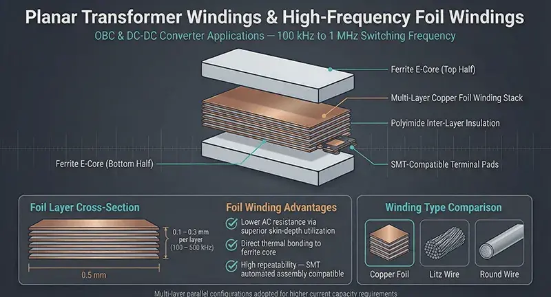
Planar Transformer Windings and High-Frequency Foil Windings
On-board chargers (OBCs) and DC-DC converters operating at switching frequencies from 100 kHz to 1 MHz employ planar transformers and inductors wound with copper foil. Compared to litz wire or round-wire windings, copper foil windings offer: (1) superior skin-depth utilization and lower AC resistance at high frequencies; (2) improved thermal coupling between winding and core (copper foil can be directly bonded to ferrite cores); and (3) enhanced repeatability in SMT-style automated assembly. Copper foil thickness for planar transformer windings is selected based on skin depth at the operating frequency—typically 0.1–0.3 mm for 100–500 kHz, with multi-layer parallel configurations adopted when higher current capacity is required.
Wireless Charging Coil Foil and Electromagnetic Shielding
NEV wireless charging systems (typically 7–22 kW ground-to-vehicle) utilize copper foil litz coils or copper foil spiral coils operating at 85 kHz. Such coils are fabricated from wide-format copper foil strip (0.2–0.3 mm thick), insulated externally with polyimide film or polyester felt, then etched or cut into spiral patterns. Beyond their primary coil function, copper foil also provides electromagnetic interference (EMI) shielding within OBC, DC-DC, and wireless charging enclosures—commonly implemented as laminated copper foil (0.05–0.1 mm thick) bonded to polymer films.
NEV Copper Foil Manufacturing Processes
Rolled Annealed (RA) vs. Electrodeposited (ED) Process Routes
NEV copper foil is manufactured via two distinct process routes: Rolled Annealed (RA) and Electrodeposited (ED). The RA route begins with continuous casting of thick copper strip (typically 10–20 mm), followed by hot rolling, cold rolling, and annealing to progressively reduce thickness to the final foil gauge (0.01–0.5 mm). RA copper foil exhibits superior ductility, elongation after fracture (O-temper ≥ 30 %), and mechanical isotropy—properties rendering it the preferred choice for hairpin windings, busbars, and structural pack applications. The ED route dissolves copper anodes in a copper sulfate electrolyte, enabling copper ion deposition onto a rotating titanium drum cathode; the deposited copper is subsequently stripped, cleaned, and surface-treated to produce ultra-thin ED copper foil (6–35 µm). ED copper foil is primarily used as the anode current collector within lithium-ion batteries; its single- or double-sided surface roughness (Ra 0.5–3.5 µm) is critical for adhesion of graphite anode coatings.
Surface Treatment & Anti-Oxidation Coating Lines
NEV copper foil surface treatment lines typically comprise degreasing, micro-etching (sulfuric acid–hydrogen peroxide acid cleaning), anti-oxidation coating (OSP, benzotriazole derivatives, or imidazole derivatives), and electroplating with tin/silver/nickel. OSP coating thickness is typically 0.1–0.3 µm, providing shelf-life protection for 6–12 months. Tin plating thickness for busbar and battery tab applications ranges from 1–5 µm, often followed by a reflow step to form a Cu–Sn intermetallic compound (IMC) layer. For high-frequency applications, silver plating thickness is 1–3 µm of pure silver, optionally supplemented with an anti-oxidation topcoat.
Slitting, Stamping, and Laminating Processes
Finished copper foil is processed into application-specific configurations: slit into narrow strips (for busbar and hairpin winding applications), continuously stamped into complex geometries (e.g., Rogowski coils and planar transformer windings), or laminated with dielectric films (polyimide PI, polyethylene terephthalate PET, or epoxy prepreg) to form laminated busbars. Slitting tolerance is critical for motor busbar applications (width tolerance ≤ ±0.05 mm), while laminated bond strength must exceed 5 N/cm peel strength to withstand thermal cycling and vibration.
Quality Testing and Automotive-Grade Qualification
Electrical, Mechanical, and Thermal Test Standards
NEV copper foil qualification employs a comprehensive test matrix. Electrical tests include DC resistivity (per ASTM B193 or IEC 60028), AC impedance and skin-effect resistance (per IPC TM-650 2.5.5), and dielectric withstand voltage of the insulation layer (per ASTM D149). Mechanical tests include tensile strength and elongation at break (per ASTM E8), bending fatigue (per ASTM E796), and hardness (per ASTM E384). Thermal tests include thermal conductivity (per ASTM E1461, laser flash method), coefficient of thermal expansion (CTE) (per ASTM E228), and temperature cycling durability (per IPC-9701). Surface tests include surface roughness (per ISO 4287), coating thickness (X-ray fluorescence method per ASTM B568), and solderability (per IPC J-STD-002).
IATF 16949 and AEC-Q100/Q200 Qualification
The automotive-grade qualification system for NEV copper foil rests on three pillars: (1) IATF 16949 quality management system certification of the manufacturing facility; (2) submission of PPAP (Production Part Approval Process) per AIAG standards, including Design FMEA, Process FMEA, Control Plan, and MSA studies; and (3) stress-test qualification per AEC-Q100 (for active components) and AEC-Q200 (for passive components), including High-Temperature Operating Life (HTOL, 1000 hours at 125 °C), Temperature-Humidity Bias (THB, 1000 hours at 85 °C / 85 % RH), and Thermal Shock testing (−55 °C to +150 °C, 1000 cycles). Tier-1 NEV suppliers—including Bosch, ZF, BYD, and CATL—require all copper foil and busbar materials to pass these qualification thresholds prior to volume production.
Environmental Compliance and Recyclability
Environmental compliance for NEV copper foil encompasses EU RoHS 2.0 (restricting lead, cadmium, mercury, hexavalent chromium, polybrominated biphenyls, polybrominated diphenyl ethers, DEHP, BBP, DBP, and DIBP), EU REACH (restricting SVHC substances), and China’s GB/T 26572 standard. Beyond regulatory compliance, copper foil is inherently recyclable: copper recovery rates from end-of-life EV battery packs and motors exceed 95 %, supporting the NEV industry’s circular economy objectives through smelting and refining. Recycled copper (e.g., C11000 RCu or C11000 RCu + Zn grades) may be used in non-critical busbar applications without performance loss, provided trace impurity levels—particularly phosphorus and iron—are tightly controlled.
Conclusion
Copper foil selection for electric drive applications in new energy vehicles (NEVs) is a multidimensional engineering decision, encompassing material purity (C11000, C10200, C10100, or C12200), surface finish (bare copper, OSP, tin-plated, silver-plated, or nickel-plated), temper condition (O, 1/4H, 1/2H, or H), thickness (0.01–3.0 mm), and application-specific forms (strip, foil, copper strip, hairpin strip, or DBC laminates). Spanning three major application families—traction motor stators and busbars (hairpin windings, laminated DC busbars, Rogowski coil current sensing), battery packs (cell tabs, 4680 full-tab designs, ultrasonically welded busbars, CTP/CTC structural packs), and power electronics (IGBT/SiC inverter DBC substrates, planar transformer windings, wireless charging coils, EMI shielding)—copper foil must simultaneously deliver high electrical conductivity (≥ 100 % IACS), high thermal conductivity (≥ 390 W/m·K), mechanical robustness against vibration and thermal cycling, solderability suitable for automated high-volume production, and compliance with automotive-grade reliability standards (IATF 16949, AEC-Q100/Q200). As NEV platforms continue evolving toward 800 V/1000 V architectures, SiC-based inverters, hairpin-type flat-wire motor windings, and CTP/CTC-structured battery packs, demand for high-purity, high-reliability, and highly engineered copper foil will persistently expand. Future directions may include: thinner, higher-strength electrodeposited (ED) copper foil for solid-state battery anodes; silver-plated copper foil for planar transformer applications above 1 MHz; and copper foil structural busbar composites integrating both electrical conduction and mechanical load-bearing functions within CTP/CTC pack architectures—collectively reinforcing copper foil’s foundational role as a core material in next-generation NEV electric drive systems.