


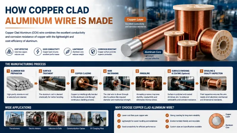
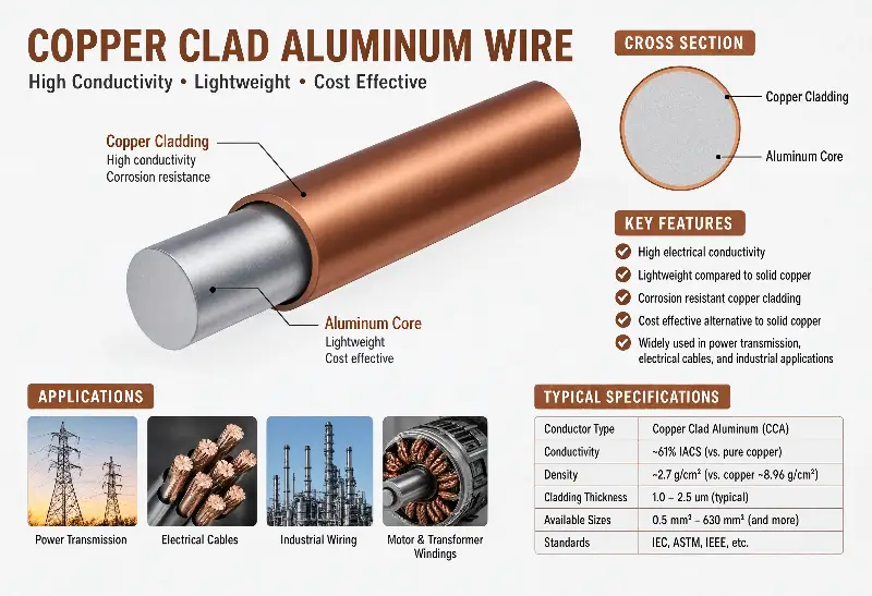
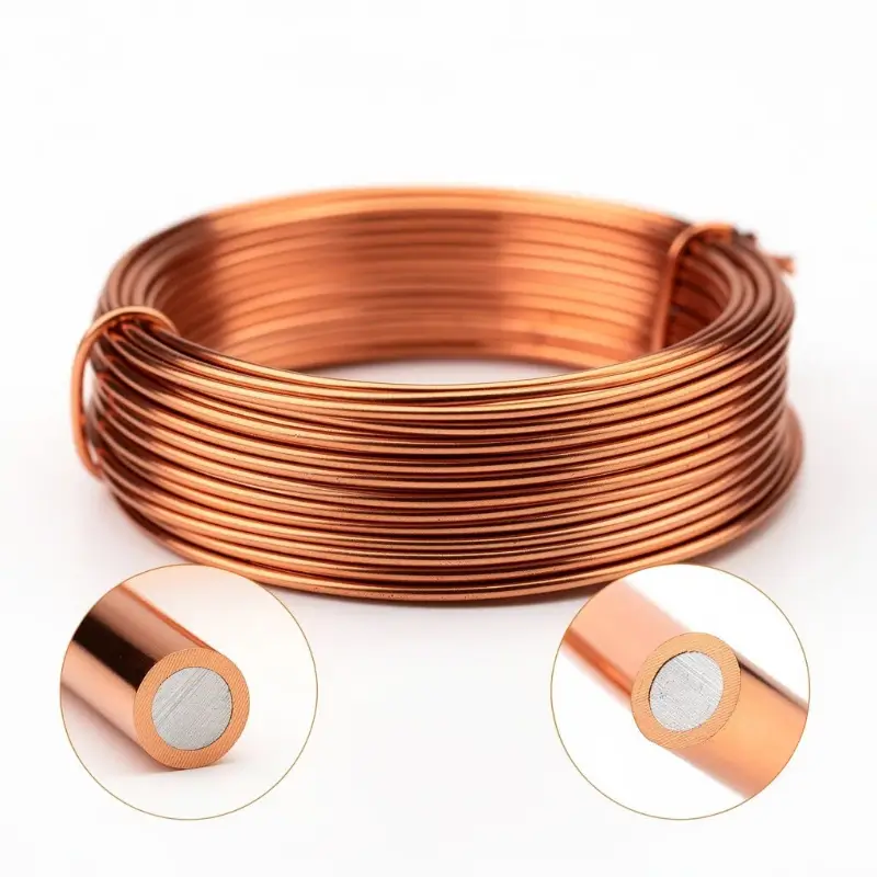
Copper clad aluminum wire (CCA) is a bimetallic composite conductor in which a layer of oxygen-free copper is continuously clad around an aluminum core using a metallurgical bonding process. Its defining feature is that the copper layer occupies 10% or 15% of the conductor cross-sectional area, classified under ASTM B-566 as Class 10A, 15A, 10H, and 15H. The aluminum core uses electrical conductor-grade aluminum, producing a concentric structure of copper on the outside and aluminum on the inside. This structure gives CCA the solderability and oxidation resistance of copper combined with the low density and low cost of aluminum, making it an engineering solution for replacing pure copper wire.
In weight-sensitive electrical applications, CCA is approximately 60%–70% lighter than pure copper wire (copper density 8.96 g/cm³, aluminum density 2.70 g/cm³). Its DC conductivity is approximately 65% of pure copper for Class 15A (15% copper volume) and 63% for Class 10A (10% copper volume). In high-frequency applications above 5 MHz, the skin effect concentrates current in the copper layer, so the AC conductivity of CCA approaches that of pure copper.
This article systematically explains the manufacturing process and engineering applications of CCA from six perspectives: material composition, process principles, production flow, standard system, performance comparison, and quality control.
Copper Clad Aluminum Wire Overview and Industry Positioning
Definition and Material Composition
Copper clad aluminum wire is a bimetallic composite conductor composed of a concentric aluminum core and a continuous copper cladding layer:
- Aluminum Core: Electrical-grade aluminum (1350-O or similar grade), purity ≥ 99.5%
- Copper Layer: Oxygen-free copper (OFC, C10100 or C10200), purity ≥ 99.95%
- Copper Layer Volume Ratio: 10% (Class 10A/10H) or 15% (Class 15A/15H)
- Bonding Method: Metallurgical bonding that forms an intermetallic compound transition layer at the cladding interface
The aluminum core and copper layer form a continuous metallic bond at the cladding interface through atomic diffusion, preventing delamination and peeling. This is the core feature that distinguishes CCA from copper-plated aluminum wire. The latter only forms a mechanical bond through electroplating, which gives low bond strength and easy delamination.
Engineering Reasons for the Existence of CCA
| Dimension | Pure Copper Wire | Pure Aluminum Wire | Copper Clad Aluminum Wire (CCA) |
|---|---|---|---|
| Density (g/cm³) | 8.96 | 2.70 | 3.63–4.10 (depending on copper volume ratio) |
| DC Resistance (relative to copper) | 1.00 | 1.61 (equal cross-section) | 1.55–1.59 (Class 10A) |
| Weight (same cross-section, same length) | 1.00 | 0.30 | 0.40–0.46 |
| Solderability | Excellent | Poor (requires special flux) | Excellent (outer copper layer) |
| Oxidation Resistance | Good | Poor (forms alumina) | Good (outer copper layer) |
| Cost (relative to copper) | 1.00 | 0.30 | 0.55–0.65 |
| High-Frequency Conductivity (> 5 MHz) | Excellent | Medium | Excellent (skin effect) |
The core value of CCA lies in its bimetallic structure, which simultaneously delivers the surface engineering properties of copper and the low density, low cost advantages of aluminum. This structure gives CCA unique engineering value in weight-sensitive wires and cables, enameled wire, and RF coils.
CCA Industry Chain Positioning
Copper clad aluminum wire belongs to the composite conductor sub-category under the major category of electrical materials. Its main applications include:
- Enameled wire: Φ0.19–4.0 mm enameled CCA (ECCAW) for transformers, motors, and induction coils
- Power cables: high-frequency power transmission and lightweight wiring
- Building wiring: residential wiring (replacing part of pure copper wire)
- Automotive wiring harnesses: driven by lightweight requirements
- Wireless charging and RFID: high-frequency applications replacing pure copper wire
Global annual CCA production is approximately 500,000–700,000 tons, accounting for 5%–8% of total electrical conductor production. China is the world’s largest CCA producer, accounting for over 60% of global capacity.
Raw Material Selection and Preparation
Aluminum Core Material Requirements
The aluminum core is the core material of CCA and must meet strict chemical composition and metallurgical quality requirements:
- Aluminum Purity: ≥ 99.5% (electrical-grade 1350 series) or ≥ 99.7% (high-purity aluminum)
- Impurity Control: Iron (Fe) ≤ 0.25%, Silicon (Si) ≤ 0.10%, Copper (Cu) ≤ 0.05%
- Oxygen Content: ≤ 0.01% (to avoid alumina inclusions)
- Hydrogen Content: ≤ 0.10 ml/100g Al (to avoid pinhole defects)
- Initial State: Annealed (O state) or half-hard (H14)
The common diameter range of aluminum cores is Φ8.0–16.0 mm, depending on the diameter and compression ratio of the target CCA product. The surface of the aluminum core must be cleaned and polished to remove oxide film and oil stains, ensuring the metallurgical bonding quality of the cladding interface.
Oxygen-Free Copper Cladding Material
The copper layer uses oxygen-free copper (C10100 or C10200), with the following core requirements:
- Copper Purity: ≥ 99.95% (C10100 requires ≥ 99.99%)
- Oxygen Content: ≤ 0.0005% (C10100) or ≤ 0.001% (C10200)
- Impurity Control: Phosphorus (≤ 0.0003%), Sulfur (≤ 0.0015%), and total trace elements ≤ 0.025%
- Initial State: Annealed (O state) for subsequent drawing and cladding
The initial form of oxygen-free copper is typically a round tube or flat strip. Common specifications:
- Round tube outer diameter: Φ10–20 mm
- Round tube wall thickness: 1.0–3.0 mm (depending on the target copper volume ratio)
- Round tube length: customized for the CCA production line (typically 1000–3000 m per coil)
The concentricity and wall thickness uniformity of copper tubes directly affect the accuracy of copper volume ratio and concentricity of the finished CCA, making raw material inspection a key link in quality control.
Copper-Aluminum Volume Ratio (10A/15A/10H/15H)
According to ASTM B-566, CCA is classified into four categories based on copper layer volume ratio and final state:
| Category | Copper Volume Ratio | Final State | Typical Application |
|---|---|---|---|
| Class 10A | 10% | Annealed | High-flexibility applications (enameled wire, coils) |
| Class 15A | 15% | Annealed | High-conductivity requirements (cable core) |
| Class 10H | 10% | Hard-drawn | Structural strength requirements (overhead lines) |
| Class 15H | 15% | Hard-drawn | Strength and conductivity balance (specialty cables) |
Copper volume ratio is not a weight ratio. Taking Φ1.0 mm CCA as an example:
- Class 10A: Aluminum core Φ0.92 mm + copper layer thickness 0.04 mm (double-layer thickness)
- Class 15A: Aluminum core Φ0.89 mm + copper layer thickness 0.055 mm (double-layer thickness)
Increasing the copper volume ratio from 10% to 15% reduces DC resistance by approximately 3%–5% but increases cost by 8%–12%. Engineering experience: when the copper volume ratio exceeds 20%, the cost advantage of CCA disappears and pure copper wire should be used directly.
Cladding Process Principles
Continuous Cladding and Metallurgical Bonding
The core process of CCA is continuous cladding. The procedure is as follows:
- Pre-cleaning: The aluminum core and copper tube are chemically cleaned or mechanically polished to remove surface oxide films and oil stains.
- Pre-forming: The copper tube is reduced in diameter using a sizing mill to closely fit the aluminum core.
- Heating: Heated to 400–600°C (below the recrystallization temperature of copper) under inert gas protection.
- Extrusion Bonding: The copper-aluminum interface undergoes atomic diffusion through extrusion under high temperature and pressure.
- Metallurgical Bonding: A Cu-Al intermetallic compound (CuAl₂, Cu₉Al₄, etc.) transition layer forms at the interface.
- Cooling: Slow cooling under a protective atmosphere avoids interface stress.
The strength of the metallurgical bond depends on:
- Temperature: The interface temperature must reach above 350°C to promote atomic diffusion
- Pressure: Extrusion pressure ≥ 50 MPa
- Time: High-temperature holding time ≥ 0.5 s
- Atmosphere: Oxygen content ≤ 50 ppm to prevent oxidation
The interface bond strength directly affects subsequent drawing processes and finished product performance. Poor bonding can cause fatal defects such as delamination and blistering.
Surface Pretreatment Before Cladding
The aluminum core and copper tube must be thoroughly cleaned of surface contaminants before cladding. Pretreatment processes include:
- Chemical Cleaning: NaOH solution (5–10%) removes the aluminum oxide film, followed by HNO₃ neutralization and water rinsing
- Mechanical Polishing: Wire brush and abrasive belt polishing remove macroscopic defects
- Ultrasonic Cleaning: Removes micron-sized particles and oil stains
- Drying: Hot air drying or vacuum drying, surface water content ≤ 0.1 mg/m²
- Inert Gas Protection: Immediately after cleaning, a protective atmosphere (nitrogen or argon) is introduced
The surface roughness (Ra) of the aluminum core and copper tube after pretreatment should be controlled between 0.8–1.6 μm. Excessive roughness leads to uneven bonding, while excessive smoothness reduces mechanical locking.
Process Atmosphere and Temperature Control
The cladding process must be carried out under a protective atmosphere to avoid secondary oxidation of aluminum and copper:
- Atmosphere Selection: Nitrogen (99.99% purity) or argon (99.999% purity)
- Oxygen Content Control: Oxygen content in the cladding zone ≤ 50 ppm
- Temperature Profile: Preheating zone 200°C → cladding zone 400–600°C → holding zone 300–400°C → slow-cooling zone below 200°C
- Temperature Uniformity: Within ±10°C, avoiding local overheating or cooling
Some high-end production lines use vacuum induction heating or laser local heating, which achieve more precise temperature control, but the equipment cost is significantly higher than traditional gas protective furnaces.
Core Manufacturing Processes
Drawing and Cladding Production Line Configuration
A typical CCA production line is configured as follows:
Aluminum core payoff → Chemical cleaning → Mechanical polishing → Ultrasonic cleaning → Drying
↓
Copper tube payoff → Cleaning → Sizing →
↓
Assembly and centering → Induction heating → Extrusion cladding → Slow cooling
↓
Rough drawing (multiple passes) → Intermediate annealing → Fine drawing → Final annealing
↓
Online inspection (diameter, eccentricity, resistance) → Take-up
Key equipment in a typical CCA production line:
- Aluminum core payoff stand: Tension control ±5%
- Copper tube payoff stand: Dual-disc alternation, ensuring continuous production
- Sizing machine: 2–4 passes for precise copper tube diameter reduction
- Induction heating furnace: High-frequency induction (100–500 kHz), power 50–200 kW
- Extrusion dies: Carbide or polycrystalline diamond (PCD), die life 100–500 km
- Drawing machine: Sliding-type or multi-die continuous, drawing speed 200–1000 m/min
- Online annealing furnace: Resistance annealing or induction annealing
- Online inspection: Laser diameter measurement, eddy current testing, resistance measurement
Production line length is typically 60–120 m, with annual capacity of 1000–5000 tons.
Annealing Process and Mechanical Properties
Annealing is a key process in CCA manufacturing, determining the final mechanical properties:
- Intermediate Annealing (between drawing passes): Eliminates work hardening and restores plasticity
- Annealing temperature: 350–450°C
- Holding time: 1–4 h
- Protective atmosphere: nitrogen or argon
- Final Annealing (final state control):
- Class 10A/15A: Annealing at 450–550°C, elongation ≥ 25%
- Class 10H/15H: No annealing required, retaining work-hardened state, tensile strength ≥ 200 MPa
Effect of annealing temperature on elongation (taking Φ1.0 mm CCA as an example):
| Annealing Temperature (°C) | Tensile Strength (MPa) | Elongation (%) | Applicable Category |
|---|---|---|---|
| No Annealing (Hard State) | 200–250 | 1–3 | Class 10H/15H |
| 300 | 150–180 | 8–12 | — |
| 400 | 120–150 | 15–20 | — |
| 500 | 90–120 | 25–35 | Class 10A/15A |
Insufficient annealing leads to substandard elongation (affecting subsequent winding), while excessive annealing reduces tensile strength (affecting structural applications).
Real-Time Process Parameter Control
CCA production requires real-time monitoring of the following key parameters:
- Drawing speed: 200–1000 m/min (depending on wire diameter and compression ratio)
- Compression ratio per pass: ≤ 25% (to prevent interface separation)
- Total compression ratio: From aluminum core to finished product, Φ8.0 mm → Φ1.0 mm, total compression ratio approximately 64:1
- Annealing tension: 5–20 N (for wire diameter Φ0.5–2.0 mm)
- Take-up tension: ±5% accuracy
- Cooling water flow rate: Ensures wire temperature ≤ 80°C after drawing
Modern CCA production lines widely use SCADA systems and SPC (Statistical Process Control) to monitor and feed back more than 30 process parameters in real time.
Post-Cladding Treatment
Surface Cleaning and Quality Control
After cladding, CCA wire requires surface treatment:
- Acid Pickling: Dilute sulfuric acid (5–10%) or dilute hydrochloric acid to remove oxide scale
- Neutralization: NaOH solution to neutralize residual acid
- Water Rinse: Deionized water rinse until resistivity ≥ 1 MΩ·cm
- Lubricant Coating: Drawing lubricant (soap-based or synthetic)
- Drying: Hot air or infrared drying
After surface cleaning, the CCA should present a uniform copper-colored luster, free of oxide spots, corrosion pits, and mechanical scratches.
Eccentricity and Concentricity Testing
Eccentricity is a core quality indicator of CCA, defined as the ratio of the difference between the thinnest and thickest parts of the copper layer to the nominal copper layer thickness:
E = (t_max − t_min) / t_nominal × 100%
ASTM B-566 requires E ≤ 15% (Class 10A/15A) or ≤ 10% (high-precision applications).
Testing methods:
- Microscopic Sectioning: Cut the wire cross-section, polish, and measure the copper layer thickness (most accurate)
- X-Ray Fluorescence (XRF): Online detection of copper layer thickness distribution (fast but with limited accuracy)
- Eddy Current Testing: Measures copper layer integrity through electromagnetic induction
- Online CCD Vision: Detects surface defects and geometric dimensions
Excessive eccentricity causes:
- Copper volume ratio fluctuation, poor resistivity consistency
- Cracking and peeling of one side of the copper layer during bending
- Uneven enameling thickness and insulation breakdown
Peel Strength and Bond Integrity Testing
Peel strength is a key test for verifying the quality of copper-aluminum metallurgical bonding:
Test Method (Per ASTM B-566):
- Take a 100 mm long CCA sample.
- Make a 30 mm long axial cut in the copper layer.
- Clamp the copper layer at the cut with a jig and peel at 50 mm/min.
- Record the maximum peel force (N).
Acceptance Criteria:
- Class 10A/15A: Peel strength ≥ 5 N (Φ1.0 mm reference)
- Class 10H/15H: Peel strength ≥ 8 N
- Failure mode: Should be cohesive failure of the aluminum core, not adhesive failure at the interface
Adhesive failure indicates poor metallurgical bonding, and the process parameters (temperature, pressure, atmosphere) must be traced.
Post-Treatment Considerations for Enameled CCA
When CCA is used as the raw material for enameled wire (ECCAW), special attention must be paid to the enamel coating process:
- Enamel Adhesion: The copper layer on the CCA surface must remain clean to avoid oxidation affecting enamel adhesion
- Enamel Sintering Temperature: Typically 350–450°C, which must match the annealing state of the CCA to avoid secondary annealing during sintering
- Enamel Thickness: Grade 1 (10–25 μm) or Grade 2 (25–40 μm)
- Enamel Continuity: Pinhole count ≤ 5 per 30 m (per IEC 60317)
- Thermal Expansion Matching: Copper CTE 17 ppm/°C, aluminum CTE 23 ppm/°C, internal stress may develop during temperature cycling
Standard system for enameled CCA: IEC 60317 (general purpose), NEMA MW 1000 (North America), GB/T 6109 (China), JIS C 3202 (Japan).
ASTM B-566 Standard Compliance
Detailed Comparison of Class 10A / 15A / 10H / 15H
ASTM B-566 is the core international standard for CCA, specifying in detail the technical requirements for four classes of CCA:
| Class | Copper Volume Ratio | State | Typical Elongation | Typical Tensile Strength | Typical Application |
|---|---|---|---|---|---|
| Class 10A | 10% | Annealed | 25–35% | 90–120 MPa | Enameled wire, coils, inductors |
| Class 15A | 15% | Annealed | 25–35% | 100–130 MPa | High-conductivity cables, transformers |
| Class 10H | 10% | Hard-drawn | 1–5% | 200–250 MPa | Overhead lines, structural applications |
| Class 15H | 15% | Hard-drawn | 1–5% | 220–270 MPa | Specialty cables, strength requirements |
Mechanical Properties (Tensile Strength, Elongation)
ASTM B-566 mechanical property requirements for CCA:
- Class 10A/15A (Annealed State): Tensile strength ≥ 90 MPa, elongation ≥ 25% (Φ1.0 mm reference)
- Class 10H/15H (Hard-drawn State): Tensile strength ≥ 200 MPa, elongation ≥ 1.5%
Mechanical property test method: ASTM B-557 (metallic materials tensile testing).
Elongation variation with wire diameter (referenced from FIW standard):
| Nominal Diameter (mm) | Minimum Elongation (%) |
|---|---|
| 0.040 | 9 |
| 0.100 | 15 |
| 0.200 | 20 |
| 0.500 | 25 |
| 1.000 | 30 |
| 2.000 | 30 |
Resistivity and Density Requirements
ASTM B-566 electrical and physical property requirements for CCA:
- Maximum DC Resistivity (20°C):
- Class 10A: ≤ 0.0274 Ω·mm²/m
- Class 15A: ≤ 0.0261 Ω·mm²/m
- Class 10H/15H: Same (resistivity is independent of state, determined by material itself)
- Density (for mass/length calculation):
- Class 10A: 3.74 g/cm³
- Class 15A: 4.06 g/cm³
- Class 10H/15H: Same
- Resistivity Measurement Method: Four-terminal method or bridge method, sample length ≥ 1 m
CCA resistivity is higher than pure copper (0.01724 Ω·mm²/m) but lower than pure aluminum (0.0282 Ω·mm²/m), representing an engineering balance between the two.
CCA Wire vs Pure Copper Wire and Pure Aluminum Wire
DC and AC Conductivity Comparison
Equivalent resistance of three conductors at different frequencies (taking equal cross-section Φ1.0 mm as an example):
| Frequency | Pure Copper Wire | Pure Aluminum Wire | CCA Class 15A | CCA Class 10A |
|---|---|---|---|---|
| DC | 1.00 | 1.61 | 1.51 | 1.59 |
| 50 Hz | 1.00 | 1.61 | 1.51 | 1.59 |
| 1 kHz | 1.00 | 1.61 | 1.51 | 1.59 |
| 100 kHz | 1.05 | 1.65 | 1.55 | 1.62 |
| 1 MHz | 1.50 | 1.85 | 1.58 | 1.65 |
| 5 MHz | 3.20 | 2.50 | 1.00 | 1.05 |
| 10 MHz | 4.50 | 2.80 | 1.00 | 1.05 |
| 13.56 MHz | 5.20 | 3.00 | 1.00 | 1.05 |
Key findings:
- DC to 100 kHz: Pure copper wire has the lowest resistance, CCA is in the middle, pure aluminum wire is the highest
- 1–5 MHz: Pure aluminum wire actually shows lower resistance than pure copper wire (due to aluminum’s superior conductivity and the larger cross-sectional area compensation)
- Above 5 MHz: Due to the skin effect, current concentrates in the copper layer, and the CCA equivalent resistance approaches that of pure copper
Solderability and Termination Differences
| Termination Method | Pure Copper Wire | Pure Aluminum Wire | CCA |
|---|---|---|---|
| Soldering (350–400°C) | Excellent | Poor (requires special flux) | Excellent (outer copper layer) |
| Crimping (cold crimp) | Excellent | Medium (easily loosens) | Excellent |
| Welding (resistance welding) | Excellent | Medium | Excellent |
| Screw connection | Excellent | Poor (galvanic corrosion) | Good (galvanic corrosion protection required) |
CCA’s solderability comes from the outer copper layer, giving it a significant advantage in applications requiring field termination such as power wiring and equipment wiring.
Weight, Cost, and Application Trade-Offs
| Dimension | Pure Copper Wire | Pure Aluminum Wire | CCA |
|---|---|---|---|
| Weight (same cross-section) | 1.00 | 0.30 | 0.40 |
| Cost (same length, same resistance) | 1.00 | 0.45 | 0.65 |
| Cost for Equal Weight | 1.00 | 0.30 | 0.40 |
| Design Flexibility | High | Medium (requires larger cross-section) | High (balanced options) |
Core value scenarios for CCA:
- Weight-sensitive plus cost-sensitive plus high-frequency applications (such as wireless charging, RFID, aerospace)
- Requires solderability plus cannot use pure aluminum (such as transformer leads, enameled coils)
- Medium DC performance requirements plus space/weight constraints (automotive wiring harnesses, portable devices)
Scenarios unsuitable for CCA:
- High-current DC transmission (excessive resistance loss)
- Long-term high-temperature applications (copper-aluminum CTE difference leading to interface fatigue)
- High-purity copper requirements (such as vacuum equipment, semiconductor manufacturing)
Common Defects and Quality Control
Cladding Delamination Failure Mode
The most severe failure mode of CCA is delamination, that is, the separation of the copper layer and the aluminum core at the interface:
- Causes of Interface Delamination:
- Insufficient cladding temperature (< 350°C), incomplete metallurgical bonding
- Interface contamination (oxide film, oil stains), forming a weak bonding layer
- Excessive drawing compression ratio (> 25% per pass), causing interface cracking
- Improper annealing, leaving interface stress unrelieved
- Consequences of Delamination:
- Copper layer blistering
- Copper layer cracking during bending
- Unstable electrical properties
- Uneven enamel coating thickness
Crack, Seam, and Joint Inspection
ASTM B-566 requires the finished CCA to meet:
- No Cracks, No Seams: The wire surface has no visible cracks or seams
- No Joints: The finished wire must not contain any joints or splices
- No Delamination: Verified by peel test and bending test
Inspection methods:
- Visual Inspection: 100% online visual inspection or sampling visual inspection
- Eddy Current Testing: Online detection of surface defects
- Bending Test: 180° bending ≥ 3 cycles, copper layer does not crack
- Peel Test: Tested per ASTM B-566 standard method
- Metallographic Inspection: Microscopic sectioning to observe the interface bonding state
Post-Treatment Considerations for Enameled CCA
Enameled CCA adds an enamel coating on top of the base CCA and requires additional control:
- Enamel Adhesion: CCA surface cleanliness directly affects enamel adhesion
- Enamel Sintering Temperature: Typically 350–450°C; avoid secondary annealing of the CCA that would reduce tensile strength
- Enamel Thickness Uniformity: Copper layer eccentricity directly affects enamel thickness distribution
- Enamel Breakdown Voltage: Enameled CCA breakdown voltage ≥ 1.8 kV (Grade 1) or ≥ 2.5 kV (Grade 2)
- Enamel and Copper-Aluminum CTE Matching: Copper 17 ppm/°C, aluminum 23 ppm/°C; temperature cycling may cause enamel cracking
Enameled CCA storage conditions: temperature 15–25°C, relative humidity 40%–60%, avoid direct sunlight, shelf life ≤ 12 months.
Summary: CCA Manufacturing Process Selection Engineering Guide
The selection of the CCA manufacturing process depends first on the final application scenario. For applications requiring high flexibility such as enameled wire, coil windings, and electronic inductors, Class 10A or Class 15A annealed CCA should be selected, with elongation ≥ 25%, capable of withstanding multiple bends and windings without copper layer cracking. Class 15A, with its slightly higher copper volume ratio (15%), has a DC conductivity about 3–5% higher than Class 10A, making it suitable for scenarios with higher conductivity requirements such as high-frequency wireless charging and RFID coils. For applications requiring higher structural strength such as overhead lines, specialty cables, and load-bearing conductors, Class 10H or Class 15H hard-drawn CCA should be selected, with tensile strength ≥ 200 MPa but elongation of only 1–5%, which is unsuitable for winding scenarios requiring multiple bends. From a cost perspective, Class 10A has the lowest copper volume ratio and lowest cost, making it the mainstream choice for general-purpose enameled wire applications; Class 15A is slightly more expensive but offers better electrical performance.
The selection of copper clad aluminum wire versus pure copper wire or pure aluminum wire requires a comprehensive trade-off across four core dimensions: weight, cost, solderability, and high-frequency performance. In weight-sensitive applications such as aerospace, automotive wiring harnesses, and portable devices, CCA reduces weight by 60% compared to pure copper wire while retaining copper’s solderability and surface engineering properties, making it the best choice. In high-frequency applications above 5 MHz, the skin effect concentrates current in the copper layer, so the AC conductivity of CCA is equivalent to that of pure copper; this is the core engineering advantage of CCA over pure aluminum wire. Pure aluminum wire actually has higher conductivity than pure copper wire at high frequencies, but sacrifices solderability and oxidation resistance. In scenarios such as high-current DC transmission, vacuum equipment, and semiconductor manufacturing, the high conductivity and high purity of pure copper wire remain irreplaceable, and pure copper wire should be selected directly instead of CCA.
The core quality indicators of CCA manufacturing are the metallurgical bonding strength, eccentricity, and concentricity of the copper-aluminum interface. Interface delamination is the most severe failure mode of CCA, usually caused by insufficient cladding temperature, interface contamination, or excessive drawing compression ratio. Peel strength ≥ 5 N (Class 10A/15A) and eccentricity ≤ 15% are the basic requirements of ASTM B-566. Enameled CCA requires additional attention to the matching of enamel sintering temperature with the annealing state of the CCA, to avoid secondary annealing that would reduce tensile strength. The difference in CTE between copper and aluminum (copper 17 ppm/°C, aluminum 23 ppm/°C) may cause interface fatigue during long-term temperature cycling, which limits the suitability of CCA in high-temperature applications. Overall, CCA represents an engineering balance in copper-aluminum composite conductors, achieving complementary advantages of the two metals through a precise cladding process. Its manufacturing quality ultimately determines its application value.