


In transformer design, the winding conductors are the core of the design. Choosing the wrong conductors will render the entire transformer unusable.
Having worked in this industry for over twenty years, I’ve witnessed numerous “mishaps”: some people, trying to save money, use pure aluminum wire to wind transformers, only to find that after three months of full-load operation, the temperature skyrockets and the insulation cracks. Others have stuffed ordinary polyurethane-coated wire into transformers immersed in 180°C high-temperature oil, causing the enamel coating to soften, short-circuit, and burn out.
Therefore, selecting copper wire is not as simple as you might think. It’s not just about “conductivity”—temperature, frequency, insulation, space, and mechanical strength—each and every factor must be carefully calculated.
This article systematically explains the copper wire used in transformer windings from eight engineering dimensions.
I. Why must the transformer winding be made of copper wire?
1.1 Core Advantages of copper conductor
Copper has a resistivity of 1.724 × 10⁻⁸ Ω·m (20°C) and a conductivity of 100% IACS. This is the ceiling for industrial conductive metals.
Compare with other materials: – Aluminum: Resistivity 2.654 × 10⁻⁸ Ω·m (Conductivity 61% IACS), 1.6 times greater than copper. – Copper-clad aluminum (CCA): Conductivity varies from 63% to 85% IACS depending on the copper layer percentage. – Iron: Cannot be used as a winding conductor at all (resistivity 9.7 × 10⁻⁸ Ω·m, and huge ferromagnetic losses).
The core formula for copper losses in transformer windings is: P = I²R. Lower resistivity results in lower losses. For the same power output, copper wire windings have 30%–40% lower losses than aluminum wire windings.
1.2 Special Requirements for Copper in transformer Applications
The transformer is not a typical electronic application; its operating conditions are very special:
- Long-term full-load operation (24/7 operation for power distribution transformers, 20–30 years) – Large temperature gradient (hot spot temperature can reach 105–155°C, ambient temperature 40°C) – Insulating oil immersion (oil-immersed transformers/enamel coatings must be oil-resistant) – Mechanical stress (short-circuit electromagnetic force can reach 10–25 times the rated current) – High-frequency eddy currents (severe skin effect in switching power supplies at 20–500 kHz)
This requires the copper wire to have a smooth surface, uniform coating, strong adhesion, and be heat and oil resistant—qualities that ordinary wires simply cannot meet.
1.3 Positioning of Copper Wire in the Industrial Chain
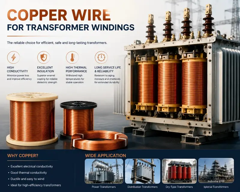
Copper wire used for winding falls under the category of specialty wire (magnet wire/winding wire), and is strictly distinguished from ordinary building wire. In the industry chain:
- Upstream: Electrolytic copper rod (8 mm copper rod or 2.6 mm fine copper rod) – Midstream: Wire drawing + enamel coating (multiple coatings + multiple baking processes) – Downstream: Transformer manufacturers, motor manufacturers, electrical equipment manufacturers
A key statistic: Globally, approximately 2 million tons of copper wire are used for winding each year, of which transformer accounts for 30%–35%.
II. Classification System of Copper Wire for transformer Windings
2.1 Classification by enamel coating type
This is the first dimension of selection. enamel coating determines thermal class and applicable scenarios.
| enamel coating type | abbreviation | thermal class | Key features |
|---|---|---|---|
| polyurethane | UEW | 130°C | It can be soldered at low temperatures (380°C) and has good direct solderability. |
| polyester | PEW | 155°C | Good heat resistance and high mechanical strength |
| polyesterimine | EIW | 180°C | Resistant to thermal shock and chemicals |
| Polyamide-imide | AIW | 200°C | High temperature resistance, refrigerant |
| polyimide | PIW | 220°C | Extremely high temperature resistance, flame retardant |
| Double-coated UEW+PEW | UEW/PEW | 155°C | Low-temperature solder + heat resistant |
Engineering Experience: For power distribution transformers, 95% use PEW/155 or EIW/180. Oil-immersed transformers must use EIW (good oil resistance). For high-frequency switching power supplies exceeding 60 kHz, PIW or special high-frequency enamel coatings are recommended.
2.2 Classification by Conductor Cross-sectional Shape
Round wire (most commonly used): – Diameter range: 0.10–7.0 mm – Applications: Low-voltage small transformers, power distribution transformers, control transformers – Advantages: Easy to draw, easy to wind, uniform enamel coating – Disadvantages: Low slot fill factor (circular space utilization is only 70%–78%)
Flat Wire / Rectangular Wire (High-Efficiency): – Thickness: 0.8–10 mm – Width: 2–25 mm – Applications: Large oil-immersed transformers, high-frequency high-power transformers, new energy vehicle drive motors – Advantages: Slot fill factor up to 85%–92%, large heat dissipation area, low skin effect loss – Disadvantages: Complex wire drawing process, difficult enamel coating, 30%–50% higher price
My experience: For transformers with a capacity exceeding 500 kVA, flat wire should be prioritized. Higher slot fill factor allows for a 10%–15% reduction in core size.
2.3 Classification by Conductor Structure
- Solid round wire: Most commonly used, high mechanical strength. – Multi-strand stranded wire (Litz wire): Dedicated for high frequencies (>100 kHz), reduces skin effect. – Copper-clad aluminum wire (CCA): Cost-sensitive, light-load transformer. – Silver-plated copper wire: High-frequency, high-temperature, oxidation-resistant applications.
2.4 Classification by Insulation Class
| Insulation class | Maximum operating temperature | enamel coating corresponds to |
|---|---|---|
| Class A | 105°C | Oil-based paint (basically phased out) |
| Class B | 130°C | UEW polyurethane |
| Class F | 155°C | PEW polyester |
| Class H | 180°C | EIW polyesterimine |
| Class N | 200°C | AIW polyamide-imide |
| Class R | 220°C | PIW (Polyimide) |
III. Detailed Explanation of Key Electrical Parameters
3.1 Conductor Resistance and Cross-sectional Area
Resistance calculation formula (20°C):
R = ρ × L / A
Where: – ρ = 1.724 × 10⁻⁸ Ω·m (copper) – L = length (m) – A = cross-sectional area (m²)
In practical engineering, the temperature coefficient must be considered: α = 0.00393 /°C (copper). Therefore, the resistivity at 75°C is 21.6% greater than that at 20°C.
A commonly used empirical value: – Resistance of 1 mm² copper wire over 1 meter length at 20°C = 0.01724 Ω – Resistance at 75°C = 0.02096 Ω – Voltage drop when 10 A current flows = 0.2096 V/m
3.2 Current Carrying Capacity and Current Density
Current density J = I / A, unit A/mm².
Typical current density values for transformer windings:
| transformer type | Current density | Remark |
|---|---|---|
| Small control transformer | 3–5 A/mm² | Good heat dissipation |
| Power distribution transformer | 4–6 A/mm² | mainstream value |
| Oil-immersed power transformer | 5–7 A/mm² | Oil cooling provides good heat dissipation |
| Dry transformer | 3–5 A/mm² | Air-cooled |
| High-frequency switch transformer | 4–8 A/mm² | Frequency has a significant impact |
Note: Lower current density results in less temperature rise, but also higher material consumption. The economical current density (considering both initial investment and operating costs) is typically 4–5 A/mm².
3.3 Skin Effect
Alternating current is not uniformly distributed in a conductor—the current concentrates at the conductor’s surface. The higher the frequency, the more pronounced the skin effect.
Skin depth formula:
δ = √(ρ / (π × f × μ))
Parameters for copper: – 50 Hz: δ = 9.4 mm – 1 kHz: δ = 2.1 mm – 10 kHz: δ = 0.66 mm – 100 kHz: δ = 0.21 mm
Impact on Transformers: – 50 Hz power frequency transformers: Skin effect is not significant when copper wire diameter < 2 mm. – Audio transformers (20 Hz–20 kHz): Moderate impact. – Switching power supply transformers (>50 kHz): Litz wire or flat wire must be used.
An interesting phenomenon: For the same cross-sectional area, flat wire has 20%–40% lower high-frequency loss than round wire—because flat wire has a larger surface area.
3.4 Proximity Effect
When multiple conductors are close together, their magnetic fields interact, causing further distortion in the current distribution. Transformer windings are multi-layered and multi-turn, making the proximity effect more pronounced than the skin effect.
Engineering Experience: – Power frequency transformers: Proximity effect losses account for approximately 5%–15% of total copper losses. – High frequency transformers: Losses can reach 30%–50%.
Solutions: interleaved winding, Litz wire, segmented winding.
IV. Mechanical Properties and Winding Process
4.1 Flexibility and Bending Performance
The transformer winding must be able to withstand repeated bending. The enamel coating must be able to withstand:
- Elongation: Copper wire ≥ 30% (soft state) / ≥ 5% (hard state) – Spring Angle: Smaller is better (< 5°) – Bending Test: Can be wound around a 1× diameter round bar without cracking.
The small bend radius of the transformer winding is typically ≥ 2 × conductor diameter. If it is smaller than this value, the risk of enamel coating cracking increases sharply.
4.2 Abrasion Resistance of enamel coating
The enamel coating is most vulnerable to scratches. This is the biggest killer of the yield rate of transformer winding manufacturing.
Factors affecting wear resistance: – enamel coating thickness (Grade 1/2/3: thin/medium/thick) – enamel coating material (PIW > AIW > EIW > PEW > UEW) – Baking process (high baking temperature, dense enamel coating) – Surface lubricant (paraffin wax, grease)
Engineering Data: Typical PEW enamel coating abrasion resistance ≥ 50 cycles (using a 600 g weight + 0.4 mm steel wire). Inferior enamel coating may withstand < 10 cycles.
4.3 Tensile Strength and Elongation
Hard copper (tensile strength ≥ 380 MPa): used for enameled round wire after drawing. Soft copper (tensile strength ≤ 250 MPa, elongation ≥ 30%): used for transformer windings.
The transformer winding must be made of soft copper. Otherwise, when winding with hard copper, the springback force will be too great, resulting in inaccurate coil dimensions and stress concentration.
4.4 Key Points of Winding Process
The winding process directly affects the quality of the transformer.
Winding Tension Control: – Excessive tension: thins the copper wire, damages the enamel coating. – Insufficient tension: loose coil, unstable inter-turn capacitance. – Typical tension: 5–30 g (depending on wire diameter)
Winding speed: – round wire: 10–30 m/s – flat wire: 1–5 m/s (slower, to avoid damage to enamel coating)
Mold Selection: – Use a round tension wheel for round wire – Use a flat mold for flat wire – The mold surface must be polished (Ra < 0.4 μm)
Workshop Environment: – Temperature 20–30°C – Humidity 40%–60% – Dust control (Class 100,000 cleanliness)
I once encountered a client whose winding workshop had excessive dust levels, an enamel coating scratch rate as high as 5%, and a transformer first-pass yield of less than 80%. After installing air filtration equipment, the pass rate increased to 98%.
V. Temperature and Heat Dissipation Design
5.1 Relationship between Temperature Rise and Lifespan
The lifespan of a transformer follows the Arrhenius equation:
L = A × exp(E / kT)
Simply put: For every 10°C increase in temperature, lifespan is halved (rule of thumb).
This is why transformer design requires strict control over hotspot temperatures:
| Insulation class | Highest hotspot temperature | Life expectancy |
|---|---|---|
| Class A | 105°C | 20–30 years |
| Class B | 130°C | 20–25 years |
| Class F | 155°C | 20–25 years |
| Class H | 180°C | 15–20 years |
The power distribution transformer has a design life of 30 years, a temperature rise limit of 65K (oil surface temperature rise), and a winding hot spot temperature ≤ 95°C.
5.2 The Influence of Heat Dissipation Method on Copper Wire Selection
| Heat dissipation method | Applicable to transformer | Current density |
|---|---|---|
| Natural oil cooling (ONAN) | Power distribution transformer | 4–6 A/mm² |
| Forced oil cooling (ONAF) | Electricity transformer | 5–7 A/mm² |
| Forced oil circulation (OFAF) | Large power transformer | 6–8 A/mm² |
| Dry natural air cooling (AN) | Dry transformer | 3–5 A/mm² |
| Dry forced air cooling (AF) | Dry transformer | 4–6 A/mm² |
| Water cooling | Special transformer | 8–12 A/mm² |
Engineering Experience: For every level improvement in heat dissipation, the capacity of a transformer can increase by 20%–40%—this is why large power transformers use forced oil circulation.
5.3 Measurement of Hot Spot Temperature
Hot spot temperature is the most difficult to measure, but also the most crucial:
- Direct Measurement: Embedded thermocouple (high cost, only used in critical equipment) – Fiber Optic Temperature Measurement: Fiber optic sensor embedded inside the transformer (accuracy ±1°C) – Empirical Estimation: Hot spot temperature ≈ Oil surface temperature rise × 1.1–1.3
IEC 60076 Standard: The hot spot temperature of the power distribution transformer shall not exceed 95°C (oil immersion) or 130°C (dry type, Class B).
5.4 Performance Changes of Copper Wire at Different Temperatures
- Softening Temperature: 200°C (Sustainable in the short term, will anneal in the long term) – Decomposition of enamel coating: Polyurethane 180°C, Polyester 220°C, Polyimide 400°C – Temperature Coefficient of Resistance: +0.393%/°C (Resistance increases with temperature)
Sufficient temperature rise margin must be allowed in the design. Class F insulation (155°C) winding actual operating temperature ≤ 130°C — this ensures a safety margin of 25K.
VI. transformer Insulation System
6.1 Insulation Class and enamel coating selection
The transformer insulation system consists of multiple layers of insulation:
- Conductor enamelled coating (copper wire enamel coating) 2. Inter-turn insulation (enamel coating itself) 3. Interlayer insulation (insulating paper/polyester film) 4. Main insulation (insulating cylinder, support strip, spacer) 5. Oil channel (insulating oil or air)
The copper wire (enamel coating) serves as the inter-turn insulation – this is the weakest and most critical link.
Breakdown Voltage Requirements: – Double-coated round wire ≥ 3.5 kV (1 min immersion in water) – Triple-coated round wire ≥ 5 kV – Test voltage: IEC 60851 standard
6.2 Special Requirements for Oil-Immersed Transformers
Oil-immersed transformer/enamel coating must be oil-resistant.
- PU Paint (UEW): Poor oil resistance, not recommended. – PEW Paint: Moderate oil resistance, barely usable. – EIW Paint: Good oil resistance, the first choice for oil-immersed transformers. – AIW Paint: Excellent oil resistance, used for special oil-immersed transformers.
Mineral oil (transformer) slowly penetrates enamel coating at temperatures of 80–100°C. Polyester imine enamel coatings are 5–10 times more oil-resistant than polyurethane coatings.
6.3 Special Requirements for Dry Transformers
Dry-type transformers rely on air for insulation, and their enamel coating must be flame-retardant.
- Flame retardant rating: UL 94 V-0 – Low smoke halogen-free (LSZH) requirement – enamel coating must not produce toxic gases (in case of fire)
Dry-cast epoxy transformer (24 kV–35 kV) Uses enameled wire + vacuum-cast epoxy. The enamel coating must have good adhesion to the epoxy resin—both PEW and EIW are suitable.
6.4 Insulation Aging Detection
After 20 years of operation, the copper wire enamel coating may age.
- Appearance Inspection: Enemy coating color darkening, blistering, peeling. – Electrical Inspection: Decreased insulation resistance, increased dielectric loss (tan δ). – Chemical Inspection: Furfural content in oil (oil immersion transformer, >4 mg/L alarm).
State Grid Corporation Standard: For oil-immersed transformers that have been in operation for more than 20 years, an insulating oil chromatographic analysis should be performed every 3 years.
VII. Correspondence Table between transformer Types and Copper Wire Selection
7.1 Power Transformer
The term “electric transformer” refers to a large transformer with a capacity of 35 kV–500 kV and above 50 MVA.
Copper Wire Selection: – Flat wire (thickness 1.0–5.0 mm, width 5–20 mm) – EIW enamel coating (180°C) or AIW enamel coating (200°C) – Transposed conductor (CTC, continuously transposed conductor) – Large single wire diameter, few winding layers
Typical Project: 500 kV power transformer low-voltage winding using 2.5 × 12 mm copper flat wire with AIW enamel coating, current density 5.5 A/mm².
7.2 Distribution Transformer
Power distribution transformer 10 kV / 0.4 kV, capacity 50 kVA–2500 kVA.
Copper Wire Selection: – Round wire (diameter 1.5–5.0 mm) – PEW (enamel coating) (155°C) or EIW (enamel coating) (180°C) – Single-layer cylindrical winding – Oil-immersed or dry-type
Typical Project: 1000 kVA oil-immersed transformer high-voltage winding with PEW enameled round wire Φ2.5 mm, current density 4.5 A/mm².
7.3 High-Frequency Switching Power Supply transformer
Operating frequency 20 kHz–500 kHz, capacity 100 W–50 kW.
Copper Wire Selection: – Litz wire (multi-strand stranded wire, 0.05–0.20 mm per strand) – PIW (enamel coating) (220°C) or special high-frequency enamel coating – High-temperature resistance plastics such as PBT, PPS, and LCP for the skeleton – Ferrite, amorphous, or nanocrystalline core
Key Design Features: Single strand diameter ≤ skin depth (δ = 0.21 mm at 100 kHz). Litz wire can be made of 1000 strands of Φ0.05 mm twisted together.
7.4 Rectifier transformer and Electric Furnace transformer
The rectifier transformer outputs DC, which is used in electroplating, electrolysis, and electric furnaces.
Copper Wire Selection: – Round wire or flat wire – Enamelled coating thickness Grade 2 (medium) – Short-circuit withstand capability (short-circuit impedance 8%–12%)
Electric furnaces draw extremely high currents (tens of thousands of amperes) and often use copper busbars or copper tubes (hollow copper tubes cooled by water).
7.5 New Energy transformer (Photovoltaic/Wind Power)
Photovoltaic power and wind power require high efficiency and low loss.
Copper Wire Selection: – High-purity oxygen-free copper (OFC) – Low-loss enamel coating (PEW or EIW) – Tightly coupled structure (low leakage flux) – Operating frequency 1–20 kHz
Typical Project: 1 MW photovoltaic inverter/transformer, 10 kHz frequency, 6 A/mm² current density, using oxygen-free copper PEW wire.
7.6 charging stationtransformer
Electric vehicle (OBC), power 3.3 kW–22 kW.
Copper Wire Selection: – High-frequency Litz wire (50–500 kHz) – PIW (enamel coating) (high temperature resistance) – Planar core structure (PCB embedding) – High efficiency (>95%)
7.7 Specialty transformer (medical, railway, aviation)
- Medical Transformer (MRI Compatible): Ultra-low noise, copper wire must be free of magnetic impurities. Railway Traction Transformer: Vibration resistant, enamel coating must be dense. Aerospace Transformer: Ultra-lightweight, aluminum enameled wire or copper flat wire.
VIII. Procurement and Acceptance Guidelines
8.1 List of Core Selection Elements
When purchasing copper wire for transformer windings, eight core parameters must be considered:
- Conductor Material: Pure Copper TU1 / Oxygen-Free Copper OFHC / Copper-Clad Aluminum CCA 2. Conductor Specifications: Round wire diameter (mm) or Flat wire thickness × width (mm) 3. Enamellable Coating Type: UEW / PEW / EIW / AIW / PIW 4. Thermal Class: Class 130 / 155 / 180 / 200 / 220 5. Enamellable Coating Grade: Grade 1 (Thin) / Grade 2 (Medium) / Grade 3 (Thick) 6. Standards: IEC 60317 / NEMA MW 1000 / GB/T 6109 7. Packaging Specifications: Spool weight (30 kg / 60 kg / 150 kg) 8. Certification Requirements: UL / REACH / RoHS / IECQ
8.2 Incoming Quality Control (IQC) Items
| Inspection items | method | standard |
|---|---|---|
| conductor diameter | micrometer | ±0.005 mm |
| enamel coating thickness | Microthickness Measurement | IEEE 57 / IEC 60851 |
| enamel coating continuity | Pinhole test | < 5 holes / 30 m |
| DC resistance | resistance bridge | ≤ 0.01724 Ω·mm²/m |
| Breakdown voltage | High voltage test | ≥ 3.5 kV (double coating) |
| Softening and Breakdown | Oven + Breakdown | ≥ 200°C (according to enamel coating) |
| Solderability | 380°C Immersion Tin | Paint peeling in ≤ 3 seconds |
| elongation | Tensile test | ≥ 30% (soft state) |
8.3 Common Quality Problems and Countermeasures
Issue 1: Bubbling of the enamel coating – Cause: Insufficient baking temperature, residual solvent in the enamel coating – Solution: Return to factory for re-baking / Return the product
Problem 2: Copper wire turns black – Cause: Copper rod oxidation, poor conductor quality – Solution: Test copper content (≥ 99.95%), annealing treatment
Issue 3: Scratches on the enamel coating – Causes: Transportation collisions, rough mold – Solutions: Change transportation method, polish the mold
Issue 4: Resistance Exceeds Standard – Causes: Insufficient conductor cross-sectional area, poor copper rod quality – Solution: 100% random inspection of resistors; returns of batches exceeding standards.
8.4 Key Points for Supplier Evaluation
When selecting a supplier, don’t just look at the price; consider these five factors:
- Quality Management System: ISO 9001, ISO 14001, ISO 45001 2. Production Equipment: Imported coating machines (Italy SICME, Germany MAG, etc.) 3. Testing Capabilities: Own laboratory, third-party testing reports 4. Industry Experience: ≥ 10 years of experience in winding wire production 5. Client Cases: Collaborations with major power transformer manufacturers and major wind/solar power manufacturers
A lesson learned: A stable supplier is more important than one that is 10% cheaper. Transformers are long-life equipment, lasting 20-30 years; poor-quality raw materials will cause problems constantly.
8.5 Cost and Price Range
Price gradient of copper wire for transformer windings of the same weight:
| enamel coating | Relative Price (Copper Wire Base) |
|---|---|
| Pure copper (without enamel coating) | 1.0× |
| UEW/130 | 1.05–1.10× |
| PEW/155 | 1.15–1.25× |
| EIW/180 | 1.30–1.45× |
| AIW/200 | 1.50–1.70× |
| PIW/220 | 1.80–2.20× |
Flat wire is 30%–50% more expensive than round wire, and Litz wire is 50%–100% more expensive (depending on the number of strands).
Engineering Experience: Copper wire accounts for 15%–25% of the total cost of a transformer. When selecting a transformer, you shouldn’t just look at the unit price, but also at the overall cost (materials + losses + lifespan).
In short: Using copper wire for transformer windings is a systematic engineering project—conductivity, insulation, heat dissipation, mechanics, and environmental resistance are all crucial and cannot be compromised. When selecting a wire, all eight engineering elements (material, enamel coating, specifications, mechanics, temperature, insulation, application, and inspection) must be considered holistically; one cannot focus on just one parameter.