


Enameled wire is one of the most fundamental and widely used winding conductor forms in the electrical industry. It consists of a copper or aluminum core conductor coated with one or more layers of insulating enamel, which—after curing—forms a continuous, thin, and highly adherent insulation layer. Although the enamel film thickness is typically only several tens of micrometers, it fulfills critical insulation functions: turn-to-turn insulation, phase-to-phase insulation, and insulation to ground. A systematic analysis of enameled wire advantages requires evaluation across multiple dimensions: electrical performance, thermal performance, mechanical performance, chemical resistance, processability, and whole-life-cycle economic efficiency. This article discusses the core technical advantages of enameled wire in accordance with internationally and nationally recognized standards—including IEC 60317, NEMA MW 1000, IEC 60085, IEC 60216, and GB/T 6109—covering dielectric properties of the enamel film, thermal life rating, mechanical strength, chemical resistance, winding processability, space utilization, electrical efficiency, reliability and maintainability, cost-effectiveness, and sustainability, thereby providing technical reference for winding design, motor selection, transformer applications, and electrical equipment development.
Dielectric Performance and Insulation Reliability
Although the insulation layer of magnet wire is extremely thin, it can withstand electric field stress over extended periods under operating voltage without breakdown—this is the fundamental prerequisite enabling its widespread use in low-voltage windings. Dielectric strength of the enamel film is typically expressed in kV/mm or V/μm; the breakdown voltage of conventional polyester magnet wire can reach several tens of kV/mm—approximately dozens of times that of air at equivalent thickness. Breakdown voltage increases linearly with enamel film thickness and uniformity. The IEC 60317 series standards specify minimum breakdown voltage requirements for different enamel grades—for example, Grade 1, Grade 2, and Grade 3 correspond to incremental enamel thicknesses and thus distinct insulation levels. In turn-to-turn insulation applications, the dielectric strength of magnet wire directly determines the peak phase voltage the winding can withstand, as well as high-frequency voltage surges generated by PWM variable-frequency power supplies.
Breakdown Voltage and Dielectric Strength
Breakdown voltage is one of the most critical electrical parameters of magnet wire. It quantifies the enamel film’s ability to resist dielectric breakdown under progressively increasing voltage. Breakdown voltage increases linearly with enamel film thickness; enamel film uniformity, adhesion between enamel and conductor, and presence of pinholes or impurities within the enamel all directly affect the actual breakdown voltage. Standards such as IEC 60317-1 and IEC 60317-2 define test methods for enamel continuity, breakdown voltage, and pinhole count. Conductor surface pretreatment quality (annealing, cleaning) constitutes a prerequisite condition affecting enamel integrity; residual drawing lubricants or oxide layers on the conductor surface create weak points within the enamel film.
Partial Discharge and Pulse Withstand
In PWM variable-frequency drive systems, motor windings are subjected to voltage waveforms exhibiting high dv/dt and significant high-frequency components; conventional power-frequency insulation may experience partial discharge under pulse conditions. Magnet wire’s pulse withstand capability is closely related to the enamel material system, enamel thickness, and conductor corner radius. Enamel systems such as polyester-imide and polyamide-imide exhibit superior pulse life compared to pure polyester, making them especially suitable for variable-frequency motor windings. Partial Discharge Inception Voltage (PDIV) and Partial Discharge Extinction Voltage (PDEV) have become key reference parameters for magnet wire selection in variable-frequency motor windings. The presence of conductor edges induces electric field concentration; round conductors achieve more uniform electric field distribution than shaped conductors.
Insulation Resistance and Leakage Current
Insulation resistance reflects the leakage current level of magnet wire under DC voltage, typically on the order of GΩ·m or higher. Higher insulation resistance results in lower leakage current and lower dielectric loss in windings operating at rated voltage. Factors influencing insulation resistance include enamel chemical composition, degree of cure, ambient humidity, and temperature. Humidity-sensitive enamel systems exhibit significant reduction in insulation resistance under humid conditions, necessitating mitigation via sealing, impregnation, or composite insulation structures. During long-term operation, enamel aging leads to progressive decline in insulation resistance—this parameter serves as one of the key indicators for winding lifetime prediction.
Thermal Performance and Thermal Endurance
The thermal class of magnet wire directly determines its maximum operating temperature and expected service life in motors, transformers, and other equipment. IEC 60085 classifies electrical insulation into multiple thermal classes—Y, A, E, B, F, H, N, and R—each corresponding to a reference operating temperature and associated thermal life curve. The chemical structure of the enamel determines its thermal endurance; thermal stability varies among ester, amide, imide, and polyimide linkages. Magnet wire thermal life follows the Arrhenius empirical relationship: for every 8–10 K increase in temperature, thermal life is approximately halved—a principle adopted by IEC 60216 for thermal life evaluation.
Thermal Classification and Temperature Index
Typical thermal classes and corresponding enamel systems are as follows: polyester magnet wire generally corresponds to Class 130 or Class 155; polyester-imide magnet wire to Class 180; polyamide-imide magnet wire to Class 200; and polyimide magnet wire to Class 220 or higher. Under the IEC 60085 standard system, each thermal class corresponds to a reference operating temperature—for example, Class B: 130 ℃, Class F: 155 ℃, Class H: 180 ℃, Class N: 200 ℃, and Class R: 220 ℃. It should be noted that increasing the operating temperature requires not only that the enamel possess matching thermal endurance but also that other insulating materials external to the conductor enamel—such as impregnating varnish, slot liners, and tie bands—exhibit compatible thermal classes; otherwise, system-level thermal bottlenecks may occur.
Arrhenius Thermal Aging
The Arrhenius thermal aging model serves as the theoretical foundation for magnet wire thermal life evaluation. This model assumes that the rate constant of chemical reactions varies exponentially with temperature; thus, enamel aging rate increases exponentially with rising temperature. The IEC 60216 series standards specify thermal life evaluation methods based on the Arrhenius model. A typical test procedure involves long-term aging of magnet wire samples at multiple constant-temperature points, with periodic measurement of breakdown voltage or flexibility to determine time-to-failure and thereby derive the thermal life curve. In practical engineering applications, the thermal life model is widely employed for design-life prediction of motors and transformers, as well as for calculating operational temperature margins.
Heat Shock Resistance and Thermal Cycling
Winding wire undergoes rapid temperature changes during winding insertion, impregnation, and operation. Thermal shock induces interfacial stress between the enamel and conductor; if the enamel’s coefficient of thermal expansion mismatches that of copper or aluminum, or if the enamel lacks sufficient flexibility, cracking or delamination may occur. Approaches to improve heat shock resistance include optimizing enamel elastic modulus, incorporating flexible molecular groups, and lowering the enamel’s glass transition temperature (Tg). Polyamide-imide, owing to its excellent flexibility, is commonly applied as a topcoat over a polyester-imide basecoat to form a composite coating, thereby achieving dual advantages of high thermal endurance and superior heat shock resistance. Furthermore, the heating and cooling rates during winding impregnation must be compatible with the enamel’s heat shock capability to prevent process-induced insulation damage.
Mechanical Properties and Winding Processability
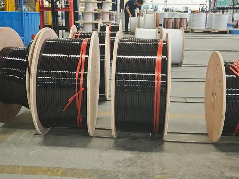
Enameled wire must withstand multiple mechanical operations during manufacturing, including wire drawing, take-up, pay-off, storage and transportation, winding, coil insertion, shaping, and tying. The enamel coating must remain intact not only under final operating conditions but also during manufacturing—withstanding tensile stress, bending, abrasion, and impact without cracking or flaking. Mechanical properties of the enamel coating are typically characterized by elongation, flexibility, adhesion, abrasion resistance, and spring back. The IEC 60317 series standards specify quantitative requirements for mechanical properties of enameled wire, differentiated by conductor diameter and enamel grade.
Elongation and Flexibility
Elongation reflects the ability of the enamel coating and conductor to deform cohesively under tensile stress. Excessively low elongation indicates high brittleness of the enamel, increasing susceptibility to cracking during bending or stretching; excessively high elongation may compromise dielectric strength and thermal endurance. Per IEC 60317, minimum elongation for enameled wire is typically specified at ≥10%–25%, with specific values dependent on conductor diameter. The mandrel wrap test is a common method for evaluating enamel flexibility: the wire is wrapped for a specified number of turns around a cylindrical mandrel with a diameter equal to or several times the wire diameter, followed by visual inspection for enamel cracking. Finer-diameter wires impose higher demands on enamel flexibility due to increased localized bending stress during winding of small-dimension coils.
Adhesion and Peel Resistance
Adhesion between the enamel coating and conductor is one of the core mechanical performance indicators for enameled wire. Insufficient adhesion may result in delamination of the enamel from the conductor during winding or shaping, creating insulation weak points. Key factors influencing adhesion include conductor surface pretreatment condition, enamel chemical composition, curing process parameters, and compatibility between base coat and top coat. Residual oils, oxides, or particulate contamination on the conductor surface significantly reduce enamel adhesion. Base coat selection critically affects adhesion performance; polyester-based base coats generally exhibit excellent compatibility with copper conductors. IEC 60317 specifies standardized test methods for enamel adhesion, including the rapid pull test and peel test.
Abrasion Resistance and Scratch Hardness
Abrasion resistance is a critical parameter for enameled wire subjected to automated winding and coil insertion processes, where mechanical damage must be minimized. During high-speed winding, the wire experiences continuous friction against guide nozzles, tensioners, wire clamps, and winding dies; enamel wear can lead to insulation failure. Abrasion resistance is commonly quantified by the number of cycles required to wear through the enamel or by the applied scratch force. Enhancement strategies include optimizing enamel chemical structure, increasing crosslink density, and employing multi-layer composite coatings. Polyamide-imide (PAI) topcoats significantly improve abrasion resistance and are widely adopted for automated winding applications. While enamel hardness correlates with abrasion resistance, excessive hardness compromises flexibility—requiring balanced optimization.
Spring back and Winding Tension
Spring back refers to the tendency of enameled wire to recover its original shape following bending deformation. Excessive spring back impedes precise coil formation, particularly in micro-motors and precision instruments demanding tight dimensional tolerances. Influencing factors include conductor material (copper, aluminum, and their alloys), conductor diameter, enamel elastic modulus, and winding tension. Aluminum conductors typically exhibit greater spring back than copper conductors, necessitating compensation via tension control and die design in winding processes. The viscoelastic behavior of the enamel coating also affects spring back characteristics; enamel softening at elevated temperatures alters the dimensional stability of wound coils.
Chemical Resistance and Environmental Adaptability
Enameled wire may come into contact with various chemical media during use, transportation, and storage, including lubricating oils, coolants, cleaning agents, impregnating varnishes, fluxes, moisture, salt spray, acids, and alkalis. The enamel coating’s resistance to such chemical media determines the wire’s suitability for diverse application environments. Chemical attack can cause enamel swelling, softening, cracking, and reduced adhesion, ultimately leading to electrical failure.
Resistance to Oils and Solvents
Impregnating varnishes, diluents, and cleaning agents commonly used in winding impregnation processes exert strong chemical effects on the enamel coating. Enameled wire must withstand these process media without enamel softening, blistering, or delamination. Polyester-imide, polyamide-imide, and polyimide enamel systems exhibit excellent resistance to common organic solvents. In specific industrial applications—such as transformer oil environments—the wire must endure prolonged immersion in mineral oil or synthetic ester oil without enamel swelling or performance degradation. IEC 60851 specifies the test method for solvent resistance of enameled wire.
Resistance to Moisture and Hydrolysis
Humid environments significantly affect the dielectric and mechanical properties of the enamel coating. Moisture absorption reduces insulation resistance and increases dielectric loss; prolonged exposure may induce hydrolytic degradation of the enamel. Moisture and heat resistance is a critical performance indicator for enameled wire applications in tropical and maritime climates. Approaches to enhance moisture and heat resistance include optimizing the enamel’s chemical structure, incorporating hydrophobic functional groups, and increasing crosslink density. Due to its exceptional chemical stability, polyimide enamel exhibits outstanding resistance to humid environments. During storage, environmental humidity must be controlled to prevent long-term exposure to high-humidity conditions that could degrade enamel performance.
Resistance to Refrigerants and Coolants
In household appliances, industrial refrigeration, and automotive air-conditioning systems, enameled wire must withstand prolonged contact with refrigerants and coolants. Chemical compatibility between the enamel coating and refrigerants (e.g., R134a, R410A, R32) and refrigeration lubricants (e.g., PAG, POE, PVE) requires dedicated validation. Contact with refrigerants and lubricating oils must not result in significant enamel swelling, performance deterioration, or leaching reactions. In new-energy vehicle traction motors and battery cooling systems, enameled wire may also contact coolant media such as ethylene glycol–water solutions; chemical resistance is thus an essential selection criterion.
Slot Fill, Space Efficiency, and Winding Compactness
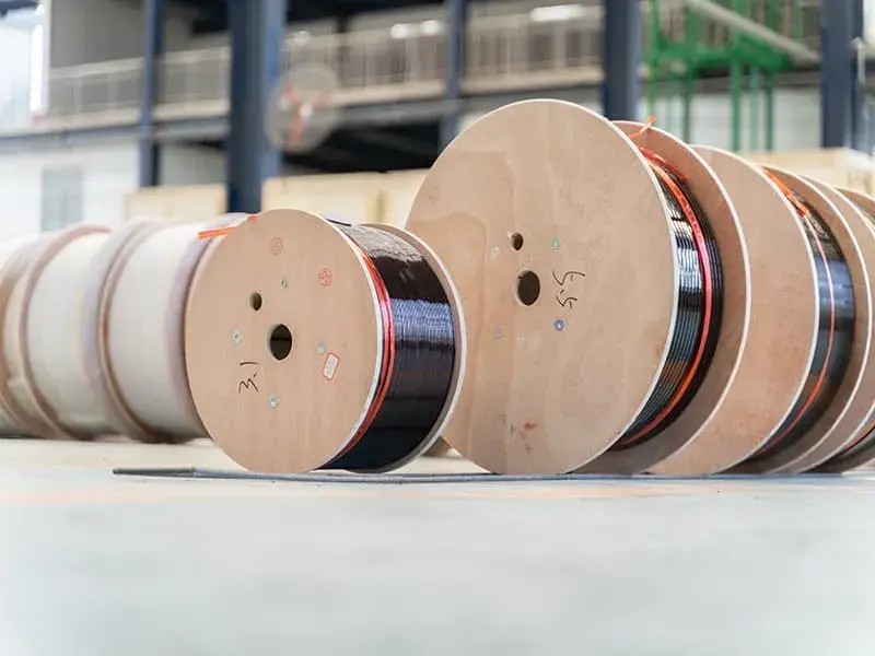
The thin insulation of magnet wire confers significant advantages in slot fill factor, space efficiency, and winding compactness. Compared with wrapped insulation systems—such as fiber wrapping (glass yarn, cotton yarn, paper), mica tape wrapping, or film wrapping—the enamel coating thickness is only one-tenth to one-fortieth that of such alternatives, enabling a substantially larger conductor cross-sectional area to be accommodated within a given slot volume. Improved slot fill directly translates into higher equipment power density, reduced conductor losses, and lower material costs.
Comparison with Wrapped Insulation
Traditional wrapped insulation employs fibers (e.g., glass yarn, cotton yarn, paper) or films (e.g., polyester film, mica tape, polyimide film) helically wrapped around the conductor; insulation thickness typically ranges from 0.1 mm to 1 mm. In contrast, the enamel coating thickness of magnet wire generally falls within the range of 0.02 mm to 0.10 mm. For identical slot dimensions, magnet wire accommodates a significantly greater conductor cross-sectional area than wrapped-insulated conductors. This advantage is critical for miniaturized, lightweight, and high-power-density motor designs. Wrapped insulation excels in mechanical strength and high-temperature resistance, and is predominantly used in large power transformers, high-voltage motors, and traction motors.
Round Wire and Rectangular Wire Geometry
Magnet wire is categorized by cross-sectional geometry into round magnet wire and rectangular (flat) magnet wire. Round magnet wire is the most widely applied form, with standard diameters spanning 0.016 mm to 7.0 mm. Rectangular magnet wire is employed in high-power-density motors and transformers—particularly in hairpin windings for new-energy vehicle (NEV) traction motors and continuously transposed conductors (CTC) in transformers. Rectangular wire offers superior space utilization compared to round wire, but its winding process and insulation handling are more complex. Uniform enamel coverage at the sharp edges and corners of rectangular wire represents a key manufacturing challenge, requiring optimization of the enameling process, primer selection, and conductor edge chamfering.
Slot Fill Factor and Power Density
Slot fill factor is a core economic performance indicator in magnet wire applications. It is defined as the ratio of the total conductor cross-sectional area to the available slot cross-sectional area, typically ranging from 40% to 80%. A higher slot fill factor enables greater conductor volume per unit slot area, thereby increasing equipment power density and efficiency. Actual slot fill is influenced by enamel thickness, conductor packing configuration (random winding, ordered winding, diamond winding), and coil insertion (wedging) technique. The thin enamel coating of magnet wire facilitates high-slot-fill designs; however, it also imposes higher requirements on enamel abrasion resistance and mechanical damage resistance, since the enamel must withstand significantly increased friction forces during the coil insertion process.
Electrical Efficiency, Conductivity, and Skin Effect
The inner conductor of magnet wire is made of copper or aluminum; the electrical conductivity of copper is approximately 58 MS/m, while that of aluminum is approximately 36 MS/m. Copper conductors offer significant advantages in high-current applications, whereas aluminum conductors are advantageous in weight-sensitive and cost-sensitive applications. The electrical conductivity of magnet wire directly affects winding copper losses, temperature rise, and overall equipment efficiency.
Copper vs. Aluminum Conductors
Copper conductors feature low resistivity, high mechanical strength, and excellent solderability, making them the preferred choice for windings in the vast majority of motors and transformers. Aluminum conductors possess a density approximately one-third that of copper, with low weight being their primary advantage; aluminum is also less expensive than copper and is widely used in large power transformers and transmission lines. Aluminum surfaces readily form an aluminum oxide layer, requiring specialized processes for welding and termination. Enameled aluminum wire requires a dedicated primer to enhance enamel film adhesion and prevent weak interfaces between the enamel coating and the aluminum oxide layer. The IEC 60317 series standards contain specific provisions for enameled aluminum wire.
Skin Effect and Proximity Effect at High Frequency
In high-frequency applications, current distribution across the conductor cross-section becomes non-uniform, with current density concentrated near the conductor surface—this phenomenon is known as the skin effect. Skin depth is inversely proportional to the square root of frequency: higher frequencies result in smaller skin depths. Litz wire—comprising multiple individually enameled fine wires twisted together—is commonly employed in high-frequency applications to effectively reduce skin-effect losses. Each strand in Litz wire must be fully insulated by enamel coating to prevent inter-strand short circuits. Enamel coating uniformity and integrity are critical to the electrical performance of Litz wire. Litz wire is extensively used in switch-mode power supply transformers, wireless charging coupling coils, and high-frequency inductors.
Dielectric Loss and tanδ
The dielectric loss tangent (tanδ) of the enamel coating quantifies energy dissipation under alternating electric fields. A lower tanδ value corresponds to reduced dielectric losses in AC windings and higher system efficiency. tanδ is influenced by enamel chemical composition, temperature, and frequency. Non-polar materials such as polypropylene and polyethylene exhibit extremely low tanδ values and are suitable for high-frequency applications; polar materials such as polyester and polyimide exhibit relatively higher tanδ values but remain acceptable for power-frequency applications. The tanδ versus temperature curve of magnet wire serves as a key indicator for assessing thermal aging.
Winding Process Compatibility and Manufacturing Efficiency
Enameled wire has become a standardized foundational material in modern electrical manufacturing; its process compatibility directly impacts production efficiency, capacity stability, and winding quality. The advantages of enameled wire extend beyond final performance to include process convenience during manufacturing—such as high-speed winding, automated insertion, automated soldering, and impregnation/curing.
High-Speed Winding Compatibility
Modern winding machines achieve wire speeds of several tens of meters per second or higher. Enameled wire must withstand friction, tensile force, and tension fluctuations during high-speed winding without enamel film damage. Key requirements for high-speed winding include enamel film abrasion resistance, lubricity, and surface smoothness. Enamel surfaces typically contain trace amounts of lubricants (e.g., paraffin wax, synthetic waxes) to reduce winding friction. Polyamide-imide (PAI) topcoats are commonly selected for high-speed winding due to their excellent abrasion resistance and lubricity. Precise tension control is also critical: excessive tension may cause enamel film stretching damage, while insufficient tension may result in loose coil winding.
Impregnation Compatibility
After winding insertion, the coil assembly undergoes impregnation treatment using impregnating varnish to fill air gaps within the winding, thereby enhancing overall insulation performance, thermal conductivity, and mechanical strength. The enameled wire must exhibit good compatibility with the selected impregnating varnish; the enamel film must not swell, blister, or delaminate upon exposure to solvents in the impregnating varnish. Common impregnating varnish systems include epoxy resins, polyester resins, silicone resins, and polyurethane resins. Vacuum Pressure Impregnation (VPI) is a widely adopted impregnation method for high-voltage motors and transformers, imposing stringent demands on the chemical resistance of the enamelled wire.
Termination and Solderability
After coil formation, the enameled wire must be terminated at the coil terminals and connected to external circuits via methods including soldering, crimping, wrapping, or fusion bonding. Soldering is the most widely applied termination method; the enamel film at the wire end must be removed to expose the conductor surface prior to soldering. Common enamel removal techniques include mechanical scraping, chemical stripping, thermal melting, and laser ablation. Enamel removability is a critical consideration in enamelled wire manufacturing; excessively high adhesion may significantly increase removal difficulty. Polyurethane enamelled wire (UEW), owing to its inherent solderability, allows direct removal of the end-coating enamel using a hot soldering iron—eliminating the need for additional mechanical or chemical processing—and thereby substantially improving manufacturing efficiency.
Reliability, Service Life and Maintenance Characteristics
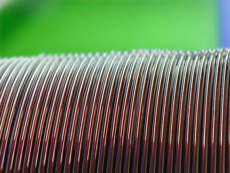
The reliability of magnet wire is defined as its ability to maintain electrical, mechanical, thermal, and chemical performance over extended periods under specified operating conditions without failure. Reliability constitutes the core competitive advantage of magnet wire as a fundamental component and is the fundamental reason for its widespread adoption in demanding industrial applications.
Long-Term Aging Behavior
During long-term operation, magnet wire is subjected to combined stresses—including temperature, humidity, electric field, mechanical vibration, and chemical media—resulting in coupled aging modes such as thermal aging, electrical aging, mechanical aging, and chemical aging. Standards IEC 60172 and IEC 60216 specify accelerated aging test methods based on single or multiple stresses for evaluating the long-term reliability of magnet wire. In practical engineering applications, the design service life of magnet wire must meet the overall equipment lifetime requirements—for example, 10 years for household appliances, 20 years for industrial motors, and 30 years for transformers—across different application classes. Reliability models for magnet wire require correction according to the specific operational conditions of the equipment.
Failure Modes and Diagnostic Indicators
Primary failure modes of magnet wire include insulation film breakdown, cracking, delamination, swelling, and conductor corrosion. Insulation film breakdown is typically caused by overvoltage, partial discharge, or cumulative thermal aging; cracking and delamination arise mainly from mechanical stress, thermal shock, or insufficient adhesion; swelling results primarily from chemical media attack; and conductor corrosion stems from moisture or acidic/alkaline medium ingress. Common diagnostic indicators for assessing magnet wire aging include breakdown voltage, insulation resistance, tanδ, Partial Discharge Inception Voltage (PDIV), and Partial Discharge Extinction Voltage (PDEV). Regular monitoring of these parameters enables evaluation of winding residual life and formulation of preventive maintenance plans.
Maintenance and Rewinding Convenience
When windings fail, motors or transformers typically require rewinding. The rewinding process convenience depends on the magnet wire’s windability, impregnability, and solderability. The insulation film must not suffer excessive damage during winding and shaping operations, and the rewound winding must fully restore its original insulation performance. Magnet wire is highly standardized with comprehensive product specifications, facilitating easy procurement from the market and simplifying maintenance supply chains. Storage stability is also a critical aspect of maintenance convenience: appropriate storage conditions—controlled temperature, humidity, and avoidance of direct sunlight—ensure that magnet wire retains stable performance over multi-year storage periods.
Cost Efficiency and Sustainability Considerations
The total cost of magnet wire encompasses not only material costs but also manufacturing process costs, equipment occupancy costs, energy consumption costs, maintenance costs, and end-of-life disposal costs. As a high-volume industrial product, magnet wire achieves cost advantages based on mature manufacturing processes, a well-established supply chain, and a standardized product system.
Material and Manufacturing Cost
The primary cost components of copper magnet wire include copper material cost, enamel cost, energy cost, labor cost, and equipment depreciation cost. Copper price volatility significantly impacts magnet wire cost; aluminum magnet wire offers cost advantages in weight-insensitive applications due to aluminum’s lower raw material cost. Enamel cost depends on the enamel system—high-end systems such as polyimide entail substantially higher costs than standard polyester systems. The continuous production process for magnet wire is highly mature, with high single-line capacity; unit manufacturing cost decreases with economies of scale. International standards such as NEMA MW 1000 and IEC 60317 provide unified specifications for magnet wire dimensions, procurement, and inspection, thereby reducing transaction costs.
Lifecycle and Sustainability
Lifecycle assessment (LCA) of magnet wire must account for environmental impacts across all stages: raw material extraction, manufacturing, in-service operation, and end-of-life disposal. Copper, being recyclable, can be recovered from scrap magnet wire at recovery rates exceeding 95% after enamel removal via incineration. Aluminum recycling consumes far less energy than primary aluminum production, delivering significant economic benefits. Environmental performance of enamel materials is increasingly critical; lead-free, heavy-metal-free, and low-VOC enamel systems represent the industry’s developmental direction. International regulatory frameworks—including REACH, RoHS, and UL—impose explicit environmental requirements on magnet wire, serving as essential market access criteria for international trade.
Total Cost of Ownership
From a total cost of ownership (TCO) perspective, magnet wire’s value extends beyond initial purchase price to encompass operational energy consumption, maintenance requirements, and service life over the equipment’s lifetime. High slot-fill designs reduce material usage per unit of equipment; high electrical conductivity minimizes operational losses; extended service life reduces replacement frequency; and standardization lowers maintenance costs. Holistically, magnet wire delivers optimal TCO across most application scenarios—a benefit particularly pronounced in large-scale industries such as new-energy vehicle traction motors, household appliances, wind-power converters, and photovoltaic inverters.
Concluding Synthesis on Engineering Trade-offs
The advantages of magnet wire are comprehensive, spanning electrical, thermal, mechanical, chemical, processing, economic, and sustainability dimensions. Magnet wire is typically the preferred winding conductor in applications requiring low-voltage windings, compact designs, automated production, and extended service life. Selection of magnet wire necessitates a holistic trade-off among thermal class, insulation film thickness, mechanical strength, chemical compatibility, and cost—no single parameter fully characterizes its suitability. Understanding the boundary conditions governing magnet wire’s advantages across each dimension enables engineers to make optimal material selection decisions for diverse application scenarios. Continuous advancements in magnet wire manufacturing processes, ongoing innovation in insulation film material systems, and increasing maturity of automated production lines sustain its irreplaceable status as a foundational material in emerging sectors such as new energy, electric vehicles, and high-end equipment manufacturing.