


Thermal stability of enameled wire (also known as magnet wire, electromagnetic wire, or winding wire) is the core parameter determining its long-term reliability in electromagnetic devices such as transformers, motors, inductors, relays, electromagnets, induction heating systems, new-energy vehicle traction motors, household appliances, aerospace systems, rail transit equipment, and AI servers. Significant differences in thermal stability exist among enameled wires rated for different temperature classes (B/F/H/N/R/C), stemming from fundamental differences in their enamel chemical systems—polyvinyl formal (PVF), polyester (PE), polyurethane (UEW), modified polyester, modified polyurethane, polyester-imide (PEI/EIW), polyamide-imide (PAI), and polyimide (PI). These differences span over 110°C—from Class B (130°C, short lifetime) to Class C (≥240°C, extended lifetime); activation energy (Ea) ranges from 80 kJ/mol to 180 kJ/mol; glass transition temperature (Tg) spans from 70°C to 400°C; and softening breakdown temperature ranges from 155°C to 450°C.
In practical engineering selection, designers do not simply “choose a class,” but rather select the most appropriate class and chemical system aligned with application-specific thermal stability requirements—including operating temperature, service life, transient overload, vibration, humidity, and chemical exposure. Under-specifying risks insulation failure; over-specifying incurs unnecessary cost and processing difficulties.
This document systematically presents: (1) the core definition and evaluation dimensions of enameled wire thermal stability; (2) an overview of enamel chemical systems across temperature classes; (3) comparative analysis of key thermal stability metrics—including temperature index (TI), glass transition temperature (Tg), softening breakdown temperature, thermal shock temperature, weight loss rate, Arrhenius activation energy (Ea), thermal life extrapolation, dielectric breakdown voltage retention ratio, dielectric loss, tanδ, and partial discharge inception voltage (PDIV); (4) standardized thermal test performance comparisons (IEC 60851-6, ASTM D2307, GB 4074.25); (5) comparative behavior under specific thermal conditions—short-term overload, long-term life, thermal cycling, thermal shock, thermo-oxidative aging, and thermo-hygroscopic coupling; and (6) an application-matching decision tree for each class. The objective is to provide motor/transformer design engineers, procurement engineers, quality control engineers, and R&D engineers with a complete, engineering-grade methodology for comparing enameled wire thermal stability—structured as “one master table + multiple thematic comparisons + decision tree.”
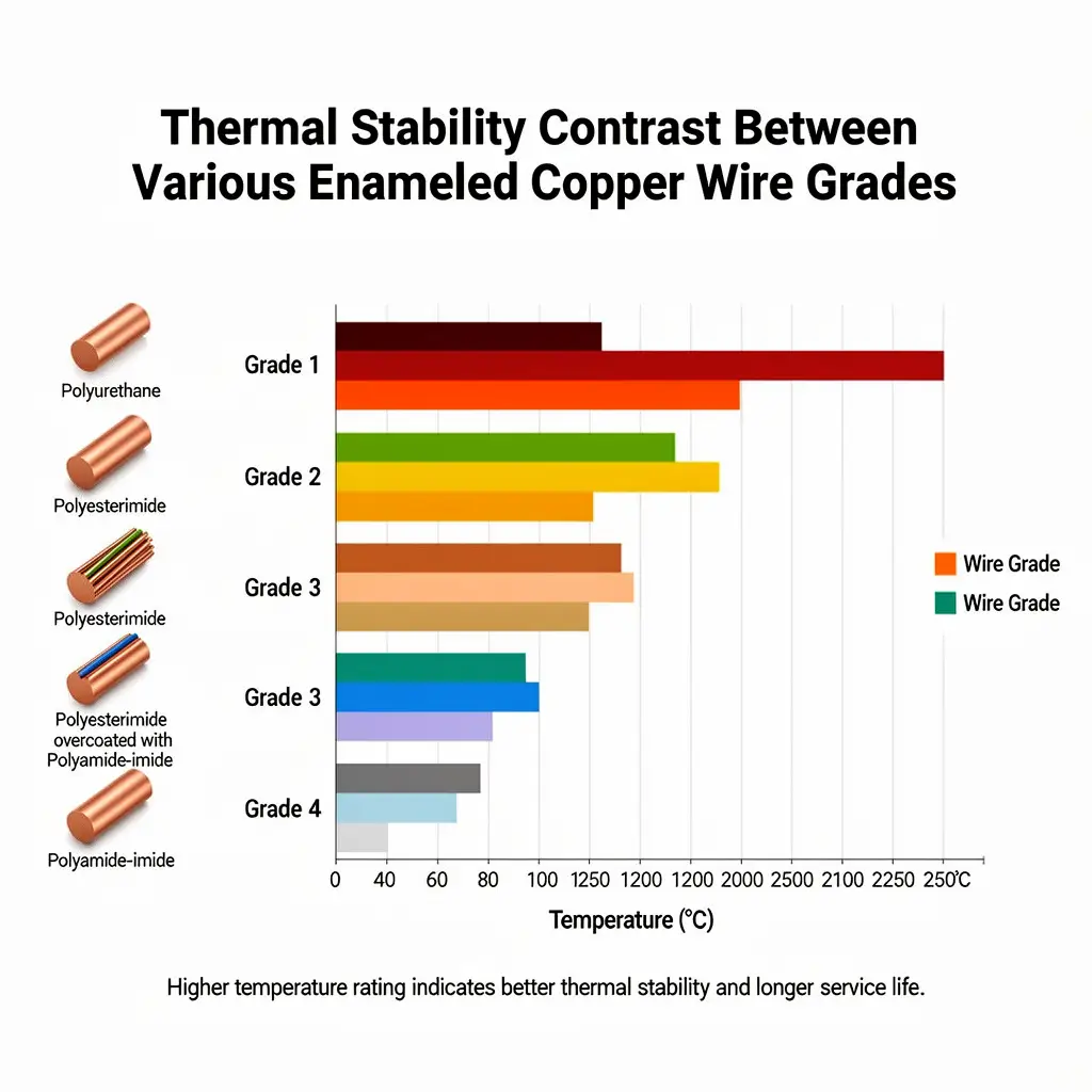
Core Definition and Evaluation Dimensions of Enameled Wire Thermal Stability
What Is Thermal Stability of Enameled Wire?
Thermal stability of enameled wire refers to the ability of the enamel insulation film to retain its mechanical, electrical, and chemical properties under controlled elevated temperature conditions. Thermal stability is inherently a time–temperature coupled property—identical enamel exhibits markedly different stability at different temperatures. Common evaluation dimensions include:
- Short-term overload capability (maintaining ≥50% of initial breakdown voltage after 1,000 h at Tp + 80°C)
- Long-term thermal life (temperature corresponding to 20,000 h lifetime = temperature index TI)
- Thermal shock resistance (no cracking upon rapid cooling from elevated temperature)
- Softening breakdown temperature (critical temperature at which breakdown voltage drops sharply)
- Arrhenius activation energy (Ea) (energy barrier for thermal degradation reactions)
- Glass transition temperature (Tg) (critical temperature at which enamel transitions from glassy to rubbery state)
- Weight loss rate (volatiles loss at elevated temperature)
- Breakdown voltage retention ratio (ratio of post-aged to pre-aged breakdown voltage)
- Dielectric loss factor (tanδ) (dielectric loss at elevated temperature)
Failure Modes of Thermal Aging
Failure modes of enamel films during thermal aging include:
- Polymer degradation: main-chain scission, side-chain cleavage
- Thermo-oxidative degradation: oxygen-involved chain reaction degradation
- Hydrolytic degradation: moisture-involved chemical degradation
- Plasticizer/volatile loss: embrittlement of enamel film
- Crosslink density change: embrittlement or softening of enamel film
- Pinholes and cracking: loss of enamel film continuity
- Breakdown voltage decline: loss of insulating functionality
- Adhesion loss: enamel delamination
Overview of Enameled Wire Temperature Class System
Per IEC 60085 and UL 1446, enameled wire temperature classes are defined as follows:
| Class Designation | Temperature Index (TI) (°C) | Typical Enamel System | Typical Applications |
|---|---|---|---|
| Y | 90 | Cotton/paper/unimpregnated | Legacy transformers |
| A | 105 | Oil-based resins, oil-impregnated paper | Legacy motors |
| E | 120 | Polyurethane resins, epoxy | Early-generation enameled wire |
| B | 130 | PVF/PEW + impregnating varnish | General-purpose motors, household appliances |
| F | 155 | Modified PEW/UEW + impregnating varnish | General-purpose motors, transformers |
| H | 180 | PEI/EIW + silicone organic impregnating varnish | High-temperature motors, transformers |
| N | 200 | Modified PEI/PAI | High-temperature motors |
| R | 220 | PAI/polyamide-imide | Traction motors, aerospace |
| C | ≥240 | PI (polyimide) | Aerospace, defense, ultra-high-temperature applications |
Standardized Test Systems
- IEC 60085: Electrical insulation – Thermal evaluation and designation
- IEC 60851-1: Winding wires – Test methods – Part 1: General requirements
- IEC 60851-4: Chemical properties
- IEC 60851-5: Electrical properties (breakdown voltage)
- IEC 60851-6: Thermal properties (thermal shock, softening breakdown, weight loss)
- ASTM D2307: Thermal endurance of film-insulated magnetic round steel wire
- GB/T 4074 / GB 4074.25: Chinese national standards
- UL 1446: North American insulation system certification
- NEMA MW 1000 Part 3: Thermal life
- JIS C 3202 / C 3003: Japanese Industrial Standards
- ISO 21678: Long-term thermal aging of polymers
Enamel Chemical Systems by Temperature Class
The fundamental thermal stability differences among temperature classes arise directly from their distinct enamel chemical systems.
Class B (130°C): Polyester / Polyvinyl Formal (PVF)
Chemical Structure:
– Polyvinyl formal (PVF)
– Polyester (PE)
– Single-layer coating
Key Parameters:
– Tg: 70–85°C
– Softening breakdown temperature: 155–170°C
– Thermal shock temperature: 130°C
– Weight loss (200°C/24 h): ≤2%
– Activation energy (Ea): 80–90 kJ/mol
Advantages and Disadvantages:
– ✅ Lowest cost (typical 50–80 RMB/kg)
– ✅ Easy processability, flexible film
– ❌ Moderate thermal stability
– ❌ Rapid breakdown voltage decay
– ❌ Suitable only for Class B applications
Class F (155°C): Modified Polyester / Modified Polyurethane
Chemical Structure:
– Modified polyester (Modified PE, terephthalate + modified monomers)
– Modified polyurethane (Modified UEW)
– Single- or double-layer coating
Key Parameters:
– Tg: 110–130°C
– Softening breakdown temperature: 200–220°C
– Thermal shock temperature: 155–175°C
– Weight loss (200°C/24 h): ≤1.5%
– Activation energy (Ea): 90–100 kJ/mol
Advantages and Disadvantages:
– ✅ Class F represents the industrial standard, offering optimal cost–performance balance
– ✅ High film tensile strength
– ✅ Excellent solderability (UEW)
– ❌ Accelerated enamel degradation at elevated temperatures
– ❌ Not suitable for continuous full-load operation at 155°C
Class H (180°C): Polyester-Imide (PEI) / Modified PEI
Chemical Structure:
– Polyester-imide (PEI/EIW)
– Condensation polymer of terephthalic acid + diol + diamine/imide compound
– Typically dual-layer (primer + topcoat)
Key Parameters:
– Tg: 150–180°C
– Softening breakdown temperature: 240–260°C
– Thermal shock temperature: 180–200°C
– Weight loss (200°C/24 h): ≤1%
– Activation energy (Ea): 100–115 kJ/mol
Advantages and Disadvantages:
– ✅ Outstanding comprehensive performance
– ✅ Suitable for continuous long-term operation at Class H (180°C)
– ✅ High mechanical strength
– ✅ Excellent chemical and moisture resistance
– ❌ 30–50% higher cost than Class F
– ❌ Higher enamel film hardness
Class N (200°C): Modified PEI / Polyamide-Imide (PAI)
Chemical Structure:
– Modified polyester-imide (Modified PEI)
– Polyamide-imide (PAI)
– Higher aromatic content
Key Parameters:
- Tg: 200–230 °C
- Softening-breakdown temperature: 280–300 °C
- Thermal shock temperature: 200–220 °C
- Weight loss (220 °C/24 h): ≤0.8 %
- Activation energy Ea: 115–130 kJ/mol
Advantages and Disadvantages:
- ✅ Long-term stable operation at 200 °C
- ✅ Excellent radiation resistance and chemical resistance
- ❌ Higher cost (20–40 % more than Class H)
- ❌ Narrowenamel film processing window
Class R (220 °C): Polyamide-imide (PAI)
Chemical Structure:
- Polyamide-imide (PAI)
- Condensation polymerization of trimellitic anhydride + diamine
- Single- or double-layer coating
Key Parameters:
- Tg: 250–280 °C
- Softening-breakdown temperature: 320–350 °C
- Thermal shock temperature: 220–240 °C
- Weight loss (220 °C/24 h): ≤0.5 %
- Activation energy Ea: 130–150 kJ/mol
Advantages and Disadvantages:
- ✅ Long-term operation at 220 °C
- ✅ Suitable for traction motors and wind power generators
- ✅ Vibration- and impact-resistant
- ❌ High cost (CNY 120–200/kg)
- ❌ Difficultenamel film processing
Class C (240 °C+): Polyimide (PI)
Chemical Structure:
- Polyimide (PI)
- Condensation polymerization of pyromellitic dianhydride + diamine
- Typically two-layer structure: primer (PEI/PE) + topcoat (PI)
Key Parameters:
- Tg: 300–400 °C
- Softening-breakdown temperature: 380–450 °C
- Thermal shock temperature: 240–300 °C
- Weight loss (240 °C/24 h): ≤0.5 %
- Activation energy Ea: 140–180 kJ/mol
Advantages and Disadvantages:
- ✅ Top-tier thermal stability (240–300 °C)
- ✅ Suitable for aerospace and defense applications
- ✅ Radiation-resistant and resistant to extreme environments
- ❌ Highest cost (CNY 200–400/kg)
- ❌ Highenamel film hardness and narrow processing window
- ❌ Poor adhesion to copper (requires primer)
Comparative Analysis of Key Thermal Stability Parameters Across Classes
This section constitutes the core of the document, presenting thermal stability differences across classes via a comprehensive table and multiple focused comparisons.
Primary Comparison Table: Eight Key Thermal Stability Parameters
| Class | TI (°C) | enamel Film Chemistry | Tg (°C) | Softening-Breakdown (°C) | Thermal Shock (°C) | Weight Loss at 200 °C/24 h | Dielectric Breakdown Voltage Retention at 180 °C/1000 h | Ea (kJ/mol) |
|---|---|---|---|---|---|---|---|---|
| B | 130 | PVF/PEW | 70–85 | 155–170 | 130 | ≤2 % | 30–50 % (not usable) | 80–90 |
| F | 155 | Modified PEW/UEW | 110–130 | 200–220 | 155–175 | ≤1.5 % | 50–70 % | 90–100 |
| H | 180 | PEI/EIW | 150–180 | 240–260 | 180–200 | ≤1 % | 75–85 % | 100–115 |
| N | 200 | Modified PEI/PAI | 200–230 | 280–300 | 200–220 | ≤0.8 % | 80–90 % | 115–130 |
| R | 220 | PAI | 250–280 | 320–350 | 220–240 | ≤0.5 % | 85–95 % | 130–150 |
| C | 240+ | PI | 300–400 | 380–450 | 240–300 | ≤0.5 % | 90–99 % | 140–180 |
Interpretation of Comparisons:
- Temperature Index (TI): Increases by 110 °C from Class B to Class C, representing an 85 % span
- Glass Transition Temperature (Tg): Increases by 230–315 °C from Class B to Class C, representing >400 % span
- Softening-breakdown temperature: Increases by 225–280 °C from Class B to Class C
- Thermal shock temperature: Increases by 110–170 °C from Class B to Class C
- Weight loss rate: Decreases by 75–87 % (substantially reduced volatiles at elevated temperatures) from Class B to Class C
- Dielectric breakdown voltage retention: Improves by 60–69 percentage points from Class B to Class C
- Activation energy (Ea): Increases by 60–100 kJ/mol from Class B to Class C
Key Findings
- Large temperature span: Each class increment (25–30 °C) improves key parameters by 50–100 %
- Non-linear improvement: B→F yields ~2× improvement; H→C yields ~50 % improvement
- PI far exceeds others: Class C PI leads comprehensively across all parameters
- PAI approaches PI: Class R PAI performance closely matches Class C in the 200–220 °C range
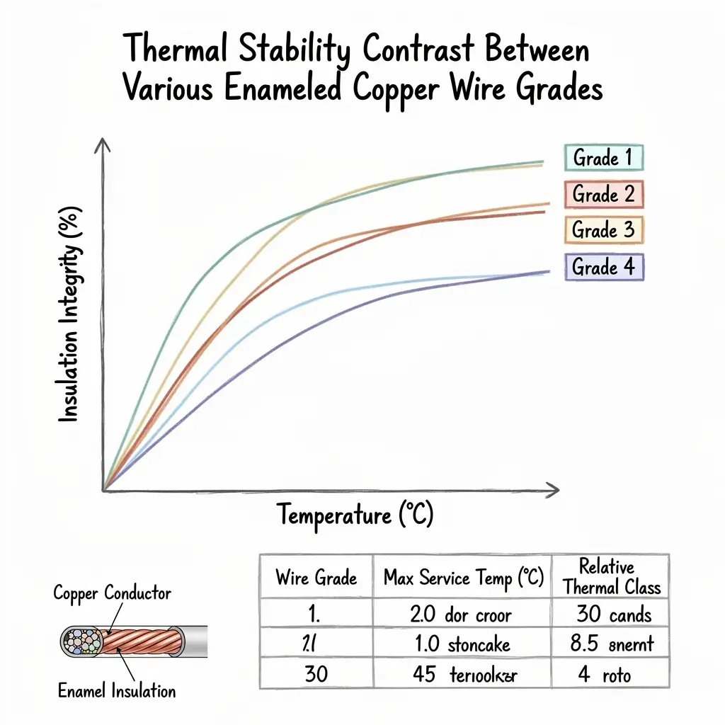
Comparative Analysis of Short-Term Overload Capability Across Classes
Short-term overload testing (Tp + 80 °C) evaluates enameled copper wire “overload lifetime” under transient ultra-high temperature and voltage conditions.
Test Conditions
- Test temperature = Tp + 80 °C (where Tp is the temperature index of the class)
- Test voltage: 1.5–2.5× rated AC voltage, 50 Hz
- Specimen: 1.000 mm round copper enameled wire, Grade 2, twisted
- Failure criterion: breakdown at 5 mA leakage current
- Target: ≥1000 h for 5 specimens
Test Temperatures and Representative Results by Class
| Class | Tp (°C) | Test Temperature (Tp+80 °C) | 1000 h Breakdown Rate | Notes |
|---|---|---|---|---|
| B | 130 | 250 °C | 60–80 % | e.g., 2 out of 5 specimens may fail |
| F | 155 | 250 °C | 80–95 % | Majority pass |
| H | 180 | 260 °C | 90–99 % | Nearly all pass |
| N | 200 | 280 °C | 95–99 % | Excellent |
| R | 220 | 300 °C | ≥99 % | Outstanding |
| C | 240 | 320 °C | ≥99 % | Outstanding |
Comparative Short-Term Overload Curves
Assuming Class H PEI exhibits 90 % breakdown rate at 260 °C/1000 h (baseline):
- Class B PVF at 250 °C/1000 h: ~50–60 %
- Class F modified PE at 250 °C/1000 h: ~80 %
- Class H PEI at 260 °C/1000 h: ~90 %
- Class N modified PEI at 280 °C/1000 h: ~95 %
- Class R PAI at 300 °C/1000 h: ~99 %
- Class C PI at 320 °C/1000 h: ~99 %
Comparison Trends:
- Higher class → stronger short-term overload capability
- Each class increment improves overload capability by ~10–20 %
- Class B fails readily at 250 °C under short-term exposure
- Class C PI remains stable even at 320 °C
Chemical Mechanism of Short-Term Overload
Under short-term overload,enamel film undergoes:
- Polymer chain scission (main-chain C–C bond cleavage)
- Thermo-oxidation (C–H bond cleavage generating free radicals)
- enamel film softening (exceeding Tg, increased molecular chain mobility)
- Adhesion loss (failure atenamel film–copper interface)
- Reduced dielectric breakdown voltage (decreased insulation resistance)
PI (polyimide), owing to its aromatic rigid backbone and imide ring structure, requires exceptionally high energy for main-chain scission under transient ultra-high temperature, thus delivering the strongest short-term overload capability.
Comparative Analysis of Long-Term Thermal Life Across Classes
Long-term thermal life is determined per ASTM D2307 using multi-temperature-point Arrhenius extrapolation to establish Temperature Index (TI).
Arrhenius Extrapolation Principle
Assumingenamel film thermal aging follows first-order reaction kinetics:
ln(L) = A + B / T
Where:
- L: failure lifetime (h)
- T: thermodynamic temperature (K)
- A: material-dependent constant
- B = Ea / R (slope)
- Ea: activation energy (kJ/mol)
- R: gas constant, 8.314 J/(mol·K)
Arrhenius Parameters by Class
| Class | Enamel Chemistry | Ea (kJ/mol) | B Value (Calculated) | Applicable Temperature Range |
|---|---|---|---|---|
| B | PVF/PEW | 80–90 | 9620–10820 | 130–180°C |
| F | Modified PE/UEW | 90–100 | 10820–12030 | 155–220°C |
| H | PEI/EIW | 100–115 | 12030–13830 | 180–260°C |
| N | Modified PEI/PAI | 115–130 | 13830–15630 | 200–300°C |
| R | PAI | 130–150 | 15630–18040 | 220–340°C |
| C | PI | 140–180 | 16830–21650 | 240–380°C |
Temperature–Lifetime Relationship Comparison Across Classes
Assuming a baseline lifetime of 20,000 h at each class’s Temperature Index (Tp), calculated using the Arrhenius model:
Class H (TI = 180°C) Arrhenius Model:
– 170°C: ~40,000 h
– 180°C: 20,000 h
– 190°C: ~10,000 h
– 200°C: ~5,000 h
– 220°C: ~1,200 h
Class F (TI = 155°C) Arrhenius Model:
– 145°C: ~40,000 h
– 155°C: 20,000 h
– 165°C: ~10,000 h
– 175°C: ~5,000 h
– 195°C: ~1,200 h
Class C (TI = 240°C) Arrhenius Model:
– 230°C: ~40,000 h
– 240°C: 20,000 h
– 250°C: ~10,000 h
– 260°C: ~5,000 h
– 280°C: ~1,200 h
Validation of the 8–10 K Rule
Per the 10 K rule, lifetime halves with every 10 K temperature increase:
– Class H: 180°C → 20,000 h; 190°C → ~10,000 h; 200°C → ~5,000 h ✅
– Class PI: 240°C → 20,000 h; 250°C → ~10,000 h; 260°C → ~5,000 h ✅
Lifetime Comparison Across Classes at Identical Operating Temperature
At 180°C operating temperature:
| Class | TI (°C) | Predicted Lifetime at 180°C |
|---|---|---|
| B | 130 | Not applicable (exceeds TI by 50°C; instantaneous degradation) |
| F | 155 | Not applicable (exceeds TI by 25°C; severe aging) |
| H | 180 | 20,000 h (design lifetime) |
| N | 200 | ~60,000 h (3× lifetime) |
| R | 220 | ~200,000 h (10× lifetime) |
| C | 240 | ~500,000 h (25× lifetime) |
Comparison Trend:
– At 180°C, Class H represents the baseline configuration.
– Upgrading to Class N increases lifetime by 3×.
– Upgrading to Class C increases lifetime by 25×.
Lifetime Comparison Across Classes at Identical Lifetime Target
At 20,000 h lifetime:
| Class | Temperature Corresponding to 20,000 h Lifetime |
|---|---|
| B | 130°C |
| F | 155°C |
| H | 180°C |
| N | 200°C |
| R | 220°C |
| C | 240°C |
Comparison Trend:
– Total span from Class B to Class C: 110°C.
– Each class upgrade increases temperature capability by 25–30°C.
Comparative Breakdown of Dielectric Breakdown Voltage Retention Across Classes
Dielectric breakdown voltage retention is the core metric for evaluating enamel film electrical insulation lifetime.
Test Methodology
- Aging temperature: Tp + 30°C (accelerated aging) per class
- Aging durations: 0, 500, 1000, 2000, and 5000 h
- Test method: Twisted-wire breakdown voltage test
- Evaluation criterion: (Breakdown voltage after aging / Breakdown voltage before aging) × 100%
Comparative Breakdown Voltage Retention Curves Across Classes
Baseline Breakdown Voltage (at 0 h): 10–15 kV (1.000 mm enameled round copper wire)
| Class | Aging Temperature | 500 h | 1000 h | 2000 h | 5000 h |
|---|---|---|---|---|---|
| B | 160°C | 80% | 60% | 40% | 20% |
| F | 185°C | 90% | 75% | 55% | 30% |
| H | 210°C | 95% | 88% | 78% | 65% |
| N | 230°C | 97% | 92% | 85% | 75% |
| R | 250°C | 99% | 95% | 90% | 82% |
| C | 270°C | 99% | 97% | 95% | 90% |
Comparison Trend:
– Higher classes exhibit slower decay in breakdown voltage retention.
– Class B retains only 20% after 5000 h (failure).
– Class C retains 90% after 5000 h (stable).
– Class H retains 65% after 5000 h (acceptable).
Failure Criterion Comparison
Failure defined as breakdown voltage retention dropping to 50%:
– Class B: ~2000 h to failure
– Class F: ~3000 h to failure
– Class H: ~6000 h to failure
– Class N: ~10,000 h to failure
– Class R: ~15,000 h to failure
– Class C: ~20,000 h to failure
Comparative Thermal Shock Performance Across Classes
Thermal shock testing evaluates enamel film resistance to cracking under short-term overtemperature exposure followed by rapid cooling.
Test Method (IEC 60851-6, Test 9)
- Specimen: Enameled round copper wire
- Heating: Oven, 30 min (per class thermal shock temperature)
- Cooling: Ambient temperature
- Wrapping: 5–10 turns on 1× mandrel
- Crack inspection: Magnifying lens
Comparative Thermal Shock Temperatures Across Classes
| Class | Standard Thermal Shock Temperature | Test Result | Remarks |
|---|---|---|---|
| B | 130°C | 5/5 Pass | Marginal |
| F | 155–175°C | 5/5 Pass | Good |
| H | 180–200°C | 5/5 Pass | Excellent |
| N | 200–220°C | 5/5 Pass | Excellent |
| R | 220–240°C | 5/5 Pass | Excellent |
| C | 240–300°C | 5/5 Pass | Outstanding |
Thermal Shock Chemical Mechanism
Failure modes:
– Internal stress in enamel film: Mismatch between coefficient of thermal expansion (CTE) of copper and enamel
– Interfacial cracking: Loss of adhesion
– Enamel embrittlement: Transition to glassy state resulting in brittleness
PI exhibits optimal thermal shock performance due to its superior CTE match with copper (PI ~30 ppm/°C; Cu ~17 ppm/°C).
Comparative Dielectric Loss and Insulation Performance Across Classes
Dielectric loss tangent (tanδ) quantifies dielectric power loss of the enamel film under alternating electric fields.
Test Methodology
- Frequency: 50 Hz or 1 kHz
- Temperature range: Ambient to 200°C (class-dependent)
- Electrode configuration: Twisted-wire electrode
Comparative tanδ Values Across Classes (at 50 Hz)
| Class | tanδ at Ambient | tanδ at 100°C | tanδ at 150°C | tanδ at 200°C |
|---|---|---|---|---|
| B | 0.005 | 0.015 | 0.030 | 0.080 |
| F | 0.005 | 0.010 | 0.020 | 0.040 |
| H | 0.005 | 0.008 | 0.012 | 0.020 |
| N | 0.004 | 0.006 | 0.010 | 0.015 |
| R | 0.004 | 0.005 | 0.008 | 0.012 |
| C | 0.003 | 0.004 | 0.006 | 0.008 |
Comparison Rules:
- The higher the thermal class, the lower the tanδ and the smaller its variation with temperature.
- Class B exhibits tanδ = 0.080 at 200°C (severe dielectric loss).
- Class C polyimide (PI) maintains tanδ < 0.01 across the full temperature range (exceptional performance).
PDIV (Partial Discharge Inception Voltage) Comparison
| Class | PDIV at Room Temperature | PDIV at Elevated Temperature (Tp) |
|---|---|---|
| B | 800 V | 400 V |
| F | 900 V | 550 V |
| H | 1000 V | 750 V |
| N | 1100 V | 900 V |
| R | 1200 V | 1050 V |
| C | 1300 V | 1200 V |
Comparison Rules:
- PI exhibits nearly constant PDIV at elevated temperatures (excellent corona resistance).
- Class B PDIV halves at elevated temperatures (significant degradation).
Cost Comparison Across Thermal Classes
Cost is a practical constraint in thermal class selection.
Unit Price Reference (China Market, 2026)
| Class | Unit Price for 1.000 mm Wire | Cost Multiplier (B = 1.0) |
|---|---|---|
| B | ¥50–¥80/kg | 1.0 |
| F | ¥60–¥100/kg | 1.2–1.5 |
| H | ¥80–¥150/kg | 1.6–2.5 |
| N | ¥120–¥180/kg | 2.0–3.0 |
| R | ¥150–¥250/kg | 2.5–4.0 |
| C | ¥200–¥400/kg | 3.0–6.0 |
Cost-Performance Analysis
- B → F: Cost increases by 30–50%, thermal stability improves by 50% — high cost-performance ratio.
- F → H: Cost increases by 40–60%, thermal stability improves by 30% — reasonable cost-performance ratio.
- H → N: Cost increases by 30–50%, thermal stability improves by 15% — premium pricing.
- N → R: Cost increases by 30–40%, thermal stability improves by 12% — high premium.
- R → C: Cost increases by 50–100%, thermal stability improves by 10% — highest premium.
Optimal Cost-Based Selection Principles
- Avoid over-specification: Select Class H if sufficient; do not select Class N unnecessarily.
- Avoid under-specification: Class B must not be used in environments exceeding 155°C.
- Consider failure cost: Recall costs far exceed the price differential of magnet wire.
- Consider lifecycle cost: Higher thermal classes may reduce total lifecycle cost.

Typical Application Scenarios by Thermal Class
| Application | Operating Temperature | Recommended Class | Recommended Enamel Chemistry |
|---|---|---|---|
| Small household appliances (e.g., electric fans, blenders) | 90–110°C | B/F | PEW |
| Medium-sized motors (e.g., washing machines, air conditioners) | 120–140°C | F | Modified PEW |
| General-purpose power transformers | 105–130°C | B/F | PEW |
| High-efficiency motors (IE3/IE4) | 130–150°C | F/H | PEI |
| Traction motors for new-energy vehicles | 140–160°C | H/N | PEI/modified PEI |
| Railway traction motors | 155–180°C | H/N | PEI/PAI |
| Wind turbine generators | 130–160°C | H/N | PEI/PAI |
| Dry-type distribution transformers | 130–155°C | F/H | PEI |
| High-frequency transformers (switch-mode power supplies) | 100–130°C | F/H | PEI/UEW |
| Aerospace motors | 180–220°C | R/C | PAI/PI |
| Military-special motors | 200–250°C | C | PI |
| Industrial induction coils for electric furnaces | 200–300°C | R/C | PAI/PI |
| Flue gas/exhaust treatment motors | 180–220°C | R | PAI |
| High-power fast-charging EV charging stations | 130–160°C | H/N | PEI |
Thermal Class Selection Decision Trees
Decision Tree 1: Selection Based on Operating Temperature
Operating Temperature Tp (°C)
├── T < 120°C: Y/A/E
├── 120 ≤ T < 140°C: B/F
├── 140 ≤ T < 160°C: F/H
├── 160 ≤ T < 180°C: H
├── 180 ≤ T < 200°C: N
├── 200 ≤ T < 220°C: R
└── T ≥ 220°C: C
Decision Tree 2: Selection Based on Expected Service Life
Expected Service Life L (years)
├── L < 5 years: Select TI = Tp
├── 5–10 years: Select TI = Tp + 10°C
├── 10–15 years: Select TI = Tp + 20°C
├── 15–20 years: Select TI = Tp + 30°C
└── > 20 years: Select TI = Tp + 40°C
Decision Tree 3: Selection Based on Safety Margin
Industry
├── General industrial: Select TI = Tp + 10°C
├── Automotive: Select TI = Tp + 20°C
├── Aerospace: Select TI = Tp + 30°C
├── Defense/military: Select TI = Tp + 40°C
└── Long-life equipment (e.g., transformers): Select TI = Tp + 30°C
Decision Tree 4: Selection Based on Transient Overload Frequency
Transient Overload Frequency
├── Rare (< 10 times/year): Select TI = Tp
├── Occasional (10–100 times/year): Select TI = Tp + 10°C
├── Frequent (100–1,000 times/year): Select TI = Tp + 20°C
└── Continuous overload: Select TI = Tp + 30°C
Common Selection Misconceptions
Misconception 1: “Higher Class Is Always Better”
Phenomenon: Blindly selecting Class C PI.
Problems:
– Cost inflated 3–5×.
– High enamel hardness narrows processability window.
– Poor adhesion between enamel and copper.
Best Practice: Select appropriately based on operating temperature plus safety margin.
Misconception 2: “Identical Class = Identical Performance”
Phenomenon: Assuming all Class H enamels deliver equivalent thermal stability.
Problems:
– Significant differences in enamel chemistry among manufacturers.
– Some Class H products are mislabeled modified Class F enamels.
– Third-party verification is essential.
Best Practice: Review third-party aging test reports.
Misconception 3: “Temperature Index (TI) Equals Maximum Operating Temperature”
Phenomenon: Misinterpreting TI as absolute upper operating limit.
Problems:
– TI denotes temperature at which 20,000-hour service life is achieved—not instantaneous maximum.
– Operating temperature should be 5–15°C below TI.
– Sustained operation at TI drastically reduces service life.
Best Practice: Set operating temperature = TI − 10–20°C.
Misconception 4: “Short-Term Performance Is Sufficient”
Phenomenon: Relying solely on breakdown voltage and thermal shock resistance.
Problems:
– Long-term thermal stability is the critical criterion.
– Short-term performance can be compensated; long-term degradation leads to irreversible failure.
Best Practice: Evaluate both short-term and long-term performance indicators holistically.
Misconception 5: “Thermal Shock Resistance Is Negligible”
Phenomenon: Ignoring thermal shock performance during selection.
Problems:
– Wide variation in thermal shock resistance across classes.
– Performance gap between Class B and Class C under thermal shock is extreme.
Best Practice: Verify both thermal shock temperature and duration specifications.
Summary
Significant differences exist in thermal stability among magnet wire thermal classes (B/F/H/N/R/C). This document systematically addresses: core definitions and evaluation dimensions of thermal stability (short-term overload capability, long-term service life, thermal shock resistance, softening breakdown, activation energy Ea, glass transition temperature Tg, weight loss, breakdown retention rate, tanδ, PDIV); enamel chemistry systems per class (PVF/PE/modified PE/UEW/PEI/PAI/PI); horizontal comparison of key thermal stability metrics across classes (primary comparative table: eight key parameters); short-term overload capability (breakdown rate after 1,000 h at Tp + 80°C); long-term thermal life (Arrhenius Ea, lifetime differences at identical temperature, temperature differences for identical lifetime); breakdown voltage retention rate (500–5,000 h); thermal shock performance (standard thermal shock temperature); dielectric loss and insulation performance (tanδ, PDIV); cost comparison (China market, 2026); typical application scenarios per class; selection decision trees (by temperature, service life, safety margin, overload frequency); and common selection misconceptions (class over-specification, equating class with performance, misinterpreting TI as operating limit, overemphasizing short-term metrics, neglecting thermal shock).
Core Comparison Rules:
- Wide temperature range: Temperature index increases from Class B to Class C by 110°C (85%).
- Activation energy difference: Ea increases from Class B to Class C by 60–100 kJ/mol.
- Lifetime difference: At identical operating temperatures, lifetime improves 25-fold from Class H to Class C.
- Cost difference: Cost increases 3–5 times from Class B to Class C.
- Application suitability: Class H is the industrial standard; Class C applies only to extreme scenarios.
Core selection principles:
- Operating temperature + safety margin = insulation class selection.
- For identical classes, compare enamel chemistry (PVF/PE/UEW/PEI/PAI/PI).
- Conduct integrated evaluation of short-term performance, long-term reliability, and cost-effectiveness.
- Validate aging data for critical applications.
- Avoid blindly pursuing higher insulation classes.
As emerging applications—including new-energy vehicles, wind power, photovoltaics, AI data centers, aerospace, and 5G/6G communications—impose increasingly stringent thermal stability requirements on magnet wire, insulation class selection is evolving toward “precision matching + optimized safety margin.” Engineers are advised to adopt a comprehensive decision framework: “application scenario → operating temperature → safety margin → insulation class selection → enamel chemistry → cost/performance balance,” systematically matching magnet wire specifications to actual operating conditions—including short-term overload, long-term life, thermal shock, thermal cycling, and thermal oxidation—to prevent both over-specification and under-specification.