


Introduction
Definition and Industrial Context of High-Temperature-Resistant Electrical Copper Foil
High-temperature-resistant electrical copper foil refers to copper foil products capable of maintaining excellent electrical conductivity, mechanical flexibility, insulation integrity, and oxidation resistance under long-term operating temperatures exceeding conventional upper limits. Conventional copper foil typically exhibits a long-term operating temperature range of 105°C to 130°C, corresponding to Class A or Class E electrical insulation systems; in contrast, high-temperature-resistant electrical copper foil must sustain reliable operation at elevated temperature classes—specifically Class F (155°C), Class H (180°C), Class N (200°C), or even Class R (220°C)—in demanding applications such as dry-type transformers, traction motors, locomotive traction transformers, wind and photovoltaic inverter reactors, battery module busbar interconnections, and electric vehicle (EV) drive motors. The high-temperature capability of copper foil is not determined solely by the melting point of the copper substrate, but rather results from the synergistic performance of the copper substrate, surface treatment layer, insulating coating, and composite insulation system.
Key Differentiators vs. Conventional Copper Foil
The critical distinctions between high-temperature-resistant electrical copper foil and conventional copper foil manifest across three dimensions. First, the copper substrate is typically fabricated from C1100 oxygen-free copper or C1020 high-purity copper, exhibiting a volume resistivity in the range of 1.71–1.73 μΩ·cm and an electrical conductivity of 100–101% IACS. Second, surface roughening employs fine-particle chemical roughening or corona treatment, achieving a surface roughness (Ra) of 0.5–2.5 μm to provide mechanical anchoring for subsequent coating adhesion. Third, the insulating coating utilizes high-temperature polymer systems—including polyimide (PI), polyetherimide (PEI), polytetrafluoroethylene (PTFE), modified epoxy resins, and impregnating varnishes—to ensure dielectric strength and bond strength retention under elevated-temperature conditions.
Scope and Target Audience of This Document
This document focuses exclusively on “high-temperature-resistant electrical copper foil,” systematically addressing its material systems, key performance parameters, failure modes under high-temperature exposure, manufacturing processes, representative application scenarios, selection criteria and engineering practices, as well as quality testing and reliability evaluation methodologies. It aims to provide a technically actionable framework for transformer design engineers, winding manufacturing engineers, new-energy-vehicle (NEV) electric drive system engineers, wind and photovoltaic inverter engineers, and procurement technical evaluators.
Material System of High-Temperature-Resistant Copper Foil
Copper Substrate Composition and Conductivity
The substrate material of high-temperature-resistant electrical copper foil is primarily oxygen-free copper C1100 and high-purity copper C1020. Copper content exceeds 99.95%, with oxygen content controlled below 30 ppm to prevent embrittlement and conductivity degradation caused by oxidation inclusions at elevated temperatures. The volume resistivity ranges from 1.71 μΩ·cm to 1.73 μΩ·cm, maintaining conductivity at 100% IACS to 101% IACS. Under continuous operation at 200°C, copper conductivity degradation does not exceed 6%. For higher-temperature applications, nickel-plated or tin-plated copper foil may be employed to retard oxidation.
Functional Differences of Surface Roughening Treatments
The two sides of copper foil are industrially designated as the matted side and the shiny side. The matted side features a micrometer-scale protrusion structure formed via chemical or corona roughening processes; its surface roughness (Ra) is typically controlled within 0.5 μm to 2.5 μm, providing mechanical anchoring points for insulating coatings and enhancing peel strength between the coating and copper foil. The shiny side retains the original rolled or electrodeposited smoothness, with Ra below 0.3 μm, and is primarily used for lamination bonding or electrical contact surfaces. High-temperature-resistant copper foil commonly employs either single-side or double-side roughening: single-side roughening is applied where copper foil bonds to an insulating layer, while double-side roughening is used in symmetrical structures requiring insulating coatings on both sides.
Coating Materials and Thermal Class Ratings
The insulating coating of high-temperature-resistant copper foil determines its thermal class rating. Common coating systems include polyimide (PI), rated for continuous use up to 240°C–260°C; polyetherimide (PEI), rated for 200°C–220°C; polytetrafluoroethylene (PTFE), rated for 250°C–260°C; modified epoxy, rated for 155°C–180°C; and impregnating varnish coatings, rated for 130°C–220°C depending on resin base. PI coatings are most widely applied across F-class, H-class, N-class, and R-class applications, exhibiting dielectric strength of 100 kV/mm to 200 kV/mm; although their coefficient of thermal expansion (CTE) differs significantly from that of copper, CTE mismatch can be substantially mitigated through elastomeric modification. PTFE coatings offer advantages in ultra-high-temperature and chemically corrosive environments but exhibit lower adhesion strength, necessitating compatibility with primer agents.
Oxidation Mechanisms and Protection Strategies for Copper Foil at Elevated Temperatures
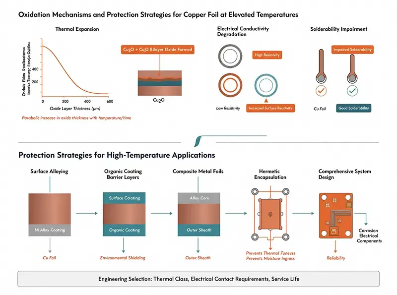
Copper undergoes significant oxidation in air above 200°C, forming a bilayer oxide film comprising Cu₂O and CuO; oxide film thickness increases parabolically with temperature and time. Oxidation elevates surface resistivity, degrades electrical contact performance, and impairs solderability. Protection strategies for high-temperature copper foil include surface alloying, organic coating barrier layers, composite metal foils, and hermetic encapsulation. Engineering selection among these protection strategies depends on thermal class requirements, electrical contact demands, and service life specifications.
Key Performance Parameters
Variation of Volume Resistivity and Conductivity with Temperature
The volume resistivity of copper increases linearly with rising temperature, conforming to the temperature coefficient of resistance (TCR) behavior typical of metallic conductors. At ambient temperature (20°C), copper exhibits a TCR of 0.00393 /°C, a volume resistivity of 1.71 μΩ·cm, and a conductivity of 100% IACS. At 100°C, 200°C, and 220°C, conductivity declines to approximately 74% IACS, 58% IACS, and 55% IACS, respectively. When selecting high-temperature-resistant copper foil, adequate margin must be reserved for conductivity degradation to prevent reduced current-carrying capacity under elevated temperatures.
Tensile Strength and Elongation
Tensile strength and elongation of copper foil exhibit pronounced temperature dependence. At ambient temperature, rolled annealed copper foil typically achieves tensile strength in the range of 400–500 MPa and elongation of 5–15%. At 100°C, tensile strength decreases to 350–420 MPa, while elongation increases to 8–18%. At 200°C, tensile strength further drops to 280–330 MPa, and elongation rises significantly to 15–30%, indicating marked material softening. For high-temperature windings, vibration environments, and short-circuit surge conditions, both parameters must be jointly evaluated to ensure mechanical reliability.
Thermal Compatibility Between Coating and Substrate
The coefficient of thermal expansion (CTE) of copper ranges from 16.5 ppm/°C to 17.0 ppm/°C, whereas polymer-based coatings typically exhibit CTE values between 30 ppm/°C and 80 ppm/°C—resulting in substantial mismatch. During thermal cycling, interfacial shear stress develops at the copper foil–coating interface, potentially causing coating delamination or microcracking. Polyimide (PI) coatings, when filled with inorganic fillers, achieve CTE values of 20–30 ppm/°C, reducing the CTE differential with copper foil to within 10 ppm/°C and thereby significantly enhancing interfacial stability. Polyetherimide (PEI) coatings exhibit CTE values of 40–50 ppm/°C—offering better thermal matching than PI but slightly lower dielectric strength.
Dielectric Strength and Dissipation Factor
The dielectric strength and dissipation factor (tanδ) of the insulating coating govern the electrical performance of the copper foil’s insulation layer. PI-coated foil delivers dielectric strength of 150–200 kV/mm and tanδ of 0.005–0.015 at ambient temperature; at 200°C, dielectric strength declines to 100–150 kV/mm and tanδ rises to 0.015–0.030. PEI-coated foil provides ambient-temperature dielectric strength of 80–120 kV/mm, with lower high-temperature degradation compared to PI. Polytetrafluoroethylene (PTFE)-coated foil offers ambient-temperature dielectric strength of 60–100 kV/mm and exceptionally low tanδ, exhibiting outstanding high-temperature stability but comparatively lower mechanical strength.
Thermal Class Rating and Temperature Index
Thermal class rating and Temperature Index (TI) constitute the core metrics for evaluating the long-term operating temperature capability of insulating materials. The four standard thermal classes—F-class (155°C), H-class (180°C), N-class (200°C), and R-class (220°C)—correspond to distinct high-temperature-resistant copper foil configurations. PI-coated copper foil achieves R-class (220°C) long-term operation; PEI-coated copper foil attains N-class (200°C) long-term operation; modified epoxy-coated copper foil is typically rated H-class (180°C); and impregnated varnish-coated copper foil may reach F-class to H-class depending on the resin base. Thermal class selection must align with the overall insulation system to prevent the copper foil from becoming the insulation bottleneck.
Failure Modes under High-Temperature Conditions
Copper Foil Surface Oxidation and Copper Ion Migration
Oxidation of copper foil and copper ion migration at elevated temperatures represent the most common failure modes. During long-term operation at 180°C to 220°C, a Cu₂O oxide layer forms on the copper foil surface, growing in thickness from an initial 0 μm to 0.5 μm–2 μm. This oxide layer reduces interfacial adhesion between the copper foil and the insulating coating, causing peel strength to degrade from an initial 5 N/cm–10 N/cm to 1 N/cm–3 N/cm. Under combined humid and electric field conditions, copper ions migrate through the insulation layer toward the cathode, forming dendritic conductive pathways. High-temperature-resistant copper foil mitigates oxidation and ion migration via surface alloying and organic coating shielding.
Coating Thermal Degradation and Embrittlement
Organic coatings undergo thermal degradation during prolonged high-temperature exposure, resulting in polymer chain scission, volatiles evolution, and deterioration of mechanical properties. Polyimide (PI) coatings exhibit elongation reduction from an initial 50% to below 10% after long-term operation at 240°C–260°C, manifesting pronounced embrittlement. Polyetherimide (PEI) coatings display a similar embrittlement trend at 200°C–220°C. Embrittlement induces microcracking in the coating under thermal cycling or mechanical stress, leading to a sharp decline in dielectric strength. For high-temperature-resistant copper foil, coating selection must avoid prolonged operation near the coating’s glass transition temperature (Tg) and thermal decomposition temperature (Td).
Interfacial Delamination and Microcracking under Thermal Cycling
Interfacial stress accumulation between copper foil and coating during thermal cycling constitutes another critical failure mode. During temperature cycling between –40°C and +180°C, the coefficient of thermal expansion (CTE) mismatch between copper foil and coating generates cyclic shear stress; after more than 200 cycles, interfacial microcracks and delamination initiate, ultimately progressing to large-area coating delamination and insulation failure.
CTE Mismatch among Copper Foil–Insulation Layer–Conductor
High-temperature-resistant copper foil is typically integrated with other insulation materials—such as enameled wire varnish films, glass fiber braided layers, or paper insulation layers—to form a composite insulation system. CTE mismatches among these constituent layers induce cumulative stress under thermal cycling; the CTE difference between copper foil and varnish film is particularly pronounced. Such CTE mismatch leads to interfacial delamination, copper foil lifting, and formation of insulation weak points. In complex winding configurations, failure risk arising from CTE mismatch is further heightened, necessitating mitigation through optimized material combinations and structural design.
Manufacturing Process
Rolled vs Electrodeposited Process Selection
High-temperature-resistant electrical copper foil is primarily manufactured via either the rolled or electrodeposited process. Rolled copper foil achieves a dense microstructure through repeated rolling and annealing, delivering superior conductivity and mechanical properties, with elongation ranging from 5% to 30%; however, it faces limitations on minimum achievable thickness and incurs higher production costs. Electrodeposited copper foil is produced via electroplating, offering lower cost and enabling thicknesses as low as 5 μm to 6 μm, yet exhibits inferior mechanical properties and elongation compared to rolled copper foil. For high-temperature electrical applications, rolled copper foil is preferred; electrodeposited copper foil may be selected where thickness requirements are < 35 μm or cost sensitivity is critical.
Surface Roughening and Chemical Treatment
Copper foil surface roughening techniques include chemical roughening, corona treatment, and mechanical sandblasting. Chemical roughening employs a dilute sulfuric acid–hydrogen peroxide mixture to generate micron-scale protrusions on the copper foil surface—this method is mature and cost-effective. Corona treatment utilizes high-frequency, high-voltage discharge to form micro-pores on the copper foil surface, achieving superior uniformity relative to chemical roughening. Mechanical sandblasting produces a controlled rough surface by high-velocity abrasive particle impingement; while roughness is adjustable, uniformity is comparatively poor. For high-temperature applications, chemical roughening or corona treatment is preferred.
Coating Process and Parameter Control
Insulating coating application methods include gravure coating, knife-over-roll coating, roll coating, and dip coating. Polyimide (PI) coatings are applied using polyamic acid precursor solutions, followed by imidization at 200°C to 350°C to form the final PI film. Polyetherimide (PEI) coatings are applied via solution coating and subsequently dried and cured at 150°C to 250°C. Polytetrafluoroethylene (PTFE) coatings are applied using dispersions and sintered at 350°C to 380°C. Critical coating parameters include solution viscosity, drying profile, imidization temperature, and coating thickness uniformity; parameter deviations directly impact dielectric strength and adhesion.
Enamel Coating and Impregnation
Enamel coating and impregnation constitute a key synergistic process between high-temperature-resistant copper foil and enameled wire. Enamel coating is applied via dip coating or roll coating, depositing high-temperature enamel onto the copper foil surface; subsequent baking and curing yield an enamel film 5 μm to 30 μm thick. Enamel-coated copper foil can be directly co-impregnated with enameled wire windings, forming an integrated three-layer composite insulation system: enamel film–copper foil–enameled wire. This process streamlines winding manufacturing and enhances insulation integrity, particularly suited for H-class, N-class dry-type transformers and high-temperature motor windings.
Typical Application Scenarios
High-Temperature Transformers (Dry-Type H-Class and Above) – Winding Termination and Lead Sections
In dry-type transformers operating continuously at H-class 180°C and N-class 200°C, the insulation at winding terminations and lead sections represents a weak link. High-temperature-resistant copper foil serves as termination insulation material, wrapped around winding ends and synergistically integrated with glass-fiber-covered magnet wire to form a unified insulation barrier. For H-class dry-type transformers, polyimide (PI)-coated copper foil (rated for 220°C) is employed; for N-class and R-class applications, either PI-coated or polytetrafluoroethylene (PTFE)-coated copper foil is used. Key advantages of high-temperature-resistant copper foil in termination insulation include minimal thickness, excellent bendability for wrapping, high dielectric strength, and compatibility with automated wrapping processes.
Traction Motors and Locomotive Traction Transformers
Traction motors and locomotive traction transformers operate continuously under H-class and N-class conditions while enduring high vibration levels and frequent start-stop cycles. In traction motors, high-temperature-resistant copper foil enhances insulation at winding terminations, slot openings, and lead-outs; in locomotive traction transformers operating continuously at H-class 180°C, such copper foil is applied for winding shielding and termination insulation under vibration and mechanical shock loads. Traction applications impose stricter requirements on copper foil—specifically regarding vibration resistance, impact resistance, and long-term thermal stability—than standard industrial motors.
New Energy Vehicle (NEV) Drive Motor Windings
NEV drive motors operate continuously at H-class 180°C and N-class 200°C, demanding exceptionally high performance from insulation materials in terms of temperature resistance, thermal conductivity, and mechanical robustness. High-temperature-resistant copper foil is applied in drive motors for winding termination insulation, phase-to-phase insulation, and pole coil insulation. The high-frequency switching inherent in drive motor operation places heightened demands on dielectric stability of insulation materials; PI-coated copper foil—characterized by low tanδ and high dielectric strength—has become the predominant choice.
Battery Module Busbars
Battery module busbars must conduct high currents and interconnect individual battery cells. Under battery thermal runaway or elevated-temperature conditions, conventional copper foil insulation coatings may fail. High-temperature-resistant copper foil—coated with either polyimide (PI) or polyetherimide (PEI)—provides insulation protection for module busbars, maintaining insulation integrity at temperatures ranging from 180°C to 200°C.
Wind Power and Photovoltaic Inverter Reactors
Wind power and photovoltaic inverter reactors operate continuously at F-class 155°C and H-class 180°C, imposing stringent requirements on insulation materials’ thermal endurance and thermal conductivity. High-temperature-resistant copper foil is utilized for reactor winding termination insulation, core shielding, and lead-out insulation. In high-power inverter applications, the electrical conductivity stability and dielectric stability of copper foil directly influence inverter efficiency and reliability.
Rail Transit Electromagnetic Shielding and Grounding
Rail transit systems mandate strict electromagnetic compatibility (EMC) and grounding reliability. High-temperature-resistant copper foil is deployed for shielding layers and grounding layers. In traction transformers and traction motors rated above H-class, shielding copper foil must retain both electrical conductivity and shielding effectiveness during continuous operation at temperatures ranging from 180°C to 200°C. Single-sided PI- or PEI-coated copper foil enables simultaneous maintenance of shielding conductivity and insulation protection.
Selection and Engineering Implementation
Thermal Class and Temperature Index Matching
Selection of high-temperature-resistant copper foil shall first be based on the thermal class of the insulation system. For F-class (155°C) systems, polyimide (PI), polyetherimide (PEI), or modified epoxy-coated copper foil may be selected; for H-class (180°C) systems, PI- or PEI-coated copper foil is preferred; for N-class (200°C) systems, PI-coated copper foil or PTFE-laminated copper foil is preferred; for R-class (220°C) systems, only PI- or PTFE-coated copper foil may be selected. Thermal class matching shall be based on the temperature index (TI) of each component within the insulation system to prevent the copper foil from becoming the weakest link in thermal endurance.
Engineering Considerations for Thickness Specifications
Common thickness specifications for high-temperature-resistant copper foil span multiple grades from 9 μm to 105 μm. Thin-gauge foils are suitable for flexible circuits and fine-insulation applications; medium-gauge foils are appropriate for general electrical winding end-turn insulation; thick-gauge foils are used for high-current busbars and electromagnetic shielding. Thickness selection shall comprehensively consider requirements for conductivity, dielectric strength, mechanical strength, and bendability. The minimum thickness for rolled-annealed copper foil is typically 35 μm, whereas electrodeposited copper foil can achieve a minimum thickness down to 9 μm.
Single-Sided vs. Double-Sided Coating Selection
Single-sided coated copper foil is suitable for applications requiring insulation on only one side of the foil—e.g., winding end-turn insulation or shield-layer insulation. The shiny side of single-sided coated foil may serve as the electrical contact surface or lamination bonding surface. Double-sided coated copper foil is employed where insulation is required on both sides—e.g., phase-to-phase insulation or module busbar insulation—offering higher dielectric strength but at increased cost. Selection shall be driven by the specific insulation structural requirements of the application.
Compatibility with Enamelled Wire and Glass-Fibre-Clad Wire
High-temperature-resistant copper foil is frequently integrated with enamelled wire and glass-fibre-clad wire to form composite insulation systems. In H-class and N-class dry-type transformers, the three-layer structure comprising glass-fibre-clad wire + high-temperature-resistant copper foil (for end-turns) + impregnating varnish represents the mainstream solution. In new-energy-vehicle traction motors, the configuration of enamelled wire + inter-phase high-temperature-resistant copper foil + impregnating varnish enables high power density and high reliability. Critical to co-design is parameter compatibility among layers—including coefficient of thermal expansion (CTE), temperature index (TI), and dielectric constant.
Standards and Certifications
Design and procurement of high-temperature-resistant electrical copper foil shall conform to relevant standards. IEC 60851 series standards specify test methods for winding wires and serve as reference for copper foil integration. IEC 60085 defines thermal classification of electrical insulation. GB/T 7672 specifies requirements for glass-fibre-clad wire. ASTM B272 defines chemical composition and mechanical property requirements for copper foil. UL 1446 specifies evaluation methods for thermal classification of electrical insulation systems. During procurement, request material data sheets, UL files, IEC test reports, and ISO 9001 certification from suppliers.
Quality Inspection and Reliability Assessment
Dielectric Breakdown Voltage Test
The dielectric breakdown voltage test is a core evaluation method for assessing the quality of copper foil insulation coatings. The test employs either parallel-plate electrodes or wound electrodes, with voltage gradually increased under standard atmospheric conditions until coating breakdown occurs; the breakdown voltage value is then recorded. For PI-coated copper foil, the dielectric breakdown voltage is typically required to be ≥ 5 kV (at 35 μm thickness); for PEI-coated copper foil, ≥ 3 kV; and for PTFE-coated copper foil, ≥ 2.5 kV. High-temperature testing shall be conducted at either 180°C or 200°C, with the breakdown voltage reduction not exceeding 30%.
Peel Strength Test
The peel strength test evaluates the adhesion between the copper foil substrate and its insulation coating. Testing is performed using either 90° or 180° peel methods, recording the force required per unit width to separate the layers. At ambient temperature, the peel strength of PI-coated copper foil is typically required to be ≥ 5 N/cm, while that of PEI-coated copper foil is ≥ 4 N/cm. High-temperature testing shall be conducted at 180°C, with the peel strength reduction not exceeding 50%.
Accelerated Thermal Aging Test
The accelerated thermal aging test subjects samples to prolonged exposure at temperatures above their rated operating temperature to establish an aging model and extrapolate service life at the rated temperature. Typically, three temperature levels are selected; multiple samples are placed at each temperature and key parameters measured periodically. Data analysis follows IEC 60216, employing Arrhenius regression to determine the Temperature Index (TI) and lifetime curve. This test constitutes the core methodology for lifetime assessment of high-temperature-resistant copper foil.
Thermal Shock and Thermal Cycling Test
The thermal shock and thermal cycling test evaluates the structural stability of copper foil under alternating temperature conditions. Test conditions typically range from –40°C to +180°C or –40°C to +200°C, with 200–1,000 cycles executed, each cycle holding for 30 minutes. Post-test inspection assesses coating delamination, lifting, cracking, and discoloration. Pass/fail criteria generally require no coating delamination, dielectric strength reduction < 20%, and peel strength reduction < 50%.
Copper Foil Surface Oxide Layer Thickness Measurement
Copper foil surface oxide layer thickness measurement evaluates the material’s oxidation resistance. Analytical methods include X-ray photoelectron spectroscopy (XPS), Auger electron spectroscopy (AES), X-ray diffraction (XRD), and cross-sectional scanning electron microscopy (SEM). In engineering practice, gravimetric analysis and four-point probe resistivity measurement are more commonly adopted. After long-term operation at 200°C, the oxide layer thickness shall be controlled within 1 μm; thickness exceeding 2 μm is considered significant oxidation.
Conclusions
High-temperature-resistant electrical copper foil is a core insulating material for high-temperature electrical applications, with its performance jointly determined by the copper substrate, surface roughening layer, insulating coating, and composite insulation system. The copper substrate is predominantly C1100 oxygen-free copper, maintaining conductivity at 100% IACS to 101% IACS; surface roughening employs either chemical or corona treatment, yielding a surface roughness (Ra) of 0.5 μm to 2.5 μm; insulating coatings are selected based on thermal class rating—polyimide (PI), polyetherimide (PEI), polytetrafluoroethylene (PTFE), modified epoxy, or impregnating varnish systems. The key engineering value of high-temperature-resistant copper foil lies in enabling long-term, reliable operation of high-temperature electrical systems rated from F-class through R-class, delivering dielectric strength of 150 kV/mm to 200 kV/mm (at ambient temperature, PI-coated) and peel strength exceeding 5 N/cm.