


Fiberglass covered wire (also known as fiberglass covered magnet wire, fiber glass insulated wire, FG wire, or glass wrapped wire) serves as a high-performance insulation upgrade over enameled wire (magnet wire). It consists of four structural components: a conductor (copper or aluminum), an optional underlying enamel coating, a glass fiber braid or serving layer, and an impregnating varnish. This product has become an irreplaceable electromagnetic material in demanding applications—including Class H rail traction motors, Class C dry-type transformers, marine propulsion motors, armored vehicle generators, wind turbine generators, induction heating coils, aerospace starter generators, rail transit traction converters, DC motors (including industrial spindle motors, elevator traction motors, and mine hoist motors), solenoids, relays, high-frequency inductors for SCR/SMPS, and power cable repair—where extreme conditions prevail: high temperature, severe vibration, high voltage, and aggressive chemical exposure.
Engineering selection of fiberglass covered wire is not merely a matter of matching thermal class ratings; rather, it constitutes a multi-variable engineering decision requiring comprehensive trade-offs among conductor material (copper/aluminum; round/flat), fiberglass type (E-glass, S-glass, D-glass, quartz fiber), braid density and layer count (GL1/GL2, Grade 1/2), impregnating varnish system (silicone, polyester, polyimide, epoxy), conductor cross-section (AWG/mm², CTE—coefficient of thermal expansion), mechanical processing requirements (slotting bend radius, winding tension, winding speed), environmental severity (chemical media, humidity cycling, radiation, oil immersion, vibration), regulatory compliance (NEMA MW 43–54, IEC 60317-33/46/61, GB/T 7672, UL 1446, IEEE 1776), failure modes (dielectric breakdown, thermal aging, mechanical cracking, moisture absorption and swelling), and total cost.
This document systematically addresses the fundamental principles for engineer-led fiberglass covered wire selection; the structural and materials science foundations; thermal class and lifetime engineering analysis; dielectric performance and voltage-scenario-based selection; mechanical performance and compatibility with slotting processes; environmental resistance and reliability; conductor material and geometric selection; industry-specific application decision matrices (motors, transformers, inductors, rail, aerospace, industrial, energy); comparative analysis versus alternative insulation systems (enameled wire, Kapton, paper-covered wire, mica tape); selection decision matrices and trade-off methodologies; supplier evaluation and quality assurance; and case studies with validation protocols—providing motor engineers, transformer engineers, aerospace engineers, rail transit engineers, OEM selection engineers, and procurement engineers with a systematic, actionable, and data-supported fiberglass covered wire selection decision framework.
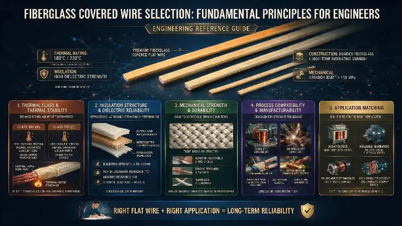
Fundamental Principles for Fiberglass Covered Wire Selection by Engineers
Selection of fiberglass covered wire differs fundamentally from standard enameled wire selection (“thermal class + enamel type”), exhibiting strong multidimensional engineering attributes, numerous constraints, and long-term impact.
Engineering Significance of Selection
The fiberglass covered wire selection decision directly affects:
- Equipment service life: Class H / Class C motors utilizing fiberglass covered wire achieve 10–20 years’ operational life
- Reliability: Insulation failure in traction motors may trigger pantograph-catenary accidents or fire
- Performance parameters: The fiberglass layer increases overall diameter by 30–80%, reducing slot fill factor by 5–15%
- Temperature rise limits: Fiberglass thermal class directly determines motor output capability (a 10 K rise halves service life)
- Cost structure: Fiberglass covered wire costs 2–5× more than equivalent enameled wire
- Manufacturability: The braid layer influences slotting process compatibility and equipment integration
Eight Core Inputs Required for Selection
A complete selection process requires prior determination of the following eight inputs:
- Operating temperature (Tp): Long-term hot-spot operating temperature (°C)
- Short-term overload temperature (Tpe): Transient overload or fault temperature
- Operating voltage (Vrms): Rated voltage and impulse voltage
- Frequency range: DC to 10 MHz
- Environmental severity: Chemical exposure, humidity, oil immersion, seawater, radiation
- Mechanical constraints: Bend radius, slotting tension, vibration amplitude
- Service life requirement: Typically 5–20 years
- Regulatory compliance: Industry-mandated standards and/or customer-specific requirements
Five Key Selection Outputs
Upon completion of selection, the following five items must be definitively specified:
- Conductor material and geometry (round/flat, copper/aluminum, wire diameter / cross-sectional area)
- Fiberglass type and braid layer count (GL1/GL2, Grade 1/2)
- Impregnating varnish system (silicone / polyester-imide / polyimide)
- Thermal class rating (Class 130/155/180/200/220/240)
- Supplier and quality grade (Grade A/B/C)
Structural and Materials Science Foundations of Fiberglass Covered Wire
Understanding the structural configuration and materials system of fiberglass covered wire forms the essential basis for correct selection.
Standard Construction
A typical fiberglass covered wire comprises four concentric layers (from innermost to outermost):
- Layer 1: Conductor: Round copper, flat copper, or aluminum (with optional plating)
- Layer 2: Underlying enamel coating (optional): Polyester, polyester-imide, or polyimide enamel
- Layer 3: Glass fiber braid or serving layer: Single-layer GL1 or double-layer GL2
- Layer 4: Impregnating varnish: Silicone, polyester, or polyester-imide
Conductor Layer
Material options:
- Oxygen-free copper (OFC, Cu ≥99.95%): Most widely used
- Tinned copper: Enhanced corrosion resistance and solderability
- Nickel-plated copper: Superior high-temperature and corrosion resistance
- Aluminum (Al, ≥99.5% purity): Used where weight sensitivity is critical (aerospace, rail)
- Copper-clad aluminum (CCA): Weight–cost optimization
Geometric options:
- Round conductor: General-purpose, compliant with AWG/metric standards
- Rectangular (flat) wire: Higher slot fill factor, primarily used in large motors
- Dual-strand or multi-strand stranded: For high-frequency and high-current applications
Wire gauge ranges:
- Round wire: 0.10 mm – 8.0 mm
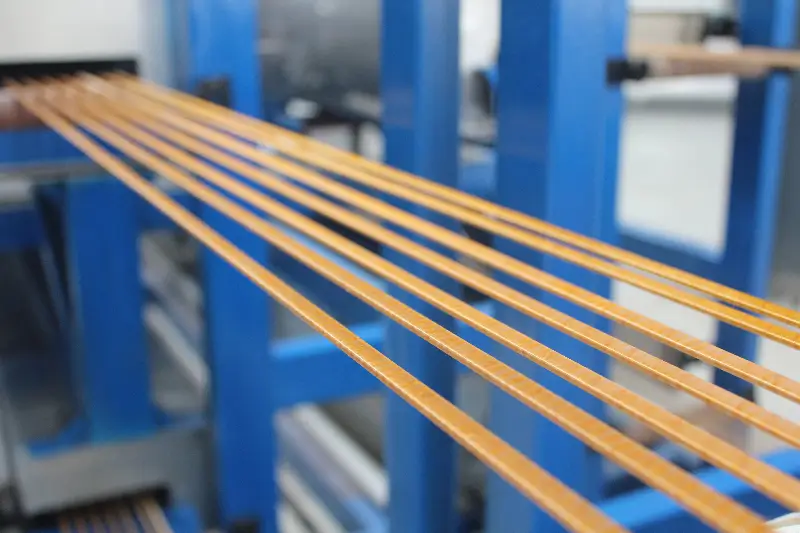
- Flat wire: Thickness 0.5–6.0 mm, width 2.0–25.0 mm
- Litz wire: 50–1000 strands, individual strand diameter 0.05–0.20 mm
Underlying Enamel Coating (Optional)
Some fiberglass covered wires incorporate an underlying enamel coating (Grade 2):
| Enamel | Thermal Class | Advantages | Limitations |
|---|---|---|---|
| Polyester (PEW) | Class 130/155 | Economical | Moderate thermal resistance |
| Polyester-imide (EIW) | Class 180 | Excellent thermal resistance and processability | Moderate cost |
| Polyamide-imide (AIW) | Class 200/220 | Exceptional thermal resistance and freon resistance | Higher cost |
| Polyimide (PIW) | Class 220/240 | Ultra-high thermal resistance | Poor processability |
Function of underlying enamel: Enhances turn-to-turn insulation integrity, reinforces primary insulation, and provides a smooth substrate facilitating uniform fiberglass braiding.
Fiberglass Layer (Primary Insulation)
Fiberglass types:
- E-glass (electrical-grade alkali-free glass): Most common, lowest cost
- S-glass (high-strength glass fiber): 30–50% higher tensile strength
- D-glass (dielectric glass): Low dielectric constant and low dielectric loss
- Quartz fiber (Quartz / SiO₂): Continuous use up to 1000 °C, for extreme-temperature applications
- High-silica glass fiber: Continuous use up to 1000 °C
Key E-glass parameters:
- Tensile strength: 1500–3500 MPa
- Continuous-use temperature: 400–550 °C
- Dielectric constant: 6.2–6.5 (at 1 MHz)
- Dissipation factor (tan δ): 0.002–0.005 (at 1 MHz)
- Elongation at break: 3–5%
- Filament diameter: 5–13 μm
Braiding methods:
- Braid: Diamond-pattern interlacing, density 60–95%, controllable coverage
- Serve/Spiral: Unidirectional or crossed, uniform density
- Advantage of serving: Suitable for large-diameter conductors and high-angle winding
Braid coverage (density):
- GL1 single-layer: ~75–85% coverage
- GL2 double-layer: ~90–95% coverage
- High-coverage: 95–98% (for elevated dielectric-class requirements)
Outer diameter increase attributable to braid layer:
- GL1 single-layer: ~0.10–0.30 mm (round wire)
- GL2 double-layer: ~0.20–0.50 mm
- Increase is significantly greater for flat wire
Impregnating Varnish Layer
Silicone:
- Thermal Class: 200–220
- Characteristics: Heat-resistant, ozone-resistant, corona-resistant
- Limitations: Moderate mechanical strength
- Applications: Class H motors, aerospace motors
Polyester (PE):
- Thermal Class: 155–180
- Characteristics: Cost-effective, easy to impregnate
- Applications: General-purpose motors
Polyester-imide (PEI):
- Thermal Class: 180–200
- Characteristics: Heat-resistant, excellent mechanical strength
- Applications: Traction motors, dry-type transformers
Epoxy:
- Thermal Class: 130–155
- Characteristics: High adhesion strength, chemical resistance
- Applications: Electrical equipment, coil bonding
Polyimide (PI):
- Thermal Class: 220–240
- Characteristics: Extremely high heat resistance, radiation resistance
- Applications: Aerospace, nuclear power, defense
Comprehensive Material System Selection
| Thermal Class | Conductor | Glass Fiber | Impregnating Varnish | Application |
|---|---|---|---|---|
| Class 130 | Cu | E-glass | Epoxy | General electrical appliances |
| Class 155 | Cu | E-glass | Polyester | General-purpose motors |
| Class 180 | Cu | E-glass | Polyester-imide | Standard motors |
| Class 200 | Cu | E-glass | Silicone | Class H motors, traction applications |
| Class 220 | Cu/Ni | S-glass | Silicone | High-temperature motors, aerospace |
| Class 240 | Cu/Ni | Quartz | Polyimide | Defense, nuclear power |
Thermal Class and Thermal Life Analysis
Thermal class is the primary selection criterion for glass-fiber-covered magnet wire, determining the ultimate service life of the motor.
Thermal Class Definition
Thermal class is defined based on the continuous operating life of 20,000 hours for the insulation system at a specified temperature (per industry-standard Arrhenius accelerated aging principle):
| Class (IEC 60085) | Operating Temperature (°C) | Class (UL 1446) |
|---|---|---|
| Class Y | 90 | Class Y |
| Class A | 105 | Class A |
| Class E | 120 | Class E |
| Class B | 130 | Class B |
| Class F | 155 | Class F |
| Class H | 180 | Class H |
| Class N | 200 | Class N |
| Class R | 220 | Class R |
| Class 250 | 250 | Class 250 |
| Class C | >220 | Class C |
Arrhenius Thermal Life Equation
The relationship between life and temperature follows the Arrhenius equation:
- ln(L) = A + B / T
- Empirical rule: Life halves for every 10°C increase in temperature
- 8°C increase → life reduced to ½ (industry-simplified “10K rule”)
Application Examples:
- Class H (180°C): Standard life = 20,000 h (~2.3 years continuous operation)
- Actual Class H operation at 160°C: Life extended by 4× (>10 years)
- Actual Class H operation at 200°C: Life halved (1 year)
- Actual Class H operation at 220°C: Life reduced to 1/8 (~3 months)
Engineering Selection of Thermal Class
Selection Methodology:
- Determine maximum hotspot temperature (Tp) of the motor/equipment (governed by losses + cooling capability)
- Select thermal class ≥ Tp + 10 K (safety margin)
- Consider short-term overload under fault conditions (Tpe + 10 K)
Overtemperature Factor and Life Loss:
| Operating Condition | Impact on Class H (180°C) Life |
|---|---|
| Continuous at 170°C | Life ×2 (~40,000 h) |
| Continuous at 180°C | Standard life (20,000 h) |
| Continuous at 190°C | Life ×0.5 (10,000 h) |
| Continuous at 200°C | Life ×0.25 (5,000 h) |
| Short-term at 220°C (1,000 h) | Life reduction up to 50% |
Thermal Life Comparison of Glass-Fiber-Covered Wires with Different Impregnating Varnishes
Measured thermal life comparison (at standard condition: 180°C):
| Impregnating Varnish | Temperature Corresponding to 24-h Life | Temperature Corresponding to 20,000-h Life |
|---|---|---|
| Epoxy | 155–165°C | 130–140°C |
| Polyester (PE) | 195–205°C | 155–165°C |
| Polyester-imide (PEI) | 220–230°C | 175–185°C |
| Silicone (SI) | 240–260°C | 195–205°C |
| Polyimide (PI) | 280–300°C | 220–240°C |
Key Engineering Notes
- Avoid “over-specifying for temperature alone”: Class 220 materials cost 1.5–3× more than Class 180; upgrade only if Class 180 is insufficient
- Actual operating temperature must be measured: Significant difference exists between rated and worst-case operating conditions
- Transient temperatures: Startup, locked-rotor, and fault conditions may cause short-term temperature excursions exceeding limits by 50–100 K
- Ambient temperature contribution: Base ambient temperature varies significantly across tropical, arctic, marine, and downhole applications
Dielectric Performance and Voltage-Driven Selection
Dielectric strength is one of the core functional requirements of glass-fiber-covered magnet wire, defining the maximum electric field strength the insulation can withstand.
Dielectric Strength (Breakdown Strength)
Total dielectric strength of glass-fiber-covered wire results from the series combination of individual layer strengths:
- Enamel film (if present): 30–80 kV/mm
- Glass fiber layer (including impregnating varnish): 5–15 kV/mm
- Air gap: 3–5 kV/mm (weakest link)
Typical Breakdown Voltage Values
Breakdown voltage for different braid levels and impregnating varnishes (typical 1.0 mm round wire):
| Braid Level | Impregnating Varnish Type | Breakdown Voltage (Vrms) |
|---|---|---|
| GL1 (1 layer) | Polyester | 800–1,500 |
| GL1 (1 layer) | Silicone | 1,000–2,000 |
| GL1 (1 layer) | Polyimide | 1,500–2,500 |
| GL2 (2 layers) | Polyester | 1,500–2,500 |
| GL2 (2 layers) | Silicone | 2,000–3,500 |
| GL2 (2 layers) | Polyimide | 2,500–4,000 |
Breakdown Voltage vs. Wire Diameter
| Round Wire Diameter (mm) | GL1 + Polyester-imide | GL2 + Silicone |
|---|---|---|
| 0.5 | 1.5 kV | 2.5 kV |
| 1.0 | 2.0 kV | 3.0 kV |
| 2.0 | 3.0 kV | 4.5 kV |
| 3.0 | 4.0 kV | 5.5 kV |
| 5.0 | 5.5 kV | 8.0 kV |
Additional Considerations for High-Voltage Applications
Design Guidelines for High-Electric-Field Applications:
- Increase braid level (GL2 or GL3)
- Select impregnating varnish with high dielectric constant
- Increase number of vacuum pressure impregnation (VPI) cycles
- Reduce operational electric field strength (design safety margin: 3–5×)
- Specify double- or triple-layer enamel (Grade 2 / Grade 3)
Surge Voltage and Polarity Reversal
Pulse Width and Polarity Reversal:
- DC motors: Frequent polarity reversal subjects windings to bipolar stress
- VFD-driven motors: PWM waveforms with high voltage rise rate (dV/dt)
- Typical surge peak voltage: 2–5× rated voltage
Surge Resistance Design Measures:
- Double-layer enamel (Grade 2) as base insulation
- Strong interfacial adhesion between impregnating varnish and glass fiber
- Elimination of air voids in varnish (via VPI processing)
- Enhanced turn-to-turn insulation (mica, polyimide film reinforcement)
Partial Discharge and Corona
- Partial Discharge Inception Voltage (PDIV): Corona inception voltage
- Typically PDIV = 0.6–0.8 × Breakdown Voltage
- High-voltage motor requirements: 3–5 kV operating voltage, PDIV ≥ 5–8 kV
- Corona erodes fiberglass and impregnating varnish, reducing service life
Corona Resistance Treatment:
- Addition of SiO₂, Al₂O₃ nanoparticles (corona-suppressing fillers)
- Use of corona-resistant enamel (C Corona Resistant Enameled Wire)
- Increased insulation thickness and uniformity
Mechanical Properties and Winding Process Compatibility
Fiberglass-covered wire mechanical properties determine reliability under winding, insertion, and vibration conditions.
Key Mechanical Performance Parameters
| Parameter | Test Standard | Typical Value |
|---|---|---|
| Tensile Strength | NEMA MW 43, GB/T 4074.3 | 220–260 MPa (copper conductor) |
| Elongation | NEMA MW 43 | 30–40% (annealed condition) |
| Mandrel Wrap Test | ASTM D1676, GB/T 4074.7 | No cracking at 1× mandrel diameter |
| Thermal Shock | GB/T 4074.16 | No fracture at rated temperature +10°C |
| Softening Breakdown | GB/T 4074.21 | ≥250°C (polyester) |
| Coefficient of Friction | Manufacturer specification | 0.10–0.30 (fiberglass-to-metal) |
| Reverse Bend | ASTM B869 | ≥30 cycles (0.50 mm) |
Mandrel Wrap Test and Winding Bending
Typical mandrel wrap test requirements for fiberglass-covered wire:
- 1× mandrel diameter: no cracking
- 2× mandrel diameter: no cracking
- 3× mandrel diameter: no cracking (pass criterion)
Actual winding bending requirements:
- Motor slot opening radius R₀ ≥ 1× wire diameter
- Winding end-turn bending radius ≥ 2× wire diameter
- Lead wire bending radius ≥ 3× wire diameter
- Fiberglass removal length ≥ lead wire length + 5 mm
Reverse Bend and Vibration Testing
Reverse Bend:
- Test method: 90°–reverse 90° cycling
- Annealed copper fiberglass wire: ≥25–40 cycles
- Critical parameters: fiberglass braid tightness, impregnating varnish elasticity
Vibration Testing:
- Fiberglass-covered wire exhibits 30–50% higher vibration resistance than standard enameled wire
- Fiberglass layer absorbs vibrational energy
- Dynamic fatigue life determined by impregnating varnish elasticity
End-Terminal Processing and Connection
Fiberglass Removal at Termination:
- Mechanical scraping: blade, grinding wheel
- Thermal stripping: soldering iron at 400–500°C
- Chemical stripping: hydrofluoric acid (glass only), strong alkali
- Fiberglass crushing tool: fiberglass stripping pliers
End-Terminal Anti-Fraying Measures:
- Pre-curing impregnating varnish at termination
- Glass fiber lacing tape binding
- Fiberglass heat-shrink end caps
- Soldering iron smoothing of termination
Slot Fill Factor and Winding Ease
Slot Fill Factor Impact:
- Fiberglass-covered wire diameter is 15–40% larger than equivalent enameled wire
- Slot fill factor S = (N × A_insulated) / A_slot
- Recommended slot fill factor: ≤75% (winding margin)
- Recommended slot fill factor for fiberglass-covered wire: ≤65% (stiffer braid requires greater winding clearance)
Methods to Improve Slot Fill Factor:
- Adoption of rectangular wire (increases by 5–15%)
- Selection of lower-layer count (GL1)
- Adjustment of fiberglass density (65% → 75%)
- Use of low-friction impregnating varnish (silicone oil treatment)
Environmental Resistance and Reliability
Fiberglass-covered wire exhibits significant variation in environmental resistance, directly influencing final material selection.
Humidity and Water Immersion
Humidity Effects:
- Fiberglass moisture absorption rate: 0.5–1.5% (standard impregnating varnish)
- Humidity reduces insulation resistance from 10⁸ → 10⁶ Ω·cm
- Breakdown voltage decreases by 30–60%
- Polyimide (PI) impregnating varnish exhibits lowest moisture absorption (<0.5%)
Water Immersion Testing:
- Breakdown voltage after 24 h immersion: ≥70% of original value
- Breakdown voltage after 168 h (7 d) immersion: ≥50% of original value (pass criterion)
- Breakdown voltage after 1000 h immersion: ≥30% of original value (high-end fiberglass)
Moisture-Proof Treatments:
- Selection of low-moisture-absorption impregnating varnish (polyimide, epoxy)
- Increased number of varnish impregnation cycles
- Vacuum Pressure Impregnation (VPI)
- Addition of sealing layers (end-sealing, slot wedge sealing)
Chemical Media Resistance
Chemical Resistance Test Results:
| Medium | Polyester-imide | Silicone | Polyimide |
|---|---|---|---|
| Transformer oil | Excellent | Good | Excellent |
| Gasoline | Good | Good | Excellent |
| Acid (10% HCl) | Moderate | Good | Excellent |
| Alkali (10% NaOH) | Moderate | Good | Excellent |
| Alcohol (ethanol) | Good | Good | Excellent |
| Ketone (acetone) | Moderate | Moderate | Good |
| Freon (R22/R134a) | Poor | Good | Excellent |
| Seawater | Good | Good | Excellent |
Oil Immersion Application (Transformers)
Oil-immersed transformer applications:
- Operating temperature: Class 180–220
- Impregnating varnish requirements: mineral oil resistance, thermal stability
- Fiberglass requirements: oil resistance, thermal stability
- Typical selection: Mylar-fiberglass-polyester-imide (with base coat)
Radiation Environment
Nuclear power, radiation environments:
- Standard organic impregnating varnishes rapidly age
- PI impregnating varnish γ-radiation resistance: >10⁶ Gy
- Fiberglass itself is radiation-resistant; impregnating varnish is the critical factor
- Special formulations contain inorganic fillers (e.g., mica, SiO₂)
Vibration and Shock
Vibration Environments (Railway, Aerospace):
- Standard fiberglass-covered wire withstands 5–10 g vibration
- Vibration amplitude suppression requires special processes (VPI + high-strength impregnating varnish)
- Fiberglass braid density influences vibration damping
- Complete varnish impregnation during winding essential (to avoid voids)
Shock Testing:
- 50 g shock: fiberglass-covered wire shows no deformation
- 100 g short-duration shock: fiberglass layer remains intact
- 200 g+ repeated shock: reinforced selection required (enhanced VPI)
Low-Temperature Environments
Low Temperature (Below –55°C):
- Fiberglass layer inherently low-temperature resistant
- Impregnating varnish selection critical: low-temperature brittleness must be addressed
- Silicone maintains elasticity down to –60°C
- PI impregnating varnish becomes brittle at low temperatures; toughening agents required
Conductor Material and Geometric Selection
Conductor selection impacts current density, weight, temperature rise, and winding ease.
Copper vs Aluminum
| Parameter | Copper | Aluminum |
|---|---|---|
| Density (g/cm³) | 8.96 | 2.70 |
| Resistivity (Ω·mm²/m @ 20°C) | 0.01724 | 0.0282 |
| Conductivity (%IACS) | 100% | 61% |
| Tensile Strength (MPa) | 220–260 | 105–135 |
| Elongation (%) | 30–40 | 15–25 |
| Cost | High | Low |
| Weight | Heavy | Light |
| Solderability | Excellent | Moderate |
| Corrosion Resistance | Good | Moderate |
Copper Application Scenarios:
- Most general-purpose motors and transformers
- Traction motors, aerospace motors
- High-power-density motors
- High short-circuit current equipment
Aluminum Application Scenarios:
- Weight-sensitive applications: aerospace, rail vehicles, wind turbine blades
- Large cross-section wires (>5 mm²)
- Cost-sensitive applications
- Short-term overload applications
Round Wire vs Rectangular Wire
Round Wire Advantages:
- Easy winding
- Symmetrical high-frequency eddy currents
- General-purpose, automation-compatible
Rectangular Wire (Hairpin / Rectangular Wire) Advantages:
- 5–15% higher slot fill factor
- Superior heat dissipation for large cross-sections
- Shorter end-turns, increasing motor power density
- Dominant in new-energy vehicle traction motors
Rectangular Wire Specifications:
- Width/thickness ratio: ≥1.5:1 (typical)
- Corner radius: ≥0.5 mm (to avoid stress concentration)
- Insulation thickness: maintained at corners
Wire Gauge Range and Typical Applications
| Wire Gauge Range | Round Wire Cross-Sectional Area | Typical Applications |
|---|---|---|
| 0.05–0.30 mm | 0.002–0.07 mm² | High-frequency inductors, sensors, precision coils |
| 0.30–1.00 mm | 0.07–0.78 mm² | Small/medium motors, control transformers |
| 1.00–2.50 mm | 0.78–4.9 mm² | Medium motors, transformers, electromagnets |
| 2.50–5.00 mm | 4.9–19.6 mm² | Large motors, high-power transformers |
| 5.00–8.00 mm | 19.6–50.2 mm² | Extra-large motors, transformers, induction heating |
Current Density and Temperature Rise Design
Recommended Current Density J:
| Application | Natural Cooling J (A/mm²) | Forced Air Cooling J (A/mm²) | Water Cooling J (A/mm²) |
|---|---|---|---|
| General-purpose Motors | 3–5 | 5–8 | 8–15 |
| Transformers | 2–3.5 | 3–6 | 6–10 |
| Traction Motors | 4–7 | 6–10 | 10–15 |
| Induction Heating | — | — | 10–30 |
| Voice Coils | 5–10 | 10–20 | — |
Temperature Rise Verification:
- Determined by balance between I²R losses and heat dissipation
- Glass-fiber-wrapped Class H motors permit temperature rise of 180 K
- Forced-air-cooled motors permit temperature rise of 130 K
- Oil-immersed insulation permits temperature rise of 180 K
Industry Application Decision Matrix
Different applications entail distinct decision priorities, requiring application-specific selection.
Traction Motors (Railways, Trams, Mining Locomotives)
Critical Requirements:
– Operating Temperature: Class H, 180 °C
– Vibration Resistance: 5–10 g
– Shock Resistance: 30 g (railway operating conditions)
– Long-term Reliability: 20–30 years
– Chemical Resistance: Moisture- and salt-spray-resistant
– Fire Safety: Low smoke, low toxicity
Recommended Selection:
– Conductor: Round copper (minority flat copper) + nickel-plated
– Base Enamel: Polyester-imide Grade 2
– Glass Fiber: E-glass GL2
– Impregnating Varnish: Polyester-imide or silicone
– Thermal Class: Class 180 / 200
– Compliant Standards: IEC 60317-46, NEMA MW 46
Class H Dry-Type Transformers
Critical Requirements:
– Operating Temperature: Class H, 180 °C
– Dielectric Strength: 3–15 kV operating voltage
– Flame Retardancy: UL 94 V-0
– Service Life: ≥20 years
Recommended Selection:
– Conductor: Round/flat copper, uncoated
– Base Enamel: Polyester-imide Grade 2
– Glass Fiber: E-glass GL2 (high-voltage) or GL1 (low-voltage)
– Impregnating Varnish: Polyester-imide + VPI treatment
– Thermal Class: Class 180
– Compliant Standards: IEEE C57.12.01, IEC 60076-11
Aerospace Motors & Starter-Generators
Critical Requirements:
– Operating Temperature: Class H/C, 200–240 °C
– Extreme Environment: Altitude, low atmospheric pressure, wide thermal cycling
– Weight Sensitivity: Lightweight design
– Reliability: Military-grade high MTBF
Recommended Selection:
– Conductor: Nickel-plated round copper or aluminum
– Base Enamel: Polyimide Grade 2/3
– Glass Fiber: S-glass or quartz fiber GL2
– Impregnating Varnish: Silicone or polyimide + VPI
– Thermal Class: Class 220 / 240
– Compliant Standards: MIL-W-583, AS 43701, UL 1446
Rail Transit Traction Motors (Including HSR & Metro)
Critical Requirements:
– Operating Temperature: Class H, 180–200 °C
– Vibration Resistance: High-frequency continuous vibration
– Shock Resistance: 50 g short-term
– Service Life: 30 years (design life)
Recommended Selection:
– Conductor: Round copper, 0.8–2.0 mm
– Base Enamel: Polyester-imide Grade 2
– Glass Fiber: E-glass GL2 (double-layer)
– Impregnating Varnish: Polyester-imide or silicone VPI
– Thermal Class: Class 180 / 200
– Compliant Standards: EN 60317-46, IEC 60851, TB/T 3021
Industrial Motors (High-Voltage Motors, Explosion-Proof Motors)
Critical Requirements:
– Operating Temperature: Class H, 180 °C
– Corona Resistance (for >3 kV)
– Flame Retardancy (Class F, UL 94 V-1)
– Long Service Life: 15–20 years
Recommended Selection:
– Conductor: Round copper with semiconductive outer layer (corona protection)
– Base Enamel: Corona-resistant enamel Grade 2
– Glass Fiber: E-glass GL2
– Impregnating Varnish: Polyester-imide or epoxy + VPI
– Thermal Class: Class 180
– Compliant Standards: IEEE 522, GB/T 11021
Induction Heating Coils
Critical Requirements:
– Operating Temperature: ≥300 °C (short-term)
– Frequency Range: 1 kHz – 100 kHz
– High Current: 100–5000 A
– Cooling Method: Water cooling, oil cooling
Recommended Selection:
– Conductor: Round copper, flat copper, hollow copper tube
– Base Enamel: Polyimide Grade 3
– Glass Fiber: Quartz fiber or high-silica glass GL2
– Impregnating Varnish: Polyimide or silicone resin (high-temperature resistant)
– Thermal Class: Class 220 / 240 (short-term 300–500 °C)
– Compliant Standards: IEC 60317-33
Wind Power & Solar Inverter Reactors
Critical Requirements:
– Operating Temperature: Class H, 180 °C
– Resistance to Thermal Cycling (Outdoor Use)
– Vibration Resistance (Wind Power Applications)
– Service Life: ≥20 years
Recommended Selection:
– Conductor: Round copper (Litz wire for high-frequency applications)
– Glass Fiber: E-glass GL2
– Impregnating Varnish: Polyester-imide VPI
– Thermal Class: Class 180
– Compliant Standards: IEC 60034, IEEE 1776
Industrial Inductors, Reactors, Filters
Critical Requirements:
– Operating Temperature: Class H, 180 °C
– High-Frequency Operation (kHz–MHz range)
– Moisture and Mold Resistance
Recommended Selection:
– Conductor: Round copper
– Glass Fiber: E-glass GL1 or GL2
– Impregnating Varnish: Polyester or polyester-imide
– Thermal Class: Class 155 / 180
– Compliant Standards: IEC 60317
General Comparison Table
| Application | Conductor | Glass Fiber | Impregnating Varnish | Thermal Class | Key Standards |
|---|---|---|---|---|---|
| Traction Motors | Nickel-plated round copper | GL2 | Polyester-imide | 180/200 | IEC 60317-46 |
| Dry-Type Transformers | Copper | GL2 | Polyester-imide VPI | 180 | IEEE C57.12 |
| Aerospace Motors | Nickel-plated copper/aluminum | S-glass GL2 | Silicone/PI | 220/240 | MIL-W-583 |
| Industrial Motors | Round copper | GL2 | Polyester-imide VPI | 180 | IEEE 522 |
| Induction Heating | Hollow copper | Quartz GL2 | PI/silicone resin | 220/240 | IEC 60317-33 |
| Wind Power Reactors | Litz wire round copper | GL2 | Polyester-imide VPI | 180 | IEEE 1776 |
| Reactors | Round copper | GL1 | Polyester | 155/180 | IEC 60317 |
Glass-Fiber-Clad Wire vs. Alternative Solutions
Glass-fiber-clad wire is not a “universal solution”; selection must involve comparison against alternative solutions.
Alternative Solution 1: Fully Enamelled Wire (Enameled Wire)
Comparative Advantages:
– Glass-fiber-clad: Higher thermal class (+30–60 K)
– Glass-fiber-clad: Superior vibration resistance
– Glass-fiber-clad: Enhanced mechanical damage resistance
– Enamelled wire: Smaller diameter, higher slot fill factor
– Enamelled wire: Lower cost (2–5× lower)
– Enamelled wire: Better high-frequency performance
Alternative Solution 2: Kapton-Insulated Wire (Polyimide Film)
| Parameter | Glass-Fiber-Clad Wire | Kapton Wire |
|---|---|---|
| Thermal Class | 220–240 °C | 240–260 °C |
| Dielectric Strength | Excellent | Excellent |
| Diameter | Larger (thick braid) | Medium (thin film) |
| Cost | Medium | High |
| Processability | Medium | Good |
| Application | Large motors | High-temperature small coils |
Alternative Solution 3: Paper-Covered Wire
| Parameter | Glass-Fiber-Clad Wire | Paper-Covered Wire |
|---|---|---|
| Thermal Class | High | Medium (105–130 °C) |
| Dielectric Performance | Excellent | Excellent (oil-impregnated) |
| Cost | High | Low |
| Application | Class H/C motors | Oil-immersed transformers |
| Oil Compatibility | Good | Excellent |
Alternative Solution 4: Mica-Tape-Wound Wire
| Parameter | Glass-Fiber-Clad Wire | Mica Tape |
|---|---|---|
| Thermal Class | 220–240 °C | 240–1000 °C |
| Corona Resistance | Moderate | Excellent |
| Processability | Easy | Difficult |
| Application | General-purpose | High-voltage motors, HV windings |
Alternative Solution 5: CCA Glass-Fiber-Clad Wire (Copper-Clad Aluminum Glass-Fiber-Clad)
Application Scenarios:
- Weight-sensitive (aerospace, rail)
- Cost-sensitive (civilian large-section applications)
- Medium current density
- Short service life requirement (5–10 years)
Limitations of CCA Glass-Fiber Wrapped Wire:
- Difficult soldering (thin copper layer)
- Aluminum core softens at elevated temperatures
- Not suitable for high-current applications
Alternative Selection Decision Criteria
When to select glass-fiber wrapped wire:
– Operating temperature ≥ 155°C
– High vibration or mechanical stress
– Service life ≥ 15 years
– Cost is not a primary concern
When to select enamel-coated wire:
– Operating temperature ≤ 155°C
– High slot fill density
– Cost-sensitive applications
When to select Kapton-insulated wire:
– Operating temperature ≥ 200°C
– Compact, miniaturized design
– High radiation resistance
Selection Decision Matrix and Trade-off Methodology
Systematic selection requires a decision matrix.
Multi-Attribute Decision-Making (MADM) Matrix
Treat glass-fiber wrapped wire selection as a multi-attribute decision-making problem, applying weighted scoring:
| Decision Dimension | Weight (Recommended) | Option A | Option B | Option C |
|---|---|---|---|---|
| Temperature Class Compliance | 20% | 10 | 8 | 6 |
| Dielectric Strength | 15% | 9 | 9 | 7 |
| Mechanical Strength | 15% | 9 | 8 | 7 |
| Environmental Resistance | 15% | 8 | 7 | 9 |
| Service Life / Reliability | 15% | 10 | 8 | 6 |
| Cost | 10% | 6 | 8 | 10 |
| Manufacturability | 5% | 8 | 9 | 7 |
| Standards Compliance | 5% | 10 | 10 | 10 |
| Weighted Total Score | 100% | 8.95 | 8.15 | 7.40 |
Key Decision Flowchart
[Start] Input: Tp, V, I, frequency, environment
   ↓
[Step 1] Thermal Class Determination: Tp + 10 K → Class
   ↓
[Step 2] Voltage Classification: V ≤ 1 kV → GL1; V > 1 kV → GL2; V > 5 kV → Grade 2 + GL2
   ↓
[Step 3] Frequency Classification: f > 10 kHz → Litz wire + single strand ≤ 0.10 mm
   ↓
[Step 4] Environment Classification: Chemical exposure → Polyimide (PI); Vibration → Enhanced VPI impregnation
   ↓
[Step 5] Service Life Classification: L ≤ 10 years → Class + 10; L > 15 years → Class
   ↓
[Step 6] Standards Classification: Aerospace → MIL-W; Rail → EN 60317-46
   ↓
[Step 7] Integrated Trade-off → Output Recommended Specification
   ↓
[End] Verification: Sample Testing + Supplier Audit
Selection Checklist
For every selection, use the following checklist:
- [ ] Operating temperature Tp clearly defined (including transients)
- [ ] Operating and peak voltage values
- [ ] Frequency range
- [ ] Service life requirement
- [ ] Applicable standards
- [ ] Environmental severity (chemicals, humidity, oil, radiation)
- [ ] Mechanical stresses (vibration, shock, winding bend radius)
- [ ] Conductor material and geometry
- [ ] Braiding grade (GL1/GL2)
- [ ] Impregnating varnish type
- [ ] Glass fiber type (E-glass / S-glass / quartz)
- [ ] Slot fill ratio
- [ ] End-winding treatment solution
- [ ] Termination connection process
- [ ] Supplier qualifications and historical performance
- [ ] Sample test plan
- [ ] Acceptance criteria (standards + customer-specific requirements)
- [ ] Long-term quality traceability mechanism
Supplier Evaluation and Quality Assurance
Glass-fiber wrapped wires exhibit significant variability; supplier capability is critical.
Core Supplier Evaluation Dimensions
Production Capacity:
– Number and type of braiding machines (high-speed, precision, adjustable tension)
– Impregnation and curing equipment (VPI, ovens, hot-air circulation)
– Maximum wire diameter (round/flat)
– Monthly production capacity (tons/month)
Quality Management System:
– ISO 9001: Foundational quality management system
– IATF 16949 / ISO/TS 16949: Automotive sector
– AS 9100: Aerospace sector
– ISO 14001: Environmental management
– ISO 45001: Occupational health and safety
R&D Capability:
– In-house materials engineers
– Impregnating varnish formulation capability
– Braiding process optimization expertise
– Simulation capability (electrical, thermal, mechanical)
– In-house testing laboratory
Testing Capability:
– Dielectric breakdown tester
– Thermal aging chamber
– Vibration test bench
– Microscope, SEM, FTIR
– Maintenance of standard reference samples
Performance Record:
– List of key customers
– Industry case studies (motors, transformers, aerospace)
– Long-term supply stability (≥5-year collaboration with customers)
– Failure case history and documented corrective actions
Supplier Tiering System
| Tier | Capability Description | Typical Price Range | Applicable Applications |
|---|---|---|---|
| Tier A | World-class, fully compliant with all standards | Premium | Aerospace, defense, high-end automotive |
| Tier B | Domestic leader, compliant with mainstream standards | Mid-range | Large motors, power transformers |
| Tier C | General manufacturing, partial standards compliance | Low | General-purpose motors, household appliances |
Critical Quality Acceptance Criteria
Incoming Material Inspection:
– Conductor dimensions (diameter, ovality)
– Insulation thickness (radial thickness)
– Insulation continuity (pinholes ≤ 5 per 30 m)
– Breakdown voltage (1.5× rated operating voltage per specification)
– DC resistance (≤ 0.01724 Ω·mm²/m for copper at 20°C)
In-Process Inspection:
– Braiding density (coverage 75–95%)
– Impregnating varnish thickness (0.05–0.20 mm)
– Drying quality (no bubbles, no voids)
– Glass fiber end treatment (no fraying)
Final Inspection:
– 100% breakdown voltage testing
– Sampling of DC resistance
– 100% visual inspection, length, and weight verification
– Sampling of performance tests (mandrel wrap, softening point, thermal shock)
Establishing Long-Term Collaborative Relationships
Recommendations:
– Minimum 3-year long-term collaboration for critical motor/transformer programs
– Joint development of new materials and special specifications
– Co-development of shared test data platform
– Quarterly technical reviews
– Annual strategic assessment
Industry-Reference Suppliers
- International: Essex Furukawa (Magnet Wire), Elektrisola, LEONI, Yusheng, Sumitomo, Industrial Dielectrics
- Domestic Mainstream: Great Lakes Industrial, Yuanxiang, Cow (Tongniu), Yuanda, Fuying, Eurotech, Sunlok, Max
Selection Case Studies and Validation Process
Case Study 1: 50 kW Traction Motor – Class H Selection
Application: High-speed rail auxiliary motor
Input Requirements:
– Power: 50 kW
– Voltage: 500 V DC
– Current: 120 A
– Speed: 3000–6000 rpm
– Operating temperature: Class H (180°C)
– Vibration: 5 g, 20–2000 Hz
– Service life: ≥ 25 years
– Standards: EN 60317-46
Selection Output:
– Conductor: Round copper AWG 8 (3.26 mm²) + nickel-plated
– Glass fiber: E-glass GL2
– Impregnating varnish: Polyester-imide VPI impregnation
– Thermal class: Class 180
– Validation: Thermal cycling test (−40°C to +180°C, 5000 cycles)
– Validation: Random vibration test (5 g, 8 h per axis)
– Validation: Immersion test (breakdown voltage ≥ 70% of initial value after 168 h)
Validation Results:
– Predicted service life: >25 years
– Measured temperature rise: 95 K (at rated load)
– Vibration endurance: Passed
Case Study 2: 6 kV High-Voltage Motor Selection
Application: Explosion-proof mine hoist motor
Input Requirements:
– Power: 1500 kW
– Voltage: 6 kV AC
– Current: 180 A
– Operating temperature: Class H (180°C)
– Vibration: 3 g, machine-mounted
– Explosion protection: Ex d I Mb
– Service life: ≥ 20 years
– Standards: GB/T 11021, IEEE 522
Selection Output:
– Conductor: Flat copper (2.5 × 6.0 mm) + semiconductive layer
– Glass fiber: E-glass GL2 + mica tape reinforcement
– Impregnating varnish: Epoxy + VPI + secondary drying
– Thermal class: Class 180
– Corona resistance treatment: Low-resistance layer + corona-resistant coating
– Validation: Impulse voltage test (dV/dt ≥ 1 kV/μs)
– Validation: Partial discharge inception voltage (PDIV) ≥ 8 kV
Special Treatments:
– End-winding corona protection (semiconductive coating)
– Moisture sealing (epoxy end-caps)
– Reinforced lead-out insulation (Kapton tubing)
Case Study 3: Aerospace Starter-Generator – Class H/C Selection
Application Scenario: Military Helicopter Starter-Generator
Input Requirements:
– Power: 50 kW (peak 100 kW)
– Voltage: 270 V DC
– Current: 200–400 A
– Operating Temperature: Class 220 (short-term 240°C)
– Altitude: 0–30,000 ft
– Vibration: Aerospace standard MIL-STD-810
– Service Life: ≥10 years (design)
– Standards: MIL-W-583, AS 43701
Selection Output:
– Conductor: Nickel-plated round copper (aluminum substitution for weight reduction requires evaluation)
– Base Enamel: Polyimide Grade 3 (multi-layer)
– Glass Fiber: S-glass GL2
– Impregnating Varnish: Polyimide + VPI
– Thermal Class: Class 220 / 240
– Weight Optimization: Aluminum core consideration (CCA substitution evaluation)
– Radiation Testing: γ-ray irradiation at 10⁶ Gy
Special Validation:
– Thermal Cycling (-55°C to +220°C, 5,000 cycles)
– High-Altitude Insulation Retention (dielectric breakdown voltage under low-pressure conditions)
– Combined Vibration + Thermal Cycling Test
Case 4: Wind Power Converter Reactor Selection
Application Scenario: 5 MW Wind Power Converter Filter Reactor
Input Requirements:
– Inductance: 200 μH
– Current: 2000 A (peak 3500 A)
– Frequency: 2–10 kHz
– Operating Temperature: Class 180
– Outdoor Environment: -30°C to +50°C
– Service Life: ≥20 years
Selection Output:
– Conductor: Flat copper (5×10 mm) + Litz wire (partial)
– Glass Fiber: E-glass GL2
– Impregnating Varnish: Polyester-imide + VPI
– Thermal Class: Class 180
– Special Requirement: Low-dielectric-loss impregnating varnish
– Moisture Protection: Epoxy end-sealing
Selection Validation Process
Five-Phase Validation:
Phase 1: Design Review (DR):
– Selection scheme review
– BOM freeze
– Initial risk assessment (DFMEA)
Phase 2: Design Verification (DV):
– Full-scope testing per specifications
– Incoming material / in-process / final inspection
– Third-party test reports
Phase 3: Product Verification (PV):
– Accelerated aging: 1000–5000 h
– Extreme operating condition testing
– Failure sample analysis
Phase 4: Production Validation (PP):
– Pilot production of 3–5 batches on full-scale production line
– Cpk calculation (≥1.33)
– First-article inspection
Phase 5: Field Validation (SV):
– 6–12 months of field usage data from end users
– Long-term reliability trend analysis
– Continuous improvement loop
Common Pitfalls and Misconceptions in Selection
Misconception 1: “Higher Thermal Class Is Always Better”
- Incorrect Viewpoint: Class 220 is inherently superior to Class 180
- Actual Issues: Cost increase of 1.5–3×; processing difficulty; slot-winding limitations
- Correct Approach: Precisely match actual operating temperature—avoid over-design
Misconception 2: Ignoring Slot Fill Factor Impact
- Incorrect Practice: Selecting glass-fiber-covered wire first, then calculating slot fill factor
- Actual Issue: Slot fill factor >75% causes winding difficulty; forced winding risks glass fiber damage
- Correct Approach: Determine maximum allowable wire diameter first (slot fill factor ≤65%), then select appropriate glass-fiber-covered wire specification
Misconception 3: Failing to Differentiate Transient vs. Steady-State Temperature
- Incorrect Practice: Selecting thermal class based solely on rated steady-state temperature
- Actual Condition: Transient temperature spikes during start-up, stall, or fault may exceed steady-state by 50–100 K
- Correct Approach: Apply transient temperature rise + 10 K safety margin
Misconception 4: Equating Glass-Fiber-Covered Wire with High-Reliability Enamelled Wire
- Incorrect Viewpoint: Glass-fiber-covered wire is always superior to high-grade enamelled wire
- Actual Condition: In certain applications (e.g., high-frequency, precision), H-class enamelled wire outperforms glass-fiber-covered wire
- Correct Approach: Application-specific selection—avoid one-size-fits-all
Misconception 5: Standards Lag Behind Real-World Requirements
- Incorrect Practice: Relying exclusively on standards for selection
- Actual Condition: Standards typically lag real-world requirements by 2–5 years
- Correct Approach: Combine standards + customer-specific requirements + future margin
Misconception 6: Overlooking Supplier Capability Differences
- Incorrect Practice: Prioritizing price over capability
- Actual Condition: Significant process variation exists among glass-fiber-covered wire suppliers
- Correct Approach: Implement supplier tiering—Class A for high-end applications, Class B/C for general-purpose use
Misconception 7: Inadequate Testing Coverage
- Incorrect Practice: Conducting only standard-compliant tests
- Actual Condition: Real-world operating conditions may exceed standard scope
- Correct Approach: Standard testing + customer-specific testing + accelerated life testing
Future Trends in Glass-Fiber-Covered Wire
Trend 1: Higher Thermal Classes
- Class 250 / 300 glass-fiber-covered wire
- Quartz fiber + inorganic impregnating varnish
- Target applications: Aerospace propulsion motors, deep-well drilling motors
Trend 2: Thinner Insulation
- High-density E-glass + nano-engineered impregnating varnish
- Diameter increase <10% (approaching enamelled wire dimensions)
- Slot fill factor improvement: 5–10%
Trend 3: Flat Wire Adoption
- Hairpin-type flat wire
- Deep integration with new-energy vehicle traction motors
- Slot fill factor improvement: 15–25%
Trend 4: Intelligent Testing
- Online dielectric breakdown detection
- Online AI-powered visual inspection
- Digital twin-based life simulation
Trend 5: Sustainability
- Solvent-free impregnating varnish
- Recyclable glass fiber
- Low-carbon manufacturing
Summary
Glass-fiber-covered wire selection by engineers is a multi-variable engineering decision encompassing conductor material, glass fiber type, braid layer count, impregnating varnish system, environmental resistance, standards compliance, performance lifetime, and cost trade-offs. This document systematically outlines the selection principles (eight inputs, five outputs, six-tier decision framework), structural and materials science fundamentals (four layers: conductor/enamel/glass fiber/impregnating varnish), thermal classification (Class system + Arrhenius modeling), dielectric performance (breakdown voltage + impulse strength), mechanical properties (winding + repeated flexing + slot insertion), environmental resistance (humidity + chemicals + oil immersion + radiation + vibration + low temperature), conductor materials (copper vs. aluminum; round vs. flat), industry-specific application decisions (traction/dry-type transformers/aviation/rail/industrial/wind power), comparative solutions (enamelled wire/Kapton/paper/mica/CCA), multi-attribute decision matrix, supplier evaluation (A/B/C tiers + performance history), and five case studies (traction motor, mining motor, aircraft generator, wind power reactor).
Core Selection Steps:
– Step 1: Define temperature, voltage, current, frequency, environment, lifetime, and applicable standards
– Step 2: Determine thermal Class based on temperature
– Step 3: Determine GL1/GL2 and Grade 1/2 based on voltage
– Step 4: Select glass fiber type and impregnating varnish based on environmental conditions
– Step 5: Determine safety margin based on required lifetime
– Step 6: Comprehensive trade-off analysis + multi-attribute decision
– Step 7: Supplier comparison + sample testing
– Step 8: Long-term quality traceability + continuous improvement loop
As emerging applications—including new-energy vehicles, wind power, photovoltaics, aerospace propulsion, rail transit, robotics, and smart grids—continuously raise demands on glass-fiber-covered wire thermal class, dielectric strength, mechanical performance, and lightweighting, manufacturing processes, materials, testing methodologies, and standardization are rapidly evolving. Engineers are advised to adopt a systematic selection mindset integrating “standards + application + testing + feedback,” leveraging simulation tools, empirical validation, and long-term field data to establish a complete decision-making closed loop.