


Paper Covered Wire for Oil Immersed Transformer Coils
Introduction
Oil-immersed transformers, as the most critical power transmission and transformation equipment in power systems, rely on the insulation level of their windings to directly determine the dielectric reliability, short-circuit resistance, thermal stability, and service life of the equipment. In oil-immersed transformers, windings are continuously immersed in high-dielectric-strength mineral oil or vegetable-based insulating oil; paper-covered wire forms the classic paper-oil composite insulation system together with multiple layers of cellulose or aramid paper tape and transformer oil. This paper focuses on transformer coils for oil-immersed transformers, systematically presenting the overall architecture of the oil-immersed winding insulation system, primary winding structural configurations, material systems and manufacturing processes for paper-covered wire, dielectric and mechanical synergistic mechanisms of the paper-oil composite insulation, coordination between insulation structure and electric field distribution, key manufacturing processes, performance testing and quality control, representative application cases, as well as failure modes and improvement directions—providing a technically actionable framework for transformer design engineers, winding manufacturing engineers, and procurement technical personnel.
Overview of Oil-Immersed Winding Insulation Systems
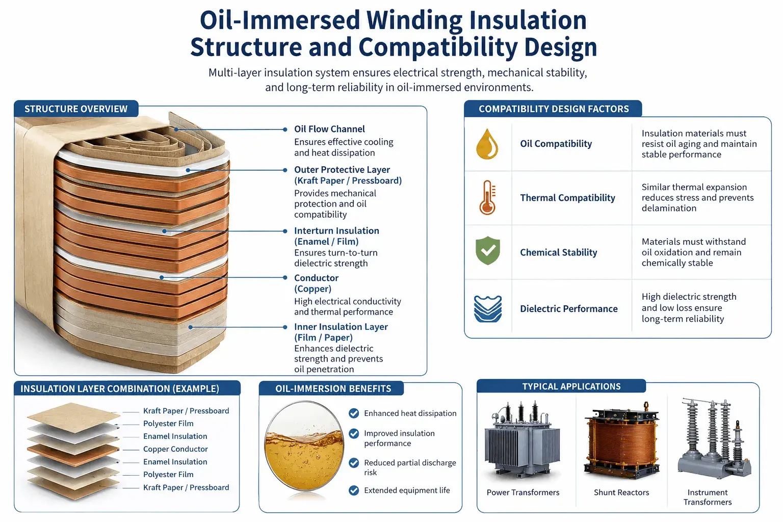
The insulation system of oil-immersed transformer windings employs a paper-oil composite dielectric medium, collaboratively constructed on the core frame using components such as conductors, enamel coatings, paper tapes, transformer oil, insulating paperboards, insulating spacers, and insulating end rings—collectively fulfilling insulation requirements for high-voltage, medium-voltage, and low-voltage windings across electrical, mechanical, thermal, and chemical dimensions.
The operating mechanism of the paper-oil composite insulation is as follows: the porous fibrous structure of the paper-based material adsorbs transformer oil under vacuum impregnation conditions; the oil fills internal air gaps and inter-fiber voids within the paper layers, thereby forming a composite dielectric medium with paper serving as the solid skeleton and oil as the liquid medium. Under electric field stress, the paper layers bear the primary dielectric strength, while the oil fills residual air gaps and provides heat dissipation pathways. The dielectric strength of oil-impregnated paper reaches 50 kV/mm to 60 kV/mm—significantly higher than that of pure oil (10 kV/mm to 15 kV/mm); this substantial dielectric advantage constitutes the fundamental reason for the widespread application of the paper-oil composite system.
The core requirements for paper-covered magnet wire in oil-immersed windings focus on four aspects:
Electrical: The paper-covered magnet wire must maintain sufficient dielectric strength under the combined effects of operating voltage, transient overvoltage, lightning impulse, and switching impulse; its partial discharge inception voltage shall exceed 1.5 times the operating voltage.
Mechanical: Under short-circuit electromagnetic forces, vibration, and thermal expansion stresses, the paper-covered magnet wire must retain insulation layer integrity—preventing cracking, loosening, or delamination.
Thermal: At long-term operating temperatures of 105°C to 120°C and short-term hotspot temperatures of 130°C to 150°C, the paper-covered magnet wire must retain stable dielectric and mechanical properties.
Chemical: The paper-covered magnet wire must be compatible with transformer oil—releasing no acidic substances upon prolonged contact, not absorbing oil additives, and generating no significant aging by-products.
Main Structural Forms of Windings for Oil-Immersed Transformers
Cylindrical Winding
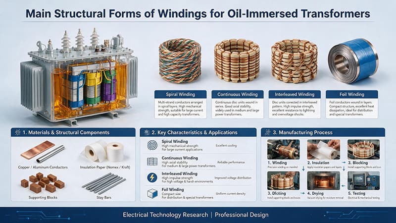
Cylindrical windings consist of multi-layer helical windings made from rectangular or round conductors, with interlayer insulation provided by insulating paperboard or insulating paper strips. This structure is typical for low-voltage and medium-voltage windings rated from 0.4 kV to 35 kV. Cylindrical windings feature simple construction, mature winding processes, and good heat dissipation capability. For paper-covered magnet wire, requirements include coordinated design of interlayer and turn-to-turn insulation; paper tape tension must be uniform, and the winding must be tight and flat during winding.
Pancake Winding
Pancake (Disc) windings consist of rectangular conductors wound radially in a spiral configuration, with each pancake comprising multiple turns and separated from adjacent pancakes by insulating spacers and oil ducts; this is a typical construction for high-voltage and extra-high-voltage windings. Pancake windings commonly employ Continuously Transposed Conductors (CTCs), which are composed of multiple enameled rectangular wires collectively wrapped with insulating paper. CTCs significantly reduce eddy-current losses and circulating-current losses in large power transformers rated at 220 kV and above. Requirements for paper-wrapped conductors include uniformity of the paper tape, interlayer adhesion between paper layers, bendability during winding, and impregnation permeability.
Helical Winding
Helical windings consist of multiple parallel rectangular conductors wound helically along the axial direction, with oil ducts formed between conductors using insulated spacers. This configuration is typical for low-voltage windings in large power transformers. Helical windings feature high current density, large conductor cross-sectional area, and wide heat-dissipation channels. Paper-covered magnet wire typically employs single or multiple parallel rectangular paper-covered copper or aluminum conductors, with relatively few paper layers but stringent mechanical strength requirements. End-treatment and transposition compensation of helical windings are critical to short-circuit withstand capability.
Continuous Winding
Continuous disc windings consist of one or more rectangular conductors wound continuously around the circumference; conductors are transposed between discs via “S-bends” to equalize current distribution, representing a core technology for EHV and UHV windings. Paper-covered magnet wire for continuous disc windings employs high-dielectric-strength cable paper or polyester film-paper composite materials; the number of paper layers is determined by the voltage class, reaching several dozen layers for UHV continuous disc windings. Requirements for paper-covered magnet wire used in continuous disc windings include uniformity of dielectric strength, continuity of paper tape lap joints, stability of winding tension, and completeness of impregnation.
Foil Winding
Foil windings—composed of alternating layers of copper or aluminum foil and insulating paper—are another typical construction for low-voltage, high-current windings. Foil windings offer high space utilization, uniform current distribution, and superior heat dissipation, making them suitable for specialty transformers handling high currents, such as electric furnace transformers and rectifier transformers. Foil windings impose stringent requirements on the dielectric strength, mechanical strength, and impregnability of the insulating paper.
Materials and Manufacturing of Paper-Insulated Wire for Oil-Immersed Windings
Conductor Materials and Base Coating
Conductors for paper-covered enameled wire used in oil-immersed transformer windings are primarily electrolytic-tough-pitch copper (ETP) and oxygen-free copper (OFC); electrical aluminum (1350 series) is employed in certain low-voltage distribution transformers. Copper conductors offer high electrical conductivity, high mechanical strength, excellent ductility, and good solderability, making them the preferred material for high-voltage and extra-high-voltage windings; OFC exhibits superior electrical conductivity and oxidation resistance, rendering it a critical material for high-end power transformer windings. Aluminum conductors feature lower cost and reduced weight, making them suitable for large-size transformers and distribution transformers where weight sensitivity is critical. Conductor cross-sections may be round, rectangular, or segmental, each suited to specific winding configurations. The base enamel layer—the first insulation layer of paper-covered wire—commonly comprises polyester, polyurethane, polyester-imide, or polyamide-imide, with typical thicknesses ranging from 0.02 mm to 0.10 mm. This layer serves multiple functions: filling microscopic surface imperfections of the conductor, enhancing paper tape adhesion, and providing a sealed surface for impregnation.
Paper Substrate Selection
The paper-based materials used for paper-covered magnet wire in oil-immersed windings primarily include cable paper, thermally upgraded kraft paper, aramid paper, and polyester film-paper composite materials. Cable paper is manufactured from unbleached sulfate wood pulp and has a long-term operating temperature of 105°C, serving as the traditional paper-based material for oil-immersed transformers. Thermally upgraded kraft paper achieves a thermal class exceeding 130°C through the addition of thermal stabilizers or chemical modification, thereby maintaining stable physical and electrical properties at elevated temperatures. Aramid paper, made from aromatic polyamide fibers, attains a thermal class up to 220°C and is mainly employed in high-temperature oil-immersed transformers and specialty transformers. Polyester film-paper composite materials combine the high dielectric strength of film with the flexibility of paper, finding application potential in oil-immersed windings rated from 35 kV to 110 kV. Selection of paper-based materials shall comprehensively consider voltage class, operating temperature, insulation requirements, and cost.
Paper Tape Wrapping Process
Paper tape winding is the core process in manufacturing paper-covered magnet wire for oil-immersed windings. The paper tape must be wound tightly, uniformly, and continuously onto the conductor, with an overlap ratio of not less than 40 %; the number of paper tape layers, tension, and winding angle must strictly comply with technical specifications. Defects such as wrinkles, misalignment, overlapping, and cracking must be avoided during winding. Winding equipment typically employs CNC tape-winding machines capable of precisely controlling paper tape tension, speed, and overlap position. Ambient temperature and humidity during winding must be strictly controlled to prevent moisture absorption by the paper substrate or electrostatic charge accumulation on the paper tape.
Dielectric and Mechanical Synergy of Paper-Oil Composite Insulation
Dielectric and Electrical Synergy
The dielectric strength of the paper–oil composite system is determined by the combined performance of the oil gap, paper layers, and oil-impregnated paper. A composite insulation structure is formed by alternating multiple layers of paper tape with oil ducts; the overall dielectric strength is significantly enhanced through an optimized combination of the number of paper layers and oil duct thickness. Electrical performance requirements for paper-covered magnet wire in oil-immersed windings include dielectric breakdown voltage, partial discharge, dielectric loss, volume resistivity, and surface resistivity. The partial discharge inception voltage shall be tested per IEC 61262 and must exceed 1.5 times the operating voltage. The dielectric loss factor (tanδ) is a critical parameter for evaluating the quality of the paper–oil composite insulation; for new windings, tanδ shall be below 0.005, and the trend of tanδ increase during service is a key indicator for assessing insulation aging.
Mechanical and Thermochemical Synergy
The mechanical properties of oil-immersed windings are jointly determined by the conductor, paper-covered wire, insulating spacers, and insulating end rings. The short-circuit electromagnetic force is the most critical mechanical load acting on the winding, and its axial and radial components exert compressive, tensile, and shear stresses on the winding insulation. Standards such as NEMA MW 1000 and GB/T 7672 specify requirements for the bending performance, adhesion performance, and peel strength of paper-covered wire. The overall mechanical performance of oil-immersed windings is verified via short-circuit testing; the inductance change, reactance change, and partial discharge level before and after the test must comply with technical specifications. At the thermochemical level, the aging mechanism of cellulose paper in oil primarily involves thermal degradation and oxidation reactions, with major aging by-products including water, carbon dioxide, furfural, and various organic acids. According to Montsinger’s rule, the service life of oil-immersed paper is approximately halved for every 8°C to 10°C increase in temperature. Key measures to retard aging of oil-immersed paper include controlling oil temperature, reducing moisture content in the oil, and excluding air.
Oil-Immersed Winding Insulation Structure and Compatibility Design
Longitudinal Insulation and Transverse Insulation Compatibility
The insulation coordination design for oil-immersed windings is divided into two main categories: longitudinal insulation and radial insulation. Longitudinal insulation refers to the insulation between turns, between layers, between discs, and between sections within the winding. Turn-to-turn insulation consists of the enamel coating plus single- or double-layer paper tape, withstanding inter-turn voltages ranging from several tens to several hundreds of volts. Layer-to-layer insulation consists of insulating pressboard or insulating paper strips, withstanding layer-to-layer voltages ranging from several hundreds to several thousands of volts. Disc-to-disc insulation consists of insulating spacers and oil ducts, withstanding disc-to-disc voltages ranging from several thousands to several tens of kilovolts. Section-to-section insulation consists of insulating end rings or insulating cylinders, withstanding section-to-section voltages exceeding several tens of kilovolts. Radial insulation refers to the insulation between the winding and ground, between phases, and between windings. Winding-to-ground insulation consists of insulating cylinders, insulating end rings, and insulating pressboard; phase-to-phase insulation consists of phase-separating insulating cylinders and insulating pressboard; and winding-to-winding insulation consists of insulating cylinders and insulating end rings. The coordination between longitudinal and radial insulation in oil-immersed windings must be comprehensively validated via electric field simulation, insulation testing, and operational experience; key parameters include insulation thickness, number of paper layers, oil duct width, and electric field distribution uniformity.
Electric Field Distribution and Corona Suppression
The electric field distribution in oil-immersed windings is comprehensively influenced by conductor geometry, insulation structure, and oil duct arrangement; electric field concentration readily occurs at corners, sharp edges, and discontinuities, leading to corona discharge and insulation damage. Uniform electric field distribution design constitutes the core technology for insulation design of high-voltage and extra-high-voltage windings. Common measures include using conductors with rounded or chamfered edges, installing electrostatic metal shields or insulating overlays in high-field regions, and optimizing oil duct width and the shape of insulation end rings. Regarding corona suppression, windings shall undergo vacuum-pressure impregnation (VPI) to eliminate voids within the insulation layer; transformer oil must undergo rigorous degassing and filtration; and the surfaces of windings and insulation components must be maintained clean and dry.
Critical Manufacturing Processes for Oil-Immersed Windings
Key manufacturing processes for oil-immersed windings comprise four stages: pre-winding treatment, winding, vacuum pressure impregnation (VPI), and drying/assembly.
During the pre-winding treatment stage, incoming materials—including conductors, insulating paper, insulating pressboard, insulating spacers, and insulating end rings—are subjected to incoming inspection. Incoming inspection covers conductor resistivity, dimensional accuracy, surface quality, and mechanical properties; for insulating paper and pressboard, parameters include thickness, density, moisture content, tensile strength, and dielectric strength. Qualified materials are stored in a dry, clean environment with controlled temperature and humidity. Prior to winding, paper-covered conductors undergo vacuum drying at 80°C to 100°C for more than 24 hours to ensure paper moisture content remains below 0.5%.
Winding is performed on dedicated winding machines equipped with CNC systems, tension control systems, and in-line monitoring systems. During winding, conductor tension, paper-covered conductor tension, winding speed, and interlayer insulation placement are strictly controlled. For cylindrical windings, continuity of interlayer insulation is emphasized; for disc-type windings, the “S-bend” quality of transposed conductors is critical; for helical windings, proper end-turn transposition and insulating spacer placement are prioritized; and for continuous windings, integrity of inter-section insulation is essential.
Vacuum Pressure Impregnation (VPI) is a critical process in oil-immersed winding manufacturing. First, a vacuum of less than 100 Pa is drawn and maintained for several hours to remove internal gases and moisture from the insulation system; then, de-aerated transformer oil is introduced to fully submerge the winding; finally, pressure is applied to 0.5 MPa–1.0 MPa and held for several hours to ensure oil penetration into every void within the insulation system. Key VPI process parameters—including vacuum level, pressure, temperature, time, and oil cleanliness—directly determine the winding’s dielectric strength, partial discharge level, and long-term reliability.
Key Performance Testing and Quality Control
Key performance tests for oil-immersed windings include dielectric breakdown, partial discharge, temperature rise, short-circuit withstand, and dissolved gas analysis (DGA) in oil—five core parameters.
Dielectric breakdown testing is conducted per IEC 60851 and NEMA MW 60-A, with NEMA MW 60-A specifying a minimum breakdown voltage of 300 V per mil of paper insulation thickness. Partial discharge testing is performed at power frequency using calibration methods and test circuits specified in IEC 61262; the partial discharge inception voltage (PDIV) of high-voltage windings shall exceed 1.5 times the operating voltage. Temperature rise testing is carried out under rated load and rated cooling conditions; the average temperature rise limit for oil-immersed windings is typically 65 K, and the hot-spot temperature rise limit is typically 78 K.
Short-circuit withstand testing represents the highest-level verification of an oil-immersed winding’s short-circuit resistance. Testing follows the short-circuit current magnitude and duration specified in IEC 60076-5; after testing, the winding shall exhibit no deformation, no insulation damage, and no significant change in reactance. Dissolved gas analysis (DGA) detects concentrations and ratios of gases—including hydrogen, methane, ethane, ethylene, and acetylene—in the insulating oil to identify potential defects such as partial discharge, overheating, and arcing within the winding. DGA is a core methodology for assessing winding insulation condition, predicting potential failures, and guiding maintenance decisions.
Typical Application Cases
Oil-immersed transformers span a wide range—from distribution transformers, power transformers, to large-scale power transformers and special-purpose transformers—where winding requirements for paper-covered magnet wire vary significantly depending on voltage class and capacity rating.
For distribution transformers (10 kV to 35 kV), windings are predominantly cylindrical or foil-type, utilizing thermally upgraded kraft paper-covered enameled copper or aluminum wire, typically with 2 to 4 paper layers.
For power transformers (110 kV to 500 kV), high-voltage windings are mainly disc-type, continuous-type, or transposed conductor coils, employing cable paper or polyester film-paper-covered enameled copper wire with 4 to 12 paper layers and high dielectric strength.
For large-scale power transformers (500 kV to 1000 kV), windings are primarily continuous-type or multi-layer cylindrical, with paper layer counts reaching several dozen, integrated with insulating cylinders, insulating pressboard, electrostatic shields, and molded insulation components to form a complete longitudinal and main insulation system.
Special oil-immersed transformers—including electric furnace transformers, rectifier transformers, and traction transformers—impose specific requirements on paper-covered magnet wire. Electric furnace transformer wire must exhibit high overload capability, high short-circuit resistance, and high mechanical strength to withstand frequent short circuits and current surges inherent in electric furnace operation. Rectifier transformer wire must possess high dielectric strength and high temperature resistance to endure additional stresses induced by harmonic voltages and harmonic currents. Traction transformer wire must deliver high overload capability, high vibration resistance, and high long-term reliability to meet the unique operational conditions of rail transit systems.
Failure Modes and Improvement Directions
Common failure modes of oil-immersed windings include insulation breakdown, partial discharge, paper layer delamination, thermal aging, and mechanical cracking. Insulation breakdown is primarily caused by insufficient paper tape thickness, inadequate lap ratio, defects in the paper substrate material, or incomplete impregnation. Partial discharge arises from voids within the insulation layer, electric field concentration at conductor edges, or incomplete impregnation. Paper layer delamination results from insufficient adhesion between the enamel coating and the paper tape or mismatched coefficients of thermal expansion. Thermal aging and mechanical cracking represent cumulative damage under long-term operating conditions.
To address these failure modes, improvement strategies include optimizing the formulation and processing of paper substrate materials; enhancing adhesion between the enamel coating and paper tape; refining winding processes to improve paper tape uniformity and lap ratio; strengthening vacuum-pressure impregnation (VPI) to eliminate voids and moisture; and improving in-line and final quality inspection systems. At the material level, ceramifiable silicone rubber paper forms a ceramic protective layer at elevated temperatures; nano-modified cellulose paper incorporates nanofillers to increase dielectric strength and mechanical strength; and composite structures combining polyimide film with aramid paper integrate the high dielectric strength of film with the flexibility of paper. At the process level, automated winding equipment and in-line inspection systems enhance consistency and reliability in winding manufacturing; machine vision technology enables real-time monitoring of paper tape winding quality; and artificial intelligence algorithms predict insulation lifetime based on historical data.
Conclusion
Oil-immersed transformer windings are the core components in power transformer manufacturing, and their insulation level directly determines the equipment’s dielectric reliability, short-circuit withstand capability, thermal stability, and long-term reliability. Paper-covered magnet wire—serving as a critical insulation material for oil-immersed windings—collaborates with transformer oil, insulating paperboard, insulating spacers, and insulating end rings to form a complete paper-oil composite insulation system. Cylindrical, disc-type, helical, continuous, and foil-type windings impose differentiated requirements on paper-covered magnet wire across multiple dimensions, including conductor cross-section, number of paper tape layers, paper substrate material, and mechanical strength. Dielectric coordination, mechanical coordination, and thermochemical coordination constitute the core of oil-immersed winding insulation design; dielectric breakdown testing, partial discharge testing, temperature-rise testing, short-circuit withstand testing, and dissolved gas analysis (DGA) in oil are key quality control methods. As power transformers evolve toward higher voltage ratings, greater capacity, and enhanced reliability, the integration of novel paper-based materials, automated manufacturing processes, and intelligent inspection technologies will provide broader development opportunities for insulation design and manufacturing of oil-immersed windings.