


Introduction: Why Single and Double Paper Covered Wire Must Be Treated Differently
In the manufacturing of oil-immersed transformers, dry-type transformers, and various high-voltage windings, paper covered wire has long served as one of the most fundamental and reliable insulation media. Paper covered wire consists of a conductive core (copper or aluminum) with multiple layers of insulating paper wrapped around its exterior. With its excellent electrical insulation properties, good oil-impregnation compatibility, and mature, stable manufacturing process, paper covered wire has become the standard insulation form for critical equipment such as power transformers, reactors, and instrument transformers.
However, in actual engineering practice, engineers frequently face a critical decision: Should single paper covered wire or double paper covered wire be selected?
Although these two types of paper covered wire appear visually similar, differing by only one additional layer of insulating paper, there are significant differences across multiple dimensions including structure, electrical performance, mechanical performance, thermal performance, application scenarios, manufacturing process, cost, and standard requirements. This difference is far more complex than simply “adding one more layer of paper.” It directly affects the transformer’s insulation reliability, operational lifespan, space occupation, manufacturing cost, and ultimately the failure rate and maintenance cycle.
1. Basic Concepts of Paper Covered Wire and the Definition of Single/Double Layers
Before diving into the comparison, let us first clarify the basic concept of “paper covered wire” itself, as well as the standard definitions of “single layer” and “double layer,” to avoid terminology ambiguity in subsequent discussions.
1.1 What Is Paper Covered Wire
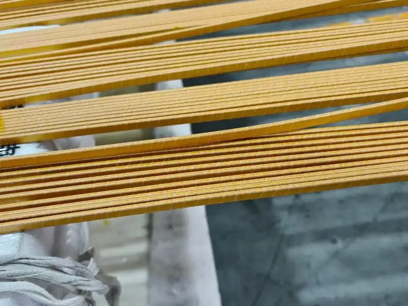
Paper covered wire refers to winding insulation wire manufactured by tightly helically wrapping one or more layers of insulating paper around the exterior of a conductive core (typically copper conductor, but aluminum conductor is also possible). Paper covered wire is one of the most traditional insulation forms for transformer windings, with over 100 years of application history.
Core characteristics of paper covered wire include:
- Insulation Material: Insulating paper with cellulose as the main component. Common types include Kraft Paper, Crepe Paper, Dotted Paper, and Nomex Paper (aromatic polyamide paper).
- Wrapping Method: Through dedicated paper-wrapping machines, the insulating paper tape is tightly wound around the conductor in a helical pattern. A certain overlap ratio is formed between paper tapes, typically 30%–60%.
- Operating Environment: Usually impregnated in transformer oil (mineral oil, synthetic ester, silicone oil, etc.) for operation. It can also be used in dry-type transformers, but in such cases, higher-grade insulating paper is typically required.
- Function: Provides inter-turn, inter-layer, and ground insulation for windings, withstands operating voltage and short-time overvoltage, and provides certain mechanical protection.
1.2 Definition of Single Paper Covered Wire
Single Paper Covered Wire refers to paper covered wire that wraps only 1 layer of insulating paper around the exterior of the conductive core.
- Structure: Conductor + 1 layer of insulating paper tape (helical wrapping).
- Thickness: Total paper layer thickness typically ranges from 0.05mm to 0.15mm (depending on paper basis weight and overlap ratio).
- Code Identification: In different standards, single paper covered wire is typically denoted as “P1” or “1P”, for example “CU/P1” indicates single-layer paper covered copper wire.
- Typical Applications: Low-voltage windings, small transformers, instrument transformer secondary sides, control transformers, etc.
1.3 Definition of Double Paper Covered Wire
Double Paper Covered Wire refers to paper covered wire that wraps 2 layers of insulating paper around the exterior of the conductive core.
- Structure: Conductor + 2 layers of insulating paper tape (can be two layers of the same type of paper, or a combination of two different types of paper).
- Thickness: Total paper layer thickness typically ranges from 0.15mm to 0.30mm, approximately 2 times that of single layer.
- Code Identification: Commonly denoted as “P2” or “2P”, for example “CU/P2” indicates double-layer paper covered copper wire.
- Typical Applications: High-voltage windings, power transformers, large distribution transformers, oil-immersed reactors, high-voltage instrument transformers, etc.
1.4 Extended Concept of Multi-Layer Paper Covered Wire
For completeness, let us briefly mention the extended concept of multi-layer paper covered wire. Beyond single and double layers, three-layer or even more layers of paper covered wire also exist in engineering (for example, three-layer paper covered wire coded as P3, mainly used for EHV and UHV windings). However, single and double layers are the two most common and widely used types in engineering. Therefore, this article focuses on the comparison between these two.
2. Dimension One: Structural Differences—Wrapping Layers, Overlap Ratio, and Insulation Thickness
Structure is the most direct and essential difference between single and double paper covered wire. This dimension may seem simple, but it contains the “root” parameters that influence all subsequent performance differences.
2.1 Wrapping Layers and Thickness Comparison
| Item | Single Paper Covered Wire | Double Paper Covered Wire |
|---|---|---|
| Wrapping Layers | 1 layer | 2 layers |
| Typical Paper Thickness (per layer) | 0.05mm–0.15mm | 0.05mm–0.15mm |
| Total Paper Layer Thickness | 0.05mm–0.15mm | 0.15mm–0.30mm |
| Outer Diameter Increase (relative to bare wire) | Smaller | Larger |
| Paper Tape Overlap Ratio | Typically 30%–50% | Typically 40%–60% |
Key Point: The reason double paper covered wire requires a higher overlap ratio is that the helical directions of the two paper tape layers are usually opposite (“S-direction + Z-direction” reverse wrapping). Reverse wrapping can prevent the two paper layers from overlapping on the same helical line, allowing voltage stress to be more evenly distributed across the paper layers.
2.2 Reverse Helical Wrapping Process
- Single Paper Covered Wire: The paper tape is typically helically wound in a single direction (clockwise or counterclockwise).
- Double Paper Covered Wire: The winding directions of the first and second layers are typically opposite. This “reverse wrapping” process can:
- Eliminate electric field concentration at the helical seam of single-layer paper tape
- Provide more uniform voltage stress distribution
- Improve overall mechanical stability
2.3 Effect of Insulation Thickness on Outer Diameter
An increase in insulation thickness means an increase in wire outer diameter. For transformer windings, an increase in outer diameter implies:
- Slot Fill Factor Reduction: The conductor cross-sectional area that can be accommodated decreases within the same core window.
- Heat Dissipation Area Increase: Insulating paper itself is a poor thermal conductor, but the microscopic oil gaps between paper layers actually facilitate heat dissipation.
- Overall Size Increase: Transformer volume, weight, and cost all increase accordingly.
Engineering Experience: In 10kV distribution transformers, changing from single paper covered wire to double paper covered wire increases the outer diameter by approximately 0.10mm–0.25mm; in 35kV power transformers, this increase may reach 0.20mm–0.40mm.
2.4 Paper Type Combination Methods
Double paper covered wire can flexibly combine the types of the two paper layers according to needs:
| Combination Method | Typical Application |
|---|---|
| Both layers are Kraft Paper | Economical double paper covered wire, commonly used in medium-voltage distribution transformers |
| Both layers are Crepe Paper | High elasticity requirement scenarios, e.g., windings requiring bending forming |
| Inner layer Kraft + Outer layer Crepe | Balancing mechanical strength and elongation, commonly used in high-voltage windings |
| Inner layer Nomex + Outer layer Kraft | High temperature resistance scenarios, e.g., dry-type transformers, Class H insulation |
| Inner layer Dotted Paper + Outer layer Kraft | Oil duct design scenarios, facilitating insulating oil penetration and circulation |
Single paper covered wire typically uses only a single paper type, with lower combination flexibility.
3. Dimension Two: Electrical Performance Differences—Breakdown Voltage, Dielectric Strength, and Electric Field Distribution
Electrical performance is the most critical dimension distinguishing single from double paper covered wire. In transformers, the primary task of insulating paper is to withstand operating voltage and various overvoltages. Therefore, this dimension directly determines whether paper covered wire can “qualify” for specific voltage levels.
3.1 Breakdown Voltage
Breakdown voltage is the ultimate indicator of the electric field strength that insulation material can withstand. Exceeding this voltage, insulation undergoes irreversible breakdown damage.
| Voltage Level | Single Paper Covered Wire Breakdown Voltage | Double Paper Covered Wire Breakdown Voltage |
|---|---|---|
| Typical Value (kV) | 1.5–3.0 kV | 3.5–7.0 kV |
| Relationship to Layer Count | Baseline | Approximately 1.8–2.5 times that of single layer |
Principle: Breakdown voltage is not linearly related to insulation thickness. The breakdown voltage of double-layer paper is usually slightly lower than the theoretical value of “single layer × 2”, because there are microscopic air gaps and oil gap interfaces between layers. Nevertheless, the breakdown voltage of double paper covered wire is still approximately 2 times that of single layer, sufficient to cover the vast majority of high-voltage application scenarios.
3.2 Dielectric Strength
Dielectric strength is the breakdown voltage per unit thickness of insulation material that can be withstood, typically expressed in kV/mm.
- Kraft Paper Dielectric Strength: Approximately 10 kV/mm in air, improved to approximately 15–20 kV/mm after oil impregnation.
- Single Paper Covered Wire Dielectric Strength: Approximately 15 kV/mm under oil-impregnated conditions.
- Double Paper Covered Wire Dielectric Strength: Due to inter-layer interface effects, the overall dielectric strength is slightly lower than 2 times the single-layer value, but still significantly higher than that of single layer.
3.3 Electric Field Distribution
- Single Paper Covered Wire: Electric field concentrates at the helical seam of the paper tape, easily forming partial discharge (PD).
- Double Paper Covered Wire: Due to reverse wrapping, electric field distribution is more uniform, and the partial discharge inception voltage (PDIV) is significantly increased.
- Numerical Reference: The PDIV of double paper covered wire is typically 30%–50% higher than that of single layer.
3.4 Dielectric Loss Tangent (tan δ)
The dielectric loss tangent (tan δ) reflects the energy loss of insulation media under AC electric fields.
- Single paper covered wire: Due to thinner insulation, tan δ is lower and loss is smaller.
- Double paper covered wire: Due to thicker insulation layers and dielectric constant changes, tan δ is slightly higher than that of single layer, but remains within acceptable range.
- Under 50Hz/60Hz power frequency, the difference in tan δ between the two is typically within 10%–20%.
3.5 Insulation Resistance
Insulation resistance reflects the ability of insulation to impede direct current:
- Single paper covered wire insulation resistance: Typically in the 10^10–10^12 Ω·m range.
- Double paper covered wire insulation resistance: Typically in the 10^11–10^13 Ω·m range, slightly higher than single layer.
Higher insulation resistance means smaller leakage current, which is more beneficial for long-term operational stability and safety.
4. Dimension Three: Mechanical Performance Differences—Flexibility, Bending Radius, and Damage Resistance
Mechanical performance determines whether paper covered wire can maintain insulation integrity during coil winding, transformer assembly, and long-term operation.
4.1 Bending Performance
Paper covered wire must be wound onto iron cores or molds to form coils, a process that imposes strict requirements on the bending performance of the wire.
- Single Paper Covered Wire: With only 1 layer of paper, the paper layer is thin, the overall flexibility is good, and the minimum bending radius is typically 3–5 times the wire diameter.
- Double Paper Covered Wire: With 2 layers of paper stacked, flexibility decreases, and the minimum bending radius is typically 4–7 times the wire diameter.
Engineering Impact: Double paper covered wire is more prone to issues such as paper layer cracking and wrinkling when winding small-sized coils, requiring higher process precision.
4.2 Tensile Strength and Elongation
- Single paper covered wire: Due to the thin paper layer, overall elongation is higher, and paper layer breakage is less likely during stretching.
- Double paper covered wire: The tensile strength is higher after two-layer paper stacking, but elongation decreases, and relative sliding between the paper layer and conductor may occur during stretching.
4.3 Wear Resistance and Impact Resistance
- Single paper covered wire: The paper layer is thin and easily damaged when subjected to external impact.
- Double paper covered wire: Double-layer protection significantly improves wear resistance and impact resistance, providing better resistance to mechanical damage during assembly and transportation.
4.4 Vibration Resistance
Transformers are subject to vibration caused by electromagnetic forces during operation, especially the electrodynamic force impact during short circuits.
- Single paper covered wire: Long-term vibration may cause paper layer fatigue cracking.
- Double paper covered wire: The double-layer structure provides better vibration resistance stability, extending insulation life.
5. Dimension Four: Thermal Performance Differences—Thermal Class, Heat Dissipation, and Oil-Immersion Compatibility
Thermal performance directly affects transformer operating temperature, load capacity, and lifespan.
5.1 Thermal Class
| Class | Single Paper Covered Wire | Double Paper Covered Wire |
|---|---|---|
| Kraft Paper Temperature Resistance | 105°C (Class A) | 105°C (Class A) |
| Temperature Resistance After Oil Impregnation | 105–120°C | 105–120°C |
| Nomex Paper Temperature Resistance | 220°C (Class C) | 220°C (Class C) |
Key Point: Thermal class is mainly determined by the paper type itself, not the number of layers. Therefore, there is no essential difference in thermal class between single and double paper covered wire. However, due to the thicker insulation layer in double-layer structures, the heat dissipation path is longer, and the actual temperature rise is slightly higher than that of single layer.
5.2 Heat Dissipation Performance
- Single paper covered wire: Thin paper layer, low thermal resistance, fast heat dissipation.
- Double paper covered wire: Thick paper layer, high thermal resistance, slightly slower heat dissipation, but the oil gaps between double-layer paper facilitate heat dissipation.
Engineering Experience: Under the same current density, the temperature rise of double paper covered wire windings is typically 3–8°C higher than that of single layer.
5.3 Oil-Immersion Compatibility
- After oil impregnation, the electrical performance of both single and double paper covered wire significantly improves (breakdown voltage increased by more than 50%).
- Double paper covered wire, due to more oil gaps between layers, has better oil penetration and circulation effects, resulting in higher insulation stability during long-term operation.
5.4 Thermal Aging Life
- Single paper covered wire: Thermal aging rate is faster, and the paper layer easily becomes brittle and carbonized under long-term high temperature.
- Double paper covered wire: The double-layer structure delays the conduction of thermal aging toward the conductor body, and thermal aging life is extended by approximately 20%–40% compared to single layer.
6. Dimension Five: Application Scenario Differences—Differentiated Applications from Low Voltage to High Voltage
Application scenarios are the most intuitive differentiation between single and double paper covered wire, and the dimension that engineers care most about during selection.
6.1 Low-Voltage Scenarios (≤1kV)
Recommended: Single paper covered wire
Typical applications:
– Control transformers
– Low-voltage side of small distribution transformers
– Instrument transformer secondary side
– Instrumentation windings
– Electronic transformers
Reason: Low-voltage scenarios have low insulation requirements, and single paper covered wire can meet the demand while offering the advantages of smaller outer diameter and lower cost.
6.2 Medium-Voltage Scenarios (1kV–10kV)
Recommended: Determined according to specific voltage level
– 1–3kV: Single paper covered wire is usually sufficient
– 3–6kV: Double paper covered wire is recommended
– 6–10kV: Double paper covered wire must be used
Typical applications:
– 10kV distribution transformers
– Medium-voltage motor windings
– Mining transformers
6.3 High-Voltage Scenarios (10kV–35kV)
Recommended: Double paper covered wire (mandatory)
Typical applications:
– 35kV power transformers
– High-voltage reactors
– High-voltage instrument transformers
– Large industrial transformers
6.4 Extra-High-Voltage Scenarios (≥66kV)
Recommended: Double paper covered wire + multi-layer combination + Vacuum Pressure Impregnation (VPI) process
Typical applications:
– 110kV, 220kV power transformers
– Extra-high-voltage reactors
– UHV transformers
In extra-high-voltage scenarios, it is usually necessary to wrap additional layers of insulating paper (3 or more layers) outside the double paper covered wire to meet higher electrical insulation requirements.
6.5 Quick-Reference Scenario Comparison Table
| Application Scenario | Voltage Level | Recommended Paper Covered Wire Type | Reason |
|---|---|---|---|
| Control Transformer | ≤1kV | Single Layer | Low voltage, cost-sensitive |
| Small Distribution Transformer | ≤1kV | Single Layer | Low voltage, space-saving |
| 10kV Distribution Transformer | 10kV | Double Layer | Medium-high voltage, requires reliable insulation |
| 35kV Power Transformer | 35kV | Double Layer | High voltage, double layer mandatory |
| 110kV Power Transformer | 110kV | Double Layer + Multi-Layer | Extra-high voltage, requires redundant insulation |
| Dry-Type Transformer Class H | All | Double Layer (Nomex) | High thermal class |
| Oil-Immersed Reactor | All | Double Layer | High electric field strength |
7. Dimension Six: Manufacturing Process Differences—Paper Wrapping, Drying, Adhesive, and Quality Control
Manufacturing process directly affects paper covered wire consistency, reliability, and cost.
7.1 Paper Wrapping Process
- Single Paper Covered Wire: The paper wrapping process is relatively simple, and the wrapping speed can be faster (typically up to 30–80 m/min).
- Double Paper Covered Wire: Requires 2 paper wrapping passes, with slower wrapping speed (typically 15–50 m/min), requiring two overlap alignments, and higher process difficulty.
7.2 Paper Tape Tension Control
- Single paper covered wire: Tension control is relatively loose.
- Double paper covered wire: The tension of both paper layers requires precise independent control. Excessive tension may cause paper layer stretching deformation, while insufficient tension may cause paper layer looseness and wrinkling.
7.3 Adhesive and Bonding
- Some paper covered wires use adhesive (such as epoxy resin, modified starch adhesive) to bond paper layers to the conductor.
- Single paper covered wire: Typically uses less adhesive.
- Double paper covered wire: Adhesive usage increases, requiring stricter drying processes to avoid issues such as bubbles and delamination.
7.4 Drying and Curing
- Single paper covered wire: Shorter drying time.
- Double paper covered wire: Longer drying time and higher energy consumption, but drying quality is critical to insulation stability.
7.5 Quality Control
- Double paper covered wire requires more indicators to be tested: inter-layer adhesion, paper tape tension uniformity, double-layer thickness deviation, electric field uniformity, etc.
- Testing equipment is more complex: online thickness gauges, corona detectors, PDIV testers, etc.
8. Dimension Seven: Cost Differences—Material, Process, and Total Lifecycle Cost
Cost is an unavoidable key factor in industrial selection.
8.1 One-Time Cost
| Cost Item | Single Paper Covered Wire | Double Paper Covered Wire |
|---|---|---|
| Insulating Paper Material | Baseline (1×) | Approximately 1.8–2.2× |
| Paper Wrapping Process | Baseline (1×) | Approximately 1.5–1.8× |
| Adhesive | Baseline (1×) | Approximately 1.3–1.5× |
| Drying | Baseline (1×) | Approximately 1.2–1.4× |
| Comprehensive One-Time Cost | Baseline (1×) | Approximately 1.6–1.9× |
8.2 Total Lifecycle Cost (TCO)
Although the one-time cost of double paper covered wire is higher, evaluation needs to be conducted from a total lifecycle perspective:
- Reliability Improvement: Double paper covered wire has significantly reduced failure rates, reducing maintenance and replacement costs.
- Extended Lifespan: Thermal aging life is extended by 20%–40%, extending the overall transformer life.
- Reduced Maintenance Cost: Double-layer insulation reduces partial discharge probability, lowering the complexity of periodic inspections.
TCO Conclusion: In high-voltage scenarios, the total lifecycle cost of double paper covered wire is usually lower than that of single layer; in low-voltage scenarios, single paper covered wire has better TCO.
8.3 Selection Economy Principles
- Low-Voltage, Low-Cost Scenarios: Single paper covered wire is the most economical choice.
- Medium-Voltage, High-Reliability Scenarios: Double paper covered wire has better TCO.
- High-Voltage, Critical Equipment Scenarios: Double paper covered wire is the inevitable choice, and one-time cost should not be considered.
9. Dimension Eight: Standard Specification Differences—IEC, GB, IEEE Definitions of Single/Double Layers
Different standards have different codes, naming, and testing requirements for single and double paper covered wire.
9.1 IEC Standard (International Electrotechnical Commission)
- IEC 60317: Insulation winding wire standard, which includes specific specifications for paper covered wire.
- Single paper covered wire code is typically P1.
- Double paper covered wire code is typically P2.
- The IEC standard has clear provisions for paper thickness, overlap ratio, and breakdown voltage.
9.2 GB Standard (Chinese National Standard)
- GB/T 7673: National standard for paper covered winding wire, corresponding to IEC 60317.
- Single paper covered wire code: P1.
- Double paper covered wire code: P2.
- The GB standard has detailed provisions for paper covered wire identification, testing methods, and acceptance rules.
9.3 IEEE Standard (Institute of Electrical and Electronics Engineers)
- The IEEE standard focuses more on paper covered wire application and performance testing in transformers, with less detailed definition of layer count than IEC/GB, but provides substantial application-level guidance.
9.4 NEMA Standard (National Electrical Manufacturers Association)
- NEMA MW 31–MW 33 and other standards cover paper covered wire, with different specification requirements for single and double layers.
9.5 Quick-Reference Standard Comparison Table
| Standard | Single Layer Code | Double Layer Code | Main Application Region |
|---|---|---|---|
| IEC 60317 | P1 | P2 | Europe, Global |
| GB/T 7673 | P1 | P2 | China |
| NEMA MW | MW31 etc. | MW33 etc. | North America |
| JIS C3202 | 1P | 2P | Japan |
10. Single/Double Paper Covered Wire Selection Decision Table
To facilitate engineers’ rapid selection, we have compiled the following decision table:
10.1 Selection Decision Table
| Decision Dimension | Choose Single Layer P1 | Choose Double Layer P2 |
|---|---|---|
| Operating Voltage | ≤3kV | ≥6kV |
| Equipment Type | Control transformer, small distribution | Power transformer, large distribution |
| Insulation Redundancy Requirement | General | High |
| Space Constraint | Compact | Insensitive |
| Cost Constraint | Strict | General |
| Lifespan Requirement | 10–20 years | ≥30 years |
| Failure Rate Requirement | <5% | <1% |
| Short-Circuit Resistance | General | High |
| Environmental Humidity | Dry | Any |
| Standard Requirement | IEC/GB P1 | IEC/GB P2 |
10.2 Selection Decision Flowchart
Operating Voltage?
  ├─ ≤3kV → Single Layer P1
  ├─ 3–6kV → Evaluate reliability requirements → Single Layer P1 or Double Layer P2
  └─ ≥6kV → Double Layer P2 (mandatory)

Equipment Type?
  ├─ Control/Small → Single Layer P1
  ├─ Distribution → Double Layer P2
  └─ Power → Double Layer P2 or more layers

Cost Constraint?
  ├─ Strict + Low voltage → Single Layer P1
  └─ General + Medium-high voltage → Double Layer P2

Lifespan Requirement?
  ├─ ≤20 years + Low voltage → Single Layer P1
  └─ ≥30 years + Any voltage → Double Layer P2
11. Practical Case Comparison: Two Engineering Examples
11.1 Case 1: 10kV Distribution Transformer
Background: A power company needed to procure 100 10kV distribution transformers, with windings using paper covered copper wire.
Selection Process:
– Voltage level 10kV, the breakdown voltage of single paper covered wire is insufficient to meet the demand.
– Double paper covered wire (P2) was selected, with higher insulation reliability.
– The increase in outer diameter of double paper covered wire was compensated by adjusting the core window size.
Results:
– First-time commissioning qualification rate reached 99.5%.
– Failure rate was 0 within 5 years.
– Compared with the single-layer solution, total lifecycle cost was reduced by approximately 12%.
11.2 Case 2: 400V Control Transformer
Background: An automation equipment manufacturer needed to procure 10,000 400V control transformers.
Selection Process:
– Voltage level only 400V, belonging to low-voltage scenarios.
– Single paper covered wire was sufficient to meet insulation requirements.
– Single paper covered wire (P1) was selected to maximize cost advantages.
Results:
– Per-unit cost reduced by approximately 25%.
– Failure rate <0.5% within 5 years.
– Overall project cost savings exceeded RMB 1 million.
11.3 Case Comparison Insights
- High-voltage scenarios must use double paper covered wire, which is the “bottom line” of insulation reliability.
- Low-voltage scenarios prioritize single paper covered wire, which is the “upper limit” of cost optimization.
- Medium-voltage scenarios require comprehensive consideration of four factors: voltage, lifespan, reliability, and cost.
12. Future Trends and Development Directions
12.1 Application of High-Temperature-Resistant Paper Types
With the growing demand for dry-type transformers and Class H and above transformers, the combined application of high-temperature-resistant paper types such as Nomex and Kapton with double paper covered wire structures is increasing.
12.2 Composite Insulation Structures
Composite insulation structures such as “paper + enamel,” “paper + film,” and “paper + mica” are challenging traditional pure paper covered wire solutions, but paper covered wire still dominates in the oil-immersed transformer field.
12.3 Intelligent Manufacturing
Online thickness measurement, online PD detection, AI visual defect recognition, and other technologies are being introduced into paper covered wire production, further improving the consistency and reliability of double paper covered wire.
12.4 Green Environmental Protection
With increasing environmental protection requirements, green solutions such as adhesive-free paper covered wire, degradable insulating paper, and recycled paper-based materials are gradually moving toward engineering applications.