


1 Introduction
Data center is the key carrier of strategic digital infrastructure including cloud computing, big data, artificial intelligence, 5G communication, internet, financial transaction, which determines the safe operation of digital business through the continuity, stability, reliability of its power system. Data center power system covers medium voltage distribution, transformer, UPS, PDU, server power supply, switch power supply, high frequency transformer, inductor and other key equipment.
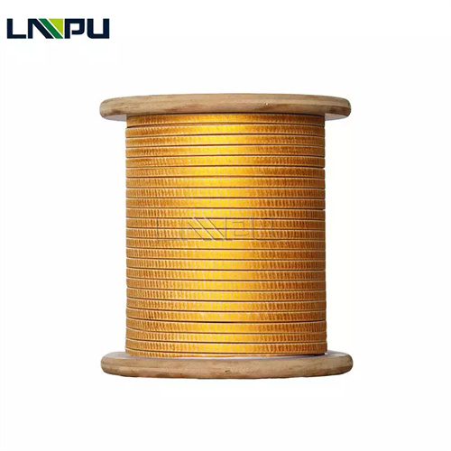
Fiberglass covered wire is the heat resistant insulated winding wire using glass fiber silk weaving or wrapping, combined with polyester, polyesterimide, polyamideimide enamel film, paper wrapping, enameled composite insulation process, is the key raw material for data center transformer, inductor, filter, high frequency power magnetic element. Fiberglass covered wire heat resistance class 130 to 220 degrees Celsius, dielectric strength 5000 to 25000 V per mm, service life not lower than 20 years, is the preferred material for data center high frequency, high power density, high reliability magnetic element design.
Based on IEC 60317, IEC 60076, IEC 62040, UL 1561, IEEE 1188, GB/T 6109, ASTM D 1458 and other international and domestic standards, this article systematically describes the application technology and engineering practice of fiberglass covered wire in data center from seven dimensions including data center and fiberglass covered wire overview, UPS transformer application, PDU and isolation transformer application, server power supply and switch power supply application, high frequency transformer and inductor application, fiberglass covered wire selection and design key points, and summary.
2 Data Center and Fiberglass Covered Wire Overview
2.1 Data Center Power System Architecture
Data center power system covers mains input, medium voltage distribution, transformer, low voltage distribution, UPS, PDU, server power supply, switch power supply, energy storage system, backup generator set, column head cabinet, rack PDU twelve major subsystems.
Mains input usually adopts 10 kV or 35 kV medium voltage power, distributed through medium voltage distribution cabinet to main transformer, stepped down to 400 V low voltage power, then distributed to each floor or each equipment room. Medium voltage transformer capacity 1000 to 5000 kVA, efficiency not lower than 98%, insulation class F or H, temperature rise not exceeding 80 K.
UPS is the key equipment of data center, capacity 100 kVA to 5000 kVA, efficiency not lower than 96%, output voltage 400 V three phase, switching time less than 10 ms, battery backup time 15 to 30 minutes. PDU is the rack internal power distribution equipment, capacity 10 kVA to 100 kVA. Server power supply converts 230 V AC power to 12 V, 5 V, 3.3 V, 1.8 V etc DC power, efficiency not lower than 80 PLUS Titanium standard, power density 50 W per cubic inch above, power factor not lower than 0.95.
2.2 Fiberglass Covered Wire Product System and Technical Advantage
Fiberglass covered wire product system covers fiberglass covered round copper wire, fiberglass covered enameled rectangular copper wire, fiberglass paper covered rectangular copper wire, fiberglass covered aluminum wire four major categories.
Fiberglass covered round copper wire conductor diameter 0.50 to 5.00 mm, fiberglass braiding layer thickness 0.10 to 0.30 mm, heat resistance class 130 to 180 degrees Celsius. Fiberglass covered enameled rectangular copper wire conductor width 2.00 to 16.00 mm, thickness 0.80 to 5.60 mm, heat resistance class 155 to 200 degrees Celsius. Fiberglass paper covered rectangular copper wire heat resistance class 180 to 220 degrees Celsius. Fiberglass covered aluminum wire weight reduced 70%, cost reduced 30 to 50%.
Fiberglass covered wire technical advantage covers heat resistance, dielectric strength, mechanical strength, thermal shock, space utilization, reliability, service life, environmental adaptability eight major dimensions. Mechanical strength tensile strength increase 30 to 50%, space utilization improved 5 to 15% over enameled wire, accelerated aging 200 degrees Celsius 6000 hours above still maintain performance stability.
3 Data Center UPS Transformer Application
3.1 UPS Transformer and Rectification Inversion
UPS key magnetic element includes input transformer, output transformer, rectifier transformer, inverter transformer, isolation transformer, filter inductor. UPS transformer capacity range 100 kVA to 5000 kVA, overall efficiency not lower than 96%, switching time less than 10 ms, harmonic distortion not exceeding 3%.
UPS input transformer capacity 100 to 5000 kVA, primary voltage 10 kV or 35 kV medium voltage or 400 V low voltage, secondary voltage 400 V to 800 V, connection group Dyn11 or Yyn0, adopts dry type transformer structure, insulation class F 155 degrees Celsius or H 180 degrees Celsius.
UPS rectifier transformer capacity 50 to 2000 kVA, primary voltage 400 V to 800 V, secondary voltage 24 V to 600 V DC, insulation class H 180 degrees Celsius. Winding adopts fiberglass covered enameled rectangular copper wire, conductor width 4.00 to 12.00 mm, inter-turn insulation 0.13 to 0.30 mm fiberglass covered layer, inter-layer insulation 0.50 to 2.00 mm insulation pressboard.
UPS output transformer capacity 100 to 5000 kVA, primary voltage 400 V to 800 V, secondary voltage 400 V three phase, connection group Dyn11, insulation class H 180 degrees Celsius. Winding adopts fiberglass covered enameled rectangular copper wire, conductor width 4.00 to 16.00 mm, inter-turn insulation 0.15 to 0.30 mm fiberglass covered layer, inter-layer insulation 1.0 to 3.0 mm DMD or NMN composite paper.
3.2 UPS Inversion Isolation and Filter Inductor
UPS inverter transformer working frequency 20 kHz to 100 kHz, adopts ferrite core, winding adopts Litz wire or fiberglass covered enameled round copper wire, conductor diameter 0.50 to 2.00 mm, turn number 10 to 100 turns, insulation class H 180 degrees Celsius.
UPS isolation transformer capacity 10 to 500 kVA, primary voltage 400 V, secondary voltage 400 V, insulation class H 180 degrees Celsius, isolation voltage not lower than 4000 V, common mode rejection ratio not lower than 60 dB. Winding adopts fiberglass covered enameled rectangular copper wire, conductor width 2.00 to 8.00 mm, thickness 1.00 to 3.15 mm, inter-turn insulation 0.15 to 0.25 mm fiberglass covered layer, shield layer adopts copper foil or aluminum foil.
4 Data Center PDU and Isolation Transformer Application
4.1 PDU Main Transformer and Isolation
PDU type covers basic PDU, metering PDU, monitoring PDU, switch PDU, intelligent PDU. Key parameter includes input voltage 400 V three phase or 230 V single phase, output voltage 230 V single phase, rated current 16 A to 63 A, configuration monitoring and remote management function, overload protection, short circuit protection, leakage protection, surge protection.
PDU main transformer capacity 10 to 100 kVA, primary voltage 400 V three phase, secondary voltage 230 V single phase, insulation class F 155 degrees Celsius or H 180 degrees Celsius. Winding adopts fiberglass covered enameled rectangular copper wire, conductor width 2.00 to 6.00 mm, thickness 1.00 to 3.15 mm, inter-turn insulation 0.10 to 0.20 mm fiberglass covered layer.
PDU isolation transformer capacity 5 to 50 kVA, primary voltage 230 V, secondary voltage 230 V, insulation class H 180 degrees Celsius, isolation voltage not lower than 3000 V, common mode rejection ratio not lower than 50 dB. Winding adopts fiberglass covered enameled rectangular copper wire, conductor width 1.50 to 4.00 mm, thickness 0.80 to 2.00 mm, inter-turn insulation 0.10 to 0.20 mm fiberglass covered layer.
4.2 PDU Instrument Transformer, Column Head Cabinet and Rack Transformer
PDU monitoring adopts voltage instrument transformer and current instrument transformer, capacity 5 to 50 VA, accuracy class 0.5 to 1.0. PDU instrument transformer winding adopts fiberglass covered enameled round copper wire, conductor diameter 0.20 to 1.00 mm, turn number 50 to 2000 turns, insulation layer 0.05 to 0.15 mm fiberglass covered layer.
Column head cabinet is the power distribution equipment at data center equipment room column head or column tail, input 400 V three phase, output 230 V single phase, capacity 50 to 200 kVA. Rack internal transformer converts 230 V single phase to 12 V, 24 V, 48 V DC, capacity 500 VA to 5000 VA, insulation class F 155 degrees Celsius or H 180 degrees Celsius. Winding adopts fiberglass covered enameled round copper wire or rectangular copper wire, conductor diameter 0.30 to 2.00 mm, inter-turn insulation 0.08 to 0.15 mm fiberglass covered layer, shield layer adopts copper foil.
5 Data Center Server Power Supply and Switch Power Supply Application
5.1 PFC Inductor and Main Transformer
Server power supply type covers ATX power supply, CRPS power supply, SSI power supply, redundant power supply, modular power supply. Key parameter includes input voltage 100 to 240 V AC, rated power 300 to 3000 W, efficiency not lower than 80 PLUS Titanium 96%, power factor not lower than 0.95, ripple noise not exceeding 1%, hold time not lower than 12 ms.
PFC inductor capacity 100 to 2000 W, working frequency 65 to 300 kHz, core adopts iron powder core or iron silicon aluminum powder core, insulation class H 180 degrees Celsius. Winding adopts fiberglass covered enameled round copper wire or Litz wire, conductor diameter 0.30 to 1.50 mm, turn number 10 to 100 turns, insulation layer 0.10 to 0.20 mm fiberglass covered layer.
Main transformer capacity 300 to 3000 W, working frequency 65 to 500 kHz, core adopts ferrite, insulation class H 180 degrees Celsius. Winding adopts fiberglass covered enameled round copper wire or Litz wire, conductor diameter 0.20 to 1.00 mm, turn number 5 to 50 turns, insulation layer 0.10 to 0.20 mm fiberglass covered layer, shield layer adopts copper foil or sandwich winding structure.
5.2 Resonant Inductor, Auxiliary Drive Transformer
Resonant inductor capacity 300 to 3000 W, working frequency 65 to 500 kHz, resonant frequency 80 to 300 kHz, core adopts ferrite, insulation class H 180 degrees Celsius. Winding adopts fiberglass covered enameled round copper wire or rectangular copper wire, conductor diameter 0.30 to 1.20 mm, turn number 5 to 30 turns, insulation layer 0.10 to 0.20 mm fiberglass covered layer, resonant inductance 10 to 200 μH, quality factor not lower than 100. Output filter inductor capacity 100 to 2000 W, core adopts iron powder core or ferrite, insulation class H 180 degrees Celsius, output filter inductance 1 to 50 μH, conductor diameter 0.30 to 1.50 mm, turn number 10 to 50 turns.
Auxiliary power supply capacity 5 to 50 W, working frequency 65 to 200 kHz. Drive transformer capacity 1 to 10 W, isolation voltage not lower than 2500 V. Auxiliary drive transformer winding adopts fiberglass covered enameled round copper wire, conductor diameter 0.10 to 0.50 mm, turn number 5 to 200 turns, insulation layer 0.05 to 0.10 mm fiberglass covered layer.
6 Data Center High Frequency Transformer and Inductor Application
6.1 DC-DC Module and 48 V Bus Converter
Data center high frequency transformer includes server power supply high frequency transformer, DC-DC module power supply high frequency transformer, 48 V bus converter high frequency transformer, PoE power supply high frequency transformer, communication power supply high frequency transformer, UPS high frequency transformer six categories. Capacity range 50 W to 5000 W, working frequency 50 kHz to 1 MHz, core adopts ferrite, nanocrystalline, insulation class H 180 degrees Celsius to N 220 degrees Celsius.
DC-DC module power supply capacity 50 to 2000 W, input voltage 48 V, efficiency not lower than 95%, insulation voltage not lower than 1500 V. High frequency transformer winding adopts fiberglass covered enameled round copper wire or Litz wire, conductor diameter 0.10 to 0.80 mm, turn number 3 to 30 turns, insulation layer 0.05 to 0.15 mm fiberglass covered layer, leakage inductance not exceeding 1% main inductance.
48 V bus converter capacity 500 to 6000 W, input voltage 48 V, efficiency not lower than 97%, power density not lower than 1000 W per cubic inch. High frequency transformer winding adopts fiberglass covered enameled round copper wire or rectangular copper wire, conductor diameter 0.20 to 1.50 mm, turn number 3 to 20 turns, insulation layer 0.10 to 0.20 mm fiberglass covered layer, adopts planar transformer or PCB winding structure.
6.2 Communication PoE and Power EMI Filter
Communication power supply capacity 100 to 5000 W, input voltage 100 to 240 V AC, output voltage 48 V DC, efficiency not lower than 96%. Communication power supply high frequency transformer capacity 100 to 5000 W, working frequency 50 to 500 kHz, core adopts ferrite, insulation class H 180 degrees Celsius. High frequency transformer winding adopts fiberglass covered enameled round copper wire, conductor diameter 0.20 to 1.00 mm, turn number 3 to 30 turns, insulation layer 0.05 to 0.15 mm fiberglass covered layer.
PoE power supply capacity 15 to 90 W, input voltage 44 to 57 V. PoE high frequency transformer winding adopts fiberglass covered enameled round copper wire, conductor diameter 0.10 to 0.50 mm, turn number 5 to 50 turns, insulation layer 0.05 to 0.10 mm fiberglass covered layer, isolation voltage not lower than 1500 V.
Power inductor capacity 1 to 500 W, working frequency 100 kHz to 1 MHz, core adopts iron powder core, insulation class H 180 degrees Celsius. Power inductor winding adopts fiberglass covered enameled round copper wire or rectangular copper wire, conductor diameter 0.10 to 1.00 mm, turn number 3 to 30 turns, insulation layer 0.05 to 0.15 mm fiberglass covered layer, inductance 0.1 to 100 μH, saturation current 1 to 100 A, DC resistance 1 to 100 mΩ.
EMI filter inductor capacity 1 to 100 W, working frequency 10 kHz to 30 MHz, core adopts ferrite, insulation class H 180 degrees Celsius. EMI filter inductor winding adopts fiberglass covered enameled round copper wire, conductor diameter 0.10 to 0.50 mm, turn number 5 to 50 turns, insulation layer 0.05 to 0.10 mm fiberglass covered layer, insertion loss 20 to 60 dB.
7 Fiberglass Covered Wire Selection and Design Key Points
7.1 Fiberglass Covered Wire Selection Principle
Fiberglass covered wire selection principle covers heat resistance class, insulation class, conductor specification, breakdown voltage, space utilization, mechanical strength, environmental adaptability, cost eight major principles.
Heat resistance class selection: F class 155 degrees Celsius select NEMA MW 50-C, H class 180 degrees Celsius select NEMA MW 76-C, N class 200 degrees Celsius select NEMA MW 80-C fiberglass covered wire. Insulation class selection: conventional power frequency select 5 to 10 kV, high frequency switch power supply select 5 to 15 kV, ultra high voltage or high power select 15 to 25 kV breakdown voltage fiberglass covered wire. Conductor specification selection: low current capacity select round conductor, high current capacity select rectangular conductor, ultra high current capacity select copper foil or aluminum foil. Breakdown voltage at least 3 times working voltage above.
7.2 Fiberglass Covered Wire Winding Design and Winding Process
Fiberglass covered wire winding design covers cylindrical, disc, layer, planar, button five major types, should be selected based on transformer or inductor type. Cylindrical type suitable for low voltage small capacity power frequency transformer, disc type suitable for medium high voltage power frequency transformer, layer type suitable for high frequency low voltage high current transformer, planar type suitable for high frequency switch power supply magnetic element, button type suitable for high frequency resonant inductor.
Fiberglass covered wire winding process covers winding process, vacuum pressure impregnation, detection and test three major links. Winding machine precision wire arrangement plus minus 0.1 mm, tension plus minus 0.1 Newton, speed plus minus 1 rpm. VPI pre-drying 100 to 120 degrees Celsius, 24 to 72 hours, moisture content lower than 0.5%, VPI vacuum lower than 50 Pa, pressure 0.2 to 0.5 MPa, impregnant 50 to 70 degrees Celsius, 8 to 24 hours. Detection and test includes appearance, dimension, DC resistance, insulation resistance, breakdown voltage, dielectric loss, partial discharge, temperature rise, short circuit nine categories.
7.3 Fiberglass Covered Wire Application Precaution
Fiberglass covered wire storage temperature 5 to 35 degrees Celsius, relative humidity 30% to 70%, avoid direct sunlight, avoid rain, avoid chemical corrosion. Winding tension should be moderate, tension too small winding loose strand, tension too large fiberglass braiding layer damage. Assembly process should avoid mechanical impact, avoid fiberglass braiding layer damage. Lead welding should adopt low temperature welding, avoid high temperature damage fiberglass braiding layer. Data center equipment room environment temperature 18 to 27 degrees Celsius, relative humidity 40% to 55%, suitable for fiberglass covered wire normal operation. Fiberglass covered wire winding should be regular inspection, regular cleaning, regular test, regular maintenance, inspection period not exceeding 1 year, cleaning period not exceeding 6 months, test period not exceeding 1 year.
8 Summary
Fiberglass covered wire application in data center covers UPS input/output/rectifier/inverter/isolation transformer, PDU main transformer/isolation transformer, server power supply PFC/main transformer/resonant/output filter/auxiliary/drive, DC-DC module high frequency transformer, 48 V bus high frequency transformer, communication power supply high frequency transformer, PoE power supply high frequency transformer, power inductor, EMI filter inductor, column head cabinet and rack internal transformer 14 categories of application.
Fiberglass covered wire technical advantage covers heat resistance 130 to 220 degrees Celsius, dielectric strength 5000 to 25000 V per mm, mechanical strength increase 30 to 50%, space utilization improved 5 to 15%, service life 20 years above, environmental adaptability excellent.
With data center developing towards high density, high efficiency, high reliability, with cloud computing, big data, AI, 5G and other industries continuous development, fiberglass covered wire application technology in data center will be further improved, providing reliable guarantee for digital infrastructure safe operation.
Reference standards: IEC 60317-0-3 to 60317-46 special winding wire standard / IEC 60076-1 to 60076-11 power transformer / IEC 62040 UPS / UL 1561 dry type transformer / UL 1446 insulation system / IEEE 1188 transformer acceptance test / GB/T 6109 enameled round winding wire / JB/T 4074 enameled wire test method / ASTM D 1458 fiberglass insulated wire / NEMA MW 1000-2018 enameled wire standard.
Contact Information: E-mail office@cnlpzz.com, WhatsApp 0086-19337889070, Zhengzhou LP Industry Co., Ltd.
- Email: office@cnlpzz.com
- WhatsApp: 0086-19337889070
- Company: Zhengzhou LP Industry Co., Ltd.