


Commercial vehicles—serving as the core carriers of the transportation industry—encompass a wide range of vehicle types, including battery-electric heavy-duty trucks, battery-electric buses, battery-electric light-duty trucks, hybrid heavy-duty trucks, fuel-cell buses, mining vehicles, and special-purpose vehicles. As a critical component of the commercial vehicle powertrain, the commercial vehicle motor imposes significantly higher requirements than passenger vehicle motors in terms of power density, efficiency, reliability, service life, cost, and lightweighting. Aluminum foil—used as a key material in stator windings, rotor windings, and auxiliary components of commercial vehicle motors—offers distinct advantages over conventional copper wire, including 50–60% weight reduction, 30–50% cost savings, superior thermal dissipation performance, and stable raw material supply. It has already achieved large-scale application in battery-electric buses, battery-electric light-duty trucks, and hybrid heavy-duty trucks. This document systematically addresses: an overview of commercial vehicle motors; material characteristics of aluminum foil for commercial vehicle motors; comparative analysis of aluminum foil versus copper foil for commercial vehicle applications; specifications of commercial vehicle aluminum foil; manufacturing processes for commercial vehicle aluminum foil; insulation systems for commercial vehicle aluminum foil; stator windings using commercial vehicle aluminum foil; rotor windings using commercial vehicle aluminum foil; typical operating conditions of commercial vehicle motors; aluminum foil selection criteria for commercial vehicle motors; representative application cases of aluminum foil in commercial vehicle motors; failure modes of commercial vehicle aluminum foil; quality control of commercial vehicle aluminum foil; and future trends in aluminum foil for commercial vehicle motors—providing engineers, designers, procurement specialists, and OEMs with a comprehensive technical selection and application guide.
Overview of Commercial Vehicle Motor
Commercial vehicle motors are core components of the electric powertrain systems for commercial vehicles (heavy-duty trucks, light-duty trucks, buses, and special-purpose vehicles), with significant differences from passenger vehicle motors in operating voltage, power density, torque, rotational speed, and operating conditions.
Application Scenarios for Commercial Vehicle Motors
By Vehicle Model:
- Battery Electric Vehicle (BEV) Heavy Truck: Long-haul trunk-line logistics transportation
- Battery Electric Vehicle (BEV) Light Truck: Urban delivery
- Battery Electric Vehicle (BEV) Bus: Urban public transit and passenger transport
- Battery Electric Vehicle (BEV) Special Purpose Vehicle: Sanitation, mining, and port applications
- Hybrid Electric Vehicle (HEV) Heavy Truck: Gasoline-electric hybrid
- Fuel Cell Electric Vehicle (FCEV) Bus: Hydrogen-powered bus
- Plug-in Hybrid Electric Vehicle (PHEV): Plug-in hybrid
By motor type:
- Permanent Magnet Synchronous Motor (PMSM): high efficiency, high power density
- Induction Motor (IM): high reliability, low cost
- Switched Reluctance Motor (SRM): high reliability, low cost
- Axial Flux Motor: novel high power density
- Synchronous Reluctance Motor (SynRM): high efficiency
- Permanent Magnet Assisted Synchronous Reluctance Motor (PMa-SynRM): combined advantages
Core Requirements for Commercial Vehicle Motors
Power Density Requirements:
- Heavy-duty truck traction motor: 300–500 kW (per unit)
- Bus traction motor: 200–350 kW (per unit)
- Light-duty truck traction motor: 80–200 kW (per unit)
- Power density: 3–6 kW/kg (a key motor performance metric)
Torque Requirements:
- Heavy-duty truck starting torque: 2500–4500 N·m
- Bus starting torque: 1500–3000 N·m
- Light-duty truck starting torque: 500–1500 N·m
- Peak torque is typically 2–3 times the rated torque
Voltage Class:
- 400 V systems: light-duty trucks, low-speed applications
- 600 V systems: medium-duty trucks, urban buses
- 800 V systems: heavy-duty trucks, high-voltage fast charging
- 1000 V+ systems: future trend
Speed Range:
- Rated speed: 1500–4000 rpm
- Peak speed: 8000–15,000 rpm
- Heavy-duty trucks—low speed: 1500–3000 rpm rated
- Buses—medium speed: 2000–4500 rpm rated
Efficiency Requirements:
- Peak efficiency: 96–98%
- High-efficiency range (>90%): >85%
- Full-load weighted efficiency: >85%
- Integrated drive efficiency: >90% (including gearbox)
Core Challenges for Commercial Vehicle Motors
Heavy-duty operating conditions:
- Gross vehicle weight rating (GVWR) of fully loaded heavy-duty trucks: 40–49 tons
- Continuous high-torque output
- Long-distance uphill driving conditions
- Operation in high-temperature environments
Complex Operating Conditions:
- Frequent start-stop cycles (urban buses: 200–500 times/day)
- Frequent acceleration and deceleration
- Severe vibration (road surface excitation)
- High-low temperature cycling
- Water immersion and dust exposure
High Reliability Requirements:
- Design life: 1.5–3 million kilometers
- Service life: 8–15 years
- Zero failures on critical components
- Maintenance accessibility
Cost Pressure:
- Cost-sensitive for complete vehicles
- Motor cost typically ranges from RMB 50,000 to 150,000
- Raw material cost accounts for 30–50% of total cost
- Demand for cost reduction through scale-up
Aluminum Foil Material Properties
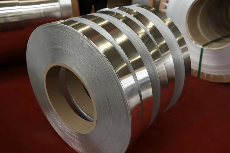
Aluminum foil is a critical base material for commercial vehicle motors, and its material properties determine the upper limit of motor performance.
Aluminum Foil Core Key Advantages
Weight Advantage (Critical):
- Aluminum density: 2.70 g/cm³
- Copper density: 8.96 g/cm³
- Aluminum weight is 30% that of copper
- Aluminum weight reduction is 70% for the same cross-sectional area
- Motor winding weight reduction is 50–60% under identical design conditions
- Vehicle weight reduction is 200–500 kg (commercial vehicle motors: 200–500 kW)
- Range extension is 5–10% (battery electric commercial vehicles)
Cost Advantage:
- Copper price (2024): CNY 60,000–70,000 per metric ton
- Aluminum price (2024): CNY 18,000–22,000 per metric ton
- Unit cost of aluminum is 30% that of copper
- Aluminum winding cost reduction: 30–50%
- Cost advantage becomes more pronounced after achieving economies of scale
Supply Stability:
- Aluminum is the most abundant metal in the Earth’s crust (8.13%).
- Copper accounts for only 0.007%.
- Aluminum supply is abundant, with minimal price volatility.
- China is the world’s largest aluminum producer.
- Aluminum supply chain stability is significantly superior to that of copper.
Performance Advantages:
- Heat dissipation: aluminum thermal conductivity 237 W/(m·K), copper thermal conductivity 401 W/(m·K)
- Although aluminum’s thermal conductivity is lower than copper’s, aluminum has a larger cross-sectional area
- Actual heat dissipation capability is comparable to copper
- Lower temperature rise (under identical design conditions)
Processing Advantages:
– Aluminum exhibits excellent ductility and machinability.
– Suitable for hairpin and rectangular (flat) wire windings.
– Low energy consumption during processing.
– Mature welding technologies (laser welding, friction stir welding).
Technical Disadvantages and Challenges of Aluminum Foil
Electrical Conductivity:
- Aluminum resistivity: 0.0283 Ω·mm²/m @20°C
- Copper resistivity: 0.0172 Ω·mm²/m @20°C
- Aluminum resistivity is 1.64 times that of copper
- Higher losses for the same length
- Larger cross-sectional area required for compensation
Mechanical Strength:
- Annealed aluminum tensile strength: 60–90 MPa
- Annealed copper tensile strength: 200–220 MPa
- Pure aluminum exhibits lower strength than copper
- Solution: Alloying (3003, 5052, 6061)
Creep Issue:
- Aluminum exhibits pronounced creep at elevated temperatures.
- Long-term use may result in relaxation.
- Solution: H-temper material + insulation coating + pre-tension design
Joining Process:
- Aluminum is prone to oxidation (Al₂O₃).
- The surface oxide layer affects soldering.
- Special welding processes are required (ultrasonic welding, laser welding, friction stir welding).
- Connection resistance must be strictly controlled.
Corrosion Issues:
- Aluminum is susceptible to corrosion in acidic/alkaline environments.
- Electrochemical corrosion protection is required at aluminum–copper junctions.
- Insulation coating protection is required.
Engineering Comparison: Aluminum Foil vs Copper Foil
| Parameter | Aluminum Foil | Copper Foil | Commercial Vehicle Application |
|---|---|---|---|
| Density (g/cm³) | 2.70 | 8.96 | 70% weight reduction with aluminum |
| Resistivity (Ω·mm²/m) | 0.0283 | 0.0172 | Copper is 1.64× lower |
| Thermal Conductivity (W/(m·K)) | 237 | 401 | Copper superior, but larger aluminum cross-section compensates |
| Unit Price (2024) | CNY 20,000/ton | CNY 65,000/ton | Aluminum 70% lower |
| Cross-Sectional Area Ratio for Equivalent Performance | 1.64 | 1.00 | Aluminum requires 1.64× cross-sectional area |
| Weight Ratio for Equivalent Performance | 0.50 | 1.00 | 50% weight reduction with aluminum |
| Oxidation Resistance | Poor | Good | Aluminum requires coating protection |
| Welding Process | Complex | Mature | Aluminum requires specialized process |
| Resource Availability | Abundant | Constrained | Aluminum supply stable |
Aluminum Foil Specifications and Material Selection
The aluminum foil specification system for commercial vehicle motors covers alloy grades, tempers, dimensions, and insulation.
Common Aluminum Alloy Grades
Pure Aluminum Series (1XXX Series):
- 1050A: Aluminum content 99.5%, conductivity 61% IACS
- 1060: Aluminum content 99.6%, conductivity 62% IACS
- 1070: Aluminum content 99.7%, conductivity 63% IACS
- 1235: Aluminum content 99.35%, conductivity 60% IACS
- 1A85: Aluminum content 99.85%, high purity
- 1A90: Aluminum content 99.90%, high purity
- 1A95: Aluminum content 99.95%, ultra-high purity
Aluminum–Manganese Alloys (3XXX Series):
- 3003: Al–Mn alloy with medium strength
- 3A21 (former designation LF21): Commonly used Al–Mn alloy
- Strength increased by 20–30% compared to pure aluminum
- Suitable for applications requiring higher mechanical strength
Aluminum–Magnesium Series (5XXX Series):
- 5052: Al-Mg alloy with high strength
- 5A02 (former designation LF2): Commonly used Al-Mg alloy
- 5A05: Al-Mg alloy with higher strength
- Suitable for high-strength applications
Al–Mg–Si series (6xxx series):
- 6061: Al-Mg-Si alloy, heat-treatable
- 6063: Al-Mg-Si alloy, excellent extrudability
- High strength, suitable for structural components
- Rarely used for motor windings
Aluminum–Iron–Silicon Series (8XXX Series):
- 8011: Al–Fe–Si alloy with high strength
- 8A06 (former designation LF6): Commonly used alloy
- Suitable for foil applications
Aluminum Foil Temper
Annealed (O) Temper:
- Tensile strength: 60–90 MPa
- Elongation: 25–35%
- Suitable for winding and forming
- Mainstream status in commercial vehicle motors
H temper (strain-hardened):
- H14: ½ Hard
- Tensile strength: 90–110 MPa
- Elongation: 8–12%
- H16: ¾ Hard
- Tensile strength: 110–130 MPa
- Elongation: 5–8%
- H18: Full Hard
- Tensile strength: 130–160 MPa
- Elongation: 3–5%
- H22: ¼ Hard (Annealed + Work-hardened)
- H24: ½ Hard (Annealed + Work-hardened)
T temper (heat treatment):
- T6: Solution heat treatment + artificial aging
- Highest strength (6061-T6: 310 MPa)
- Rarely used for motor windings
Aluminum Foil Dimensional Specifications
Thickness:
- Ultra-thin aluminum foil: 0.005–0.020 mm (not used for motors)
- Thin aluminum foil: 0.020–0.100 mm
- Standard aluminum foil: 0.10–0.50 mm
- Medium-thick aluminum foil: 0.50–2.0 mm
- Thick aluminum foil: 2.0–6.0 mm
- Commonly used for commercial vehicle motors: 0.30–3.0 mm
Width:
- Narrow aluminum foil: 20–100 mm
- Medium-width aluminum foil: 100–500 mm
- Wide aluminum foil: 500–1500 mm
- Commonly used for commercial vehicle motors: 50–300 mm (hairpin winding)
- Large motors: 300–800 mm
Length:
- Coils: 100–5000 m
- Cut lengths: 1–100 m
- Commercial vehicle motors: typically supplied in cut lengths
Shape:
- Rectangular: standard motor winding
- Trapezoidal: special slot shape
- Custom-shaped: custom geometry
- Hairpin: modern mainstream
- Rectangular busbar replacement: direct busbar substitution
Aluminum Foil Technical Specifications
| Grade | Temper | Thickness (mm) | Width (mm) | Resistivity (μΩ·m) | Tensile Strength (MPa) | Elongation (%) |
|---|---|---|---|---|---|---|
| 1060 | O | 0.30–3.0 | 50–300 | ≤0.0283 | 60–95 | 25–30 |
| 1050A | O | 0.30–3.0 | 50–300 | ≤0.0283 | 65–95 | 25–30 |
| 1235 | O | 0.30–2.0 | 50–300 | ≤0.0283 | 70–100 | 20–25 |
| 3003 | O | 0.30–2.5 | 50–300 | ≤0.0340 | 95–130 | 20–25 |
| 3A21 | O | 0.30–2.5 | 50–300 | ≤0.0340 | 95–130 | 20–25 |
| 5052 | O | 0.30–2.0 | 50–300 | ≤0.0350 | 170–220 | 20–25 |
| 5A02 | O | 0.30–2.0 | 50–300 | ≤0.0350 | 170–220 | 20–25 |
| 8011 | O | 0.10–1.0 | 50–300 | ≤0.0340 | 80–110 | 20–25 |
| 1060 | H18 | 0.10–1.0 | 50–200 | ≤0.0283 | 130–160 | 3–5 |
| 3003 | H14 | 0.30–1.5 | 50–200 | ≤0.0340 | 130–160 | 8–12 |
Aluminum Foil Surface Treatment
Bare aluminum foil:
- Ready for direct use
- Suitable for subsequent processing
- Storage requires oxidation protection
Coated Aluminum Foil:
– Insulation coating (AIW)
– Suitable for enamelled aluminium wire
– Class H (180 °C)
– Class C (220 °C)
Passivation Treatment:
- Chemical passivation film
- Prevents oxidation during storage
- Does not affect soldering (to be removed prior to soldering)
Coating Treatment:
- Nickel (Ni) plating
- Tin (Sn) plating
- Copper (Cu) plating
- Improved solderability
- Increased cost
Aluminum Foil Manufacturing Process
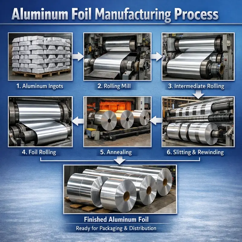
The manufacturing process of aluminum foil for commercial vehicle motors involves critical operations including melting and casting, rolling, annealing, and insulation treatment.
Aluminum Foil Manufacturing Process
Step 1: Melting and Casting
- Raw material: Electrolytic aluminum melt (99.7%+) or aluminum ingots for remelting
- Alloying: Addition of Mn, Mg, Si, Fe, and other elements
- Refining: Degassing and slag removal
- Casting: Semi-continuous casting (DC casting)
- Ingot dimensions: Thickness 200–600 mm
Step 2: Hot Rolling
- Heating temperature: 400–550 °C
- Rolling thickness: 6–30 mm
- Thickness after hot rolling: 2–8 mm
- Surface treatment: Oxide layer removal
Step 3: Cold Rolling:
- Multiple cold rolling (intermediate annealing + cold rolling cycles)
- Thickness reduced progressively from 2–8 mm to 0.10–3.0 mm
- Thickness tolerance: ±0.005–0.020 mm
- Surface roughness: Ra 0.4–1.6 μm
Step 4: Annealing
- Intermediate annealing: 350–400 °C
- Final annealing: 250–350 °C (O temper)
- Annealing equipment: Continuous annealing furnace, bell annealing furnace
- Post-annealing properties: Tensile strength, elongation
Step 5: Final Rolling:
– Thickness accuracy: ±0.002–0.005 mm
– Surface finish: Bright, matte
– Strip flatness: < 5 I-units
Step 6: Slitting
- Slitting width: according to customer requirements
- Winding: continuous winding
- Packaging: moisture-proof and oxidation-resistant
Aluminum Foil Enamel Coating Manufacturing Process
Step 1: Pretreatment:
- Degreasing: removal of oil and grease
- Pickling: removal of oxide layer
- Rinsing: removal of residual acid
Step 2: Primer Coating
- Coating materials: Polyester, polyester-imide, polyamide-imide
- Coating methods: Felt coating, roll coating
- Coating thickness: 0.020–0.050 mm (single-layer)
- Baking: 250–350 °C
Step 3: Topcoat Application
- Coating material: Polyamide-imide (AIW)
- Multi-layer coating (3–6 layers)
- Total coating thickness: 0.030–0.080 mm
- Coating grade: Grade 1 / 2 / 3
Step 4: Curing
- Baking temperature: 300–400 °C
- Baking time: Step-curing
- Enamel film properties: Adhesion, dielectric breakdown voltage, thermal shock resistance
Step 5: In-line Inspection:
- Film continuity (pinhole detection)
- Film thickness (online thickness measurement)
- Dielectric breakdown voltage (spot inspection)
Aluminum Foil Quality Control
Thickness Control:
- In-line X-ray thickness gauge
- Thickness tolerance: ±2–5% (depending on specification)
- Automatic gauge control (AGC)
Width Control:
- Online CCD width measurement
- Width tolerance: ±0.5–1.0 mm
- Automatic width control (AWC)
Flatness Control:
- Strip flatness inspection
- Roll profile adjustment
- Strip flatness grade: < 10 I-units
Surface Quality:
- Surface finish inspection
- Surface defect inspection
- 100% surface inspection or sampling inspection
Performance Testing:
- Resistivity: Four-point probe method
- Tensile strength: Universal testing machine
- Elongation: Tensile test
- Enamel coating: Dielectric breakdown voltage, adhesion
Aluminum Foil Insulation System
The insulation system of aluminum foil for commercial vehicle motors determines motor reliability and service life.
Enamel Insulation System
Insulation Type:
- Polyester (PEW): 130 °C (Class B)
- Polyester-imide (EIW): 155 °C (Class F)
- Polyamide-imide (AIW): 220 °C (Class C)
- Polyimide (PIW): 240 °C
- Epoxy (EP): Excellent chemical resistance
Insulation Class:
- Grade 0: 0.020–0.030 mm (thinnest)
- Grade 1: 0.030–0.050 mm
- Grade 2: 0.050–0.080 mm (standard)
- Grade 3: 0.080–0.110 mm (thickest)
Insulation Film Performance Requirements:
- Dielectric breakdown voltage: ≥5 kV (enamel coating thickness 0.050 mm)
- Adhesion: ≥3B (cross-cut test)
- Thermal shock resistance: no cracking after baking at ≥200 °C
- Chemical resistance: resistant to oil, acids, and alkalis
- Thermal class: Class H (180 °C), Class C (220 °C)
Composite Insulation System
Enamel + Glass Fiber (Glass-Fiber Covered):
- Base enamel coating: 0.030–0.050 mm
- Glass fiber braid layer: 0.10–0.30 mm
- Impregnated with varnish
- Dielectric breakdown voltage: ≥10 kV
- Thermal class: Class H (180 °C)
- Suitable for high-voltage motors
Enamel + Paper Covering
- Base enamel coating: 0.020–0.050 mm
- Paper wrapping layer: 0.20–0.50 mm (cable paper)
- Impregnated with insulating varnish
- Dielectric breakdown voltage: ≥15 kV
- Thermal class: Class A (105 °C)
- Suitable for oil-immersed transformers (rarely used in motors)
Insulation Coating + Polyimide Film (PI Film):
- Base enamel layer: 0.020–0.040 mm
- Polyimide (PI) film: 0.025–0.050 mm
- Composite structure
- Dielectric breakdown voltage: ≥10 kV
- Thermal class: Class H (180 °C) + 200 °C
- Suitable for high-end motors
Insulation Film + Mica
- Base enamel coating
- Mica tape wrapping
- Vacuum pressure impregnation (VPI)
- Breakdown voltage: ≥20 kV
- Thermal class: Class H or higher
- Suitable for large high-voltage motors
Slot Insulation and Phase-to-Phase Insulation
Slot Insulation:
- Slot insulation paper (DMD, NMN, NHN)
- Slot wedges (epoxy, fiberglass)
- Slot bottom spacers
- Slot opening protection
Phase Insulation:
- Inter-phase insulation (DMD, NMN)
- End winding tie-down
- Phase separation within slots
Impregnation Process:
- Vacuum Pressure Impregnation (VPI)
- Conventional impregnation
- Dip and drain, drip impregnation
- Impregnating varnishes: epoxy, modified epoxy, polyester
Aluminum Foil Stator Winding
The stator winding of commercial vehicle motors represents the primary application scenario for aluminum foil.
Hairpin Winding
Hairpin Winding Structure:
- Multiple rectangular aluminum wires pre-bent into U-shape (hairpin shape)
- Inserted into stator slots
- End twisting and welding
- Forming a complete armature winding
- The mainstream solution for commercial vehicle motors
Hairpin Winding Advantages:
- High slot fill factor: 65–75% (45–55% for round wire windings)
- 15–25% increase in power density
- Excellent heat dissipation (large end turns, good inter-turn contact)
- Suitable for automated production
- High consistency
- Suitable for high-power motors (100 kW and above)
Hairpin Winding Challenges:
- Complex manufacturing process
- High requirements for welding quality
- End-turn height issues
- High investment cost
- Requires hairpin-specific equipment
Hairpin Aluminum Foil Specifications:
- Typical thickness: 1.0–3.0 mm
- Typical width: 3–8 mm
- Cross-sectional area: 3–24 mm²
- Enamel coating: Grade 1–2
- Alloy designations: 1060-O, 3A21-O, 6101-T6
Hairpin Winding Application Case Study:
- BYD e-Platform: Battery-electric heavy-duty and light-duty trucks
- Tesla Semi: Battery-electric heavy-duty truck
- GM Ultium: Commercial vehicle platform
- Volvo: Battery-electric heavy-duty truck
- Daimler eActros: Battery-electric heavy-duty truck
Flat Wire Winding
Rectangular Wire Winding Structure:
– Direct winding with rectangular aluminum wire
– Suitable for distributed windings
– Suitable for concentrated windings
– High degree of automation
Rectangular Wire Winding Specifications:
- Thickness: 1.0–5.0 mm
- Width: 2–15 mm
- Cross-sectional area: 2–75 mm²
- Enamel coating: Grade 1–2
Concentrated Windings vs. Distributed Windings
Concentrated Winding:
- Few slots (6–12 slots)
- Short winding pitch
- Suitable for square-wave motors (SRM)
- Suitable for fractional-slot motors
- Aluminum foil applications: round aluminum wire, rectangular aluminum wire
Distributed Winding:
- High number of slots (36–72 slots)
- Large winding pitch
- Suitable for sinusoidal-wave motors
- Suitable for PMSM and IM
- Aluminum foil applications: hairpin, rectangular wire
End Design and Manufacturing
End Structure:
- End twist
- End termination (welding)
- End tying
- End insulation
End Welding:
- Laser welding: mainstream
- Tungsten inert gas (TIG) welding: less common
- Ultrasonic welding (USW): for thin parts
- Friction stir welding (FSW): for large parts
- Resistance welding: early-stage
End Insulation:
- End insulation varnish
- End binding tape
- End insulation tubing
- End insulation box
Connection of Aluminum Foil Stator Windings
Aluminum–Aluminum Connection:
- Laser welding: mainstream solution
- Solder: Al–Si solder, Al–Cu solder
- Welding temperature: 580–620 °C
- Weld strength: ≥80 % of base material
Aluminum–Copper Connections:
- Dissimilar metal welding
- Laser welding: feasible
- Friction welding: feasible
- Solder: special formulation
- Application: electrical terminal lead-out
Terminal Lead-Out:
- Copper terminal–aluminum wire connection
- Cold crimping + laser welding
- Bolted connection (power terminals)
- Nickel/tin plating to improve connectivity
Aluminum Foil Rotor Winding
Aluminum foil/aluminum castings are used in the rotor winding of commercial vehicle motors in certain applications.
Cast Aluminum Rotor
Cast aluminum rotor construction:
- Asynchronous motor rotor
- Squirrel-cage rotor
- Aluminum die-cast into rotor slots
- End ring connection
- Integral die-cast fan blades
Advantages of Cast Aluminum Rotors:
- Low cost
- High manufacturing efficiency
- Reliable construction
- Suitable for mass production
- Suitable for medium- and large-sized motors
Cast Aluminum Rotor Applications:
- Induction Motors (IM)
- Pure Electric Light-Duty Truck Traction Motors
- Partial Pure Electric Heavy-Duty Truck Auxiliary Motors
- Mining Motors
Cast aluminum material:
- Pure aluminum
- Al–Si alloy (8–12% Si)
- Al–Mg alloy
- Alloy designations: A356, A380, ADC12
Aluminum Foil Application in Squirrel-Cage Rotors
Squirrel-Cage Rotor Aluminum Foil Specifications:
– Shape: rectangular, trapezoidal, round
– Thickness: 0.5–5.0 mm
– Width: 5–20 mm
– Length: 50–500 mm
Advantages of Aluminum Foil for Squirrel-Cage Rotors:
– Excellent consistency (vs. cast aluminum)
– Stable performance
– Suitable for high-precision motors
– Suitable for large rotors
Rotor of Permanent Magnet Synchronous Motor
Rotor Structure of Permanent Magnet Synchronous Motor (PMSM):
- Permanent magnet (NdFeB)
- Rotor core
- End plate
- Balance weight
- Typically un-wound (permanent magnet excitation)
Application of Aluminum Foil in PMSM Rotors:
- End ring: lightweight design
- Balance weight: weight reduction
- Sleeve: support
- Reduced aluminum foil usage
Typical Working Conditions of Commercial Vehicle Motor
The actual operating conditions of commercial vehicle motors are significantly more complex than those of passenger vehicle motors, imposing higher reliability requirements on aluminum foil.
Operating Conditions Characteristics
Frequent start-stop cycles:
- Urban bus: 200–500 start-stop cycles per day
- Urban delivery light-duty truck: 100–300 cycles per day
- Start-stop acceleration current shock
- Temperature cycling shock
- Vibration shock
Long-Distance Continuous Operation Conditions:
- Heavy-duty truck trunk-line logistics: >1,000 km/day
- Long-distance passenger bus operation: 500–1,000 km/day
- Continuous high-torque output
- Continuous high-temperature operation
- Thermal dissipation challenges
Ramp-up operating condition:
- Heavy-duty trucks in mountainous areas: long-distance gradients of 6–8%
- Short-term gradients exceeding 15%
- Peak power output
- Rapid motor temperature rise
High-Speed Cruising:
- Highway: 90–120 km/h
- Stable high-speed operation
- High demand for air cooling and liquid cooling
Overload and Locked-Rotor Conditions:
- Short-time overload: 2–3 times rated
- Locked-rotor protection
- Instantaneous current surge
Impact of Operating Conditions on Aluminum Foil
Temperature Cycling Effect:
– Thermal cycling cycles per year for commercial vehicle motors: >5000
– Enamel film fatigue
– Enamel film cracking
– Coefficient of thermal expansion mismatch between copper and aluminum
– Winding loosening
Vibration Effects:
- Road surface excitation: 5–50 Hz, 1–10 g
- Engine vibration: 50–200 Hz
- End-winding vibration fatigue
- Enamel coating wear
- Winding loosening
Current surge impact:
- Frequent start-stop current surges
- Short-circuit current: 10–15 times rated current
- Electromagnetic force: proportional to the square of current
- Winding deformation
- Insulation wear
Chemical Environment Impact:
- Lubricants
- Coolants (ethylene glycol)
- Road salts
- Acid rain
- Corrosion challenges
Operating Conditions and Design Requirements for Aluminum Foil
High-Reliability Design:
- Film thickness: Grade 2–3
- End bundling: High-strength
- Slot wedges: High-strength
- Impregnation: VPI
- Leads: Double insulation
Thermal Management Design:
- Liquid cooling (direct oil cooling, water cooling)
- High-efficiency heat dissipation
- Winding temperature monitoring
- Temperature sensors
- Cooling optimization
Vibration-Resistant Design:
- Enhanced end-winding tie-down
- Optimized slot wedge design
- Vibration-damping design
- Vibration testing verification
Aluminum Foil Selection Decision
Selection of aluminum foil for commercial vehicle motors requires comprehensive consideration of multiple factors, including electrical, mechanical, thermal, and cost-related aspects.
Selection Decision Tree
Decision 1: Motor Type:
- PMSM (Permanent Magnet Synchronous Motor): Mainstream all-electric commercial vehicles
- Recommended aluminum foil: Hairpin winding aluminum wire
- Alloy designation: 1060-O, 3A21-O
- Enamel coating: Class H (180 °C)
- IM (Induction Motor): Some commercial vehicles
- Recommended aluminum foil: Cast aluminum rotor
- Alloy designation: A356, A380
- Enamel coating: Class B (130 °C)
- SRM (Switched Reluctance Motor): Some commercial vehicles
- Recommended aluminum foil: Concentrated winding
- Alloy designation: 1060-O
- Enamel coating: Class F (155 °C)
Decision 2: Power Rating
- Below 100 kW: Light-duty trucks, special-purpose vehicles
- Aluminum foil thickness: 1.0–2.0 mm
- Insulation coating: Grade 2
- Slot fill factor: 50–60%
- 100–300 kW: Medium-duty trucks, buses
- Aluminum foil thickness: 1.5–3.0 mm
- Insulation coating: Grade 2–3
- Slot fill factor: 60–70%
- 300–500 kW: Heavy-duty trucks
- Aluminum foil thickness: 2.0–4.0 mm
- Insulation coating: Grade 3
- Slot fill factor: 70–75%
- Above 500 kW: Mining equipment, extra-large applications
- Aluminum foil thickness: 3.0–5.0 mm
- Insulation coating: Grade 3 + mica
- Slot fill factor: ≥75%
Decision 3: Voltage Class
- 400 V system:
- Enamel coating: Grade 1–2
- Phase-to-phase insulation: Standard
- Slot insulation: DMD
- 600 V system:
- Enamel coating: Grade 2
- Phase-to-phase insulation: Enhanced
- Slot insulation: NMN
- 800 V system:
- Enamel coating: Grade 2–3
- Phase-to-phase insulation: High-grade
- Slot insulation: NHN + PI film
- 1000 V+ system:
- Enamel coating: Grade 3
- Phase-to-phase insulation: Highest-grade
- Slot insulation: PI + mica
Decision 4: Lifetime Requirement:
- 8 years / 1,500,000 km:
- Insulation coating: Class H (180 °C)
- Impregnation: Standard VPI
- 10 years / 2,000,000 km:
- Insulation coating: Class H (180 °C) + Polyimide (PI) film
- Impregnation: High-grade VPI
- 15 years / 3,000,000 km:
- Insulation coating: Class C (220 °C)
- Impregnation: Highest-grade VPI
- Reinforced end-winding tie-down
Decision 5: Cost Budget:
- Economy grade: pure aluminum, O temper, Grade 1
- Standard grade: aluminum alloy, O temper, Grade 2
- Premium grade: alloyed, H temper, Grade 3
Aluminum Foil Selection Cross-Reference Table
Cross-Sectional Area Equivalence: Copper Foil vs. Aluminum Foil
| Copper Cross-Sectional Area (mm²) | Equivalent Aluminum Cross-Sectional Area (mm²) | Aluminum Thickness (mm) × Width (mm) |
|---|---|---|
| 5 | 8.2 | 1.0 × 8.2 or 2.0 × 4.1 |
| 10 | 16.4 | 2.0 × 8.2 or 1.0 × 16.4 |
| 15 | 24.6 | 2.0 × 12.3 or 3.0 × 8.2 |
| 20 | 32.8 | 2.5 × 13.1 or 4.0 × 8.2 |
| 30 | 49.2 | 3.0 × 16.4 |
| 50 | 82.0 | 4.0 × 20.5 |
Weight Comparison: Aluminum Foil vs. Copper Foil
| Cross-sectional Area (mm²) | Copper Weight (kg/m) | Aluminum Weight (kg/m) | Weight Reduction Ratio |
|---|---|---|---|
| 10 | 0.0896 | 0.0270 | 70% |
| 20 | 0.1792 | 0.0540 | 70% |
| 30 | 0.2688 | 0.0810 | 70% |
| 50 | 0.4480 | 0.1350 | 70% |
| 100 | 0.8960 | 0.2700 | 70% |
Aluminum Foil Grade Selection:
- Winding forming: 1060-O, 1050A-O
- High strength requirement: 3003-O, 3A21-O
- Ultra-high strength: 5052-O, 5A02-O
- High heat dissipation requirement: 1060-O, 1235-O
- High welding requirement: 1060-O, 3A21-O
Typical Application Cases of Commercial Vehicle Motor
Case 1: Drive Motor for Battery Electric Heavy-Duty Trucks
Vehicle Model: 49-ton Battery Electric Heavy-Duty Truck
Motor Parameters:
- Motor type: Permanent Magnet Synchronous Motor (PMSM)
- Peak power: 500 kW
- Rated power: 250 kW
- Peak torque: 3500 N·m
- Rated torque: 1500 N·m
- Maximum speed: 3500 rpm
- Voltage class: 800 V
- Weight: 350 kg
Aluminum Foil Applications:
- Winding type: Hairpin winding
- Aluminum foil grade: 1060-O
- Aluminum foil dimensions: 2.5 mm × 8 mm
- Aluminum foil consumption per motor: approx. 35 kg
- Insulation coating: AIW Grade 2 (220 °C)
- End-winding welding: Laser welding
- Slot fill factor: 72 %
- Insulation system: Class H + VPI
Performance Comparison (vs. copper windings):
- Weight: Reduced from 480 kg to 350 kg (27% weight reduction)
- Cost: Reduced by 35%
- Efficiency: Peak efficiency of 96.8% (comparable to copper)
- Thermal management: Temperature rise reduced by 5–8 °C
- Range: Increased by 5–8%
Case 2: Drive Motor for Battery Electric Buses
Vehicle Model: 12-meter fully electric city bus
Motor Parameters:
- Motor type: Permanent Magnet Synchronous Motor (PMSM)
- Peak power: 350 kW
- Rated power: 200 kW
- Peak torque: 2800 N·m
- Voltage class: 600 V
- Weight: 280 kg
Aluminum Foil Applications:
- Winding type: Hairpin winding
- Aluminum foil grade: 1060-O
- Aluminum foil dimensions: 2.0 mm × 6 mm
- Aluminum foil consumption per motor: approx. 28 kg
- Insulation coating: AIW Grade 2
- End-winding welding: Laser welding
- Slot fill factor: 70%
Performance Advantages:
- Weight: reduced from 380 kg to 280 kg (26% weight reduction)
- Vehicle weight reduction: 100 kg
- Range increase: 4–6%
- Improved starting acceleration performance
Case 3: Drive Motor for Battery Electric Light-Duty Truck
Vehicle Model: 4.5-ton Battery Electric Logistics Light-duty Truck
Motor Parameters:
- Motor type: Permanent Magnet Synchronous Motor (PMSM)
- Peak power: 160 kW
- Rated power: 80 kW
- Peak torque: 500 N·m
- Voltage class: 400 V
- Weight: 85 kg
Aluminum Foil Applications:
- Winding type: Flat wire winding
- Aluminum foil grade: 1060-O
- Aluminum foil dimensions: 1.2 mm × 4 mm
- Aluminum foil consumption per motor: approx. 8 kg
- Enamel coating: PEW Grade 2 (Class B)
- End connection: Laser welding
- Slot fill factor: 60%
Performance Advantages:
– 40% cost reduction
– 28% weight reduction
– Suitable for high-volume production
Case 4: Fuel Cell Bus Traction Motor
Vehicle model: 12-meter fuel cell electric vehicle (FCEV)
Motor Parameters:
- Motor type: Permanent Magnet Synchronous Motor (PMSM)
- Peak power: 300 kW
- Rated power: 150 kW
- Voltage class: 600 V
- Weight: 240 kg
Aluminum Foil Applications:
- Winding type: Hairpin winding
- Aluminum foil grade: 1060-O
- Aluminum foil dimensions: 2.0 mm × 6 mm
- Insulation coating: Class C (220 °C)
- High-reliability insulation
Special Requirements:
– Long service life (15 years)
– High reliability
– Wide operating temperature range
– High humidity resistance
Case 5: Mining Motor Drive Motor
Vehicle Model: 100-ton Battery Electric Mining Dump Truck
Motor Parameters:
- Motor type: Permanent Magnet Synchronous Motor (PMSM)
- Peak power: 800 kW
- Rated power: 500 kW
- Peak torque: 8000 N·m
- Voltage class: 800 V
- Weight: 800 kg
Aluminum Foil Applications:
- Winding type: Hairpin winding
- Aluminum foil grade: 3A21-O (high-strength)
- Aluminum foil dimensions: 3.0 mm × 10 mm
- Insulation coating: AIW Grade 3
- Reinforced end-tie binding
- Enhanced insulation system
Special Requirements:
- Extreme operating conditions (heavy load, vibration, dust)
- Impact resistance
- Long service life
- Easy maintenance
Aluminum Foil Failure Modes and Quality Control
Common Failure Modes
Failure 1: Insulation Breakdown:
- Cause: Insulation film damage, pinholes
- Phenomenon: Phase-to-phase short circuit, ground fault
- Detection: Dielectric withstand voltage test
- Prevention: Upgrade insulation film class, strengthen quality inspection
Failure 2: End Weld Cracking
- Cause: Welding quality, vibration
- Phenomenon: Increased connection resistance, heating
- Detection: X-ray, ultrasonic testing
- Prevention: Optimize welding process, reinforce end bundling
Failure 3: Winding Overheating:
- Cause: Inadequate heat dissipation, overload
- Phenomenon: Enamel coating burnout, winding deformation
- Detection: Temperature monitoring
- Prevention: Optimize heat dissipation design, select appropriate wire specifications
Failure 4: Aluminum Foil Corrosion
- Cause: Moisture, chemical corrosion
- Phenomenon: Increased connection resistance, breakage
- Detection: Visual inspection, resistance measurement
- Prevention: Sealed design, corrosion-resistant coating
Failure 5: End Fatigue:
- Cause: Vibration, thermal cycling
- Phenomenon: End breakage
- Detection: Vibration testing
- Prevention: Reinforced end tying, material upgrade
Failure 6: Looseness in Slot:
- Cause: Vibration, thermal expansion
- Phenomenon: Insulation wear within the slot
- Detection: Impedance testing
- Prevention: Slot wedge optimization, impregnation reinforcement
Failure 7: Terminal Corrosion
- Cause: Electrochemical corrosion (aluminum–copper connection)
- Phenomenon: Terminal heating and burnout
- Detection: Infrared thermography
- Prevention: Plating treatment, sealing
Failure 8: Turn-to-Turn Short Circuit:
- Cause: Insulation film damage, vibration
- Phenomenon: Abnormal current, vibration
- Detection: Turn-to-turn test
- Prevention: Insulation film reinforcement, winding process optimization
Quality Control System
Raw Material Quality Control:
- Aluminum foil grade, temper, and dimensions
- Chemical composition analysis
- Mechanical properties testing
- Resistivity testing
- Enamel coating performance testing
Process Quality Control:
– Hairpin forming accuracy
– Insertion process quality
– End-welding quality
– Impregnation process quality
– In-line inspection
Finished Product Quality Control:
- Visual inspection
- Electrical testing (dielectric withstand, insulation resistance, turn-to-turn)
- Vibration testing
- Temperature rise testing
- Noise testing
- Ingress protection rating testing
Quality Assurance System:
- ISO 9001
- IATF 16949 (Automotive)
- ISO 14001
- Customer Certification (OEM)
- Supplier Certification
Development Trends of Aluminum Foil for Commercial Vehicle Motor
Trend 1: High-Voltage Platforms
- 800 V platform adoption
- 1000 V platform (for certain vehicle models)
- 1200 V platform (future)
- Enhanced aluminum foil insulation class
- Increased enamel coating thickness
- Higher dielectric breakdown voltage requirements
Trend 2: Higher Power Density
- Single-motor power exceeding 1000 kW
- Power density > 10 kW/kg
- Slot fill factor ≥ 75%
- Increased aluminum foil cross-sectional area
- Compact end-winding design
- Direct oil cooling / direct water cooling
Trend 3: New Aluminum Alloys
- 6XXX series aluminum alloy
- High-strength aluminum alloy
- High-conductivity aluminum alloy
- Composite aluminum foil (aluminum–copper composite)
- Coated aluminum foil (anti-oxidation)
Trend 4: Automated Manufacturing
- Hairpin fully automatic production line
- End-winding robotic welding
- In-line inspection and rework
- Digital quality management
- Smart factory
Trend 5: Recycling and Reuse
- Aluminum recycling (95%+ recycling rate)
- Circular economy model
- Reduced material costs
- Compliance with ESG requirements
- Reduced carbon emissions
Trend 6: 800 V Platform Aluminum Foil
- 800 V platform poses insulation challenges
- Increased enamel coating thickness
- Elevated dielectric breakdown voltage requirements
- Upgraded aluminum foil insulation system
- Expansion of the premium aluminum foil market
Trend 7: New Insulation Materials
- Nano-insulation coating
- High-thermal-conductivity insulation material
- Self-healing insulation material
- Widespread adoption of polyimide (PI) film
- Mica tape upgrade
Trend 8: Smart Motor Manufacturing
- AI-based quality inspection
- Digital twin
- Online monitoring
- Predictive maintenance
- Full lifecycle management
Conclusion
Aluminum foil for commercial vehicle motors, a critical foundational material for the electrification of commercial vehicles, has become the core winding material for motors in battery electric heavy-duty trucks, battery electric buses, battery electric light-duty trucks, and fuel cell buses—offering significant advantages over traditional copper wire, including 50–60% weight reduction, 30–50% cost reduction, superior heat dissipation, and stable supply.
Key Considerations for Aluminum Foil Applications in Commercial Vehicle Motors:
- Understanding the characteristics of commercial vehicle motors: differences from passenger vehicle motors include heavy-duty operation, extended operating duration, high reliability, and long service life.
- Mastering aluminum foil material properties: balancing lightweight design, cost, electrical conductivity, and mechanical performance.
- Selecting appropriate aluminum foil grades: e.g., 1060-O, 3A21-O, 5052-O, 3003-O.
- Determining aluminum foil specifications: thickness, width, enamel coating class, and insulation system.
- Adopting hairpin winding technology: enabling high slot fill factor and high power density.
- Emphasizing welding processes: laser welding, end-turn connections, and reliability.
- Enhancing the insulation system: H-class/C-class enamel coatings and vacuum pressure impregnation (VPI).
- Designing for typical operating conditions: heavy-duty loads, vibration, and thermal cycling.
- Implementing rigorous quality control: covering raw materials, in-process inspection, finished products, and reliability testing.
- Monitoring future trends: high-voltage systems, high power density, and novel materials.
Commercial vehicle motor engineers, designers, procurement personnel, and OEMs should systematically acquire expertise in aluminum foil applications for commercial vehicle motors—through structured learning (aluminum foil material systems, insulation systems, manufacturing processes, application case studies), supplier collaboration (aluminum foil producers, insulation material suppliers, motor manufacturers), quality control (incoming material inspection, in-process control, finished product testing), and technology tracking (new aluminum foils, novel processing techniques, emerging applications)—to provide core material support enabling large-scale, high-quality, and cost-effective electrification of commercial vehicles.