


Introduction
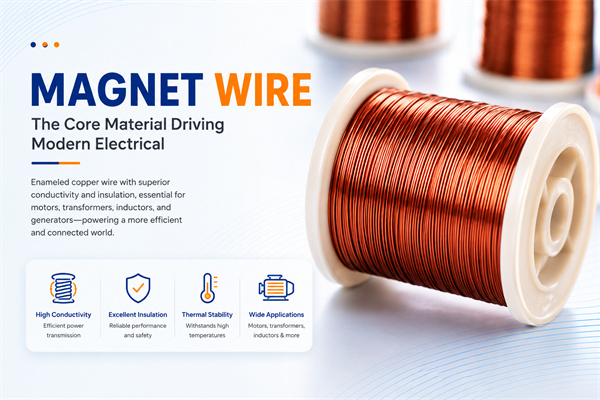
Magnet Wire for Transformer Coil Applications is one of the longest-established and most mature core engineering fields in the magnet wire (enameled wire) industry. As a critical component in power systems, electronic equipment, power supplies, and new-energy equipment, transformer performance—encompassing efficiency, reliability, and service life—is closely linked to the electrical, insulation, thermal, and mechanical properties of magnet wire. Magnet wire fulfills the essential functions of electromagnetic energy conversion and electrical isolation across diverse transformer types: from power transformers and distribution transformers in power systems, to high-frequency transformers and switch-mode power supply (SMPS) transformers in power electronics; from wind-power transformers and photovoltaic inverter transformers in new-energy applications, to traction transformers in rail transit systems; and from small power transformers in household appliances to isolation transformers in industrial control equipment.
From the perspective of transformer engineering practice, the engineering value of magnet wire in transformers manifests across multiple dimensions. Electrically, the conductor resistance of the magnet wire determines the transformer’s copper losses; the dielectric strength of the enamel coating determines the reliability of both main and turn-to-turn insulation of the winding; and the enamel coating thickness affects the window fill factor and transformer efficiency. Mechanically, the flexibility and tensile strength of the magnet wire determine the feasibility of winding processes, while the abrasion resistance of the enamel coating ensures insulation integrity during coil shaping and assembly. Thermally, the temperature rating of the magnet wire defines the upper limit of the transformer’s power density and its long-term operational lifetime. Chemically, the magnet wire’s resistance to chemical media determines compatibility with transformer oil impregnation processes and long-term reliability.
The engineering implications of magnet wire for transformer coil applications can be systematically elaborated from seven dimensions: transformer fundamentals and winding types, insulation coating systems and thermal classes, conductor materials, key performance requirements, losses and efficiency, applications in new energy and power electronics, and selection strategies. This article provides a systematic engineering reference for transformer manufacturers, transformer designers, power supply manufacturers, inductor manufacturers, and magnetic component procurement engineers.
Transformer Fundamentals and Winding Types
A transformer is a stationary electromagnetic device that achieves voltage transformation, current transformation, impedance transformation, and electrical isolation based on the principle of electromagnetic induction; understanding the fundamentals of transformers and winding types is a prerequisite for magnet wire selection.
Fundamental Principles of Transformers
A transformer consists of fundamental components including the core, windings, insulation system, tank or enclosure, and cooling system. The core provides a low-reluctance magnetic path. The windings, wound from magnet wire (enameled wire), carry current and enable electromagnetic induction. The insulation system provides electrical isolation between windings, between windings and core, and between windings and enclosure. The cooling system dissipates heat generated during transformer operation to ensure long-term stable performance.
The operating principle of a transformer is based on Faraday’s law of electromagnetic induction. An alternating current applied to the primary winding generates an alternating magnetic flux, which is conveyed through the core to the secondary winding, inducing an electromotive force (EMF) in the secondary winding proportional to the turns ratio between the primary and secondary windings. Voltage transformation is achieved via the turns ratio of the primary and secondary windings, while power transfer is accomplished via the current ratio between the primary and secondary windings.
Winding Types
Transformer windings are available in a wide variety of types, classified according to different criteria. By voltage level: low-voltage windings, medium-voltage windings, high-voltage windings, and extra-high-voltage windings. By function: main windings, auxiliary windings, electrostatic shield windings, tap-changing windings, and compensation windings. By structural configuration: cylindrical windings, disc windings, continuous windings, helical windings, foil windings, and Litz wire windings.
Cylindrical windings are constructed layer by layer using round-section enameled wire, featuring simple structure and ease of manufacturing; they are suitable for low-voltage and high-voltage windings of small- and medium-sized transformers. Disc windings consist of pancake-shaped units wound from rectangular (flat) wire or round wire, offering superior mechanical strength and excellent heat dissipation; they are suitable for high-voltage and medium-voltage windings of medium- and large-sized transformers. Helical windings are formed by parallel winding of multiple flat wires and are suitable for low-voltage, high-current transformers. Foil windings are fabricated from copper foil or aluminum foil, providing high space factor and excellent heat dissipation; they are suitable for low-voltage, high-current transformers. Litz wire windings comprise multiple fine enameled wires twisted together, minimizing skin effect losses, and are suitable for high-frequency transformers.
Relationship Between Windings and Magnet Wire
The relationship between transformer windings and magnet wire forms the foundation for magnet wire selection. The electromagnetic design of the winding determines the conductor material, conductor diameter, conductor cross-sectional shape, and insulation film type of the magnet wire. The insulation design of the winding determines the dielectric strength, insulation film thickness, and number of insulation film layers of the magnet wire. The process design of the winding determines the flexibility, tensile strength, insulation film abrasion resistance, and solderability of the magnet wire. The operating environment of the winding (oil-immersed, dry-type, high-frequency, high-voltage) determines the oil resistance, temperature rating, and chemical resistance of the magnet wire.
Enamel System and Thermal Class
The enamel system and thermal class system of magnet wire for transformers determine the transformer’s long-term operational capability under varying temperature conditions.
Primary Enamel Systems
The primary enamel systems for transformer magnet wire include polyester (PEW), polyurethane (UEW), modified polyester, polyester-imide (PEI), polyamide-imide (PAI), and polyimide (PI). Each enamel system possesses distinct performance characteristics and is suited to specific transformer applications.
Polyester enamel (PEW) offers low cost, good mechanical properties, and moderate dielectric properties, making it suitable for small- and medium-sized power transformers, distribution transformers, and household appliance transformers. Typical thermal class is Class 130.
Polyurethane enamel (UEW) offers outstanding advantages including solderability without prior stripping, low-temperature curing, and low dielectric loss, making it suitable for electronic transformers, high-frequency transformers, precision transformers, and switch-mode power supply (SMPS) transformers. Typical thermal classes range from Class 130 to Class 155.
Modified polyester enamel film is developed by incorporating modified monomers into standard polyester enamel, resulting in improved thermal stability and mechanical properties. It is suitable for control transformers and precision transformers. Typical thermal class: Class 155.
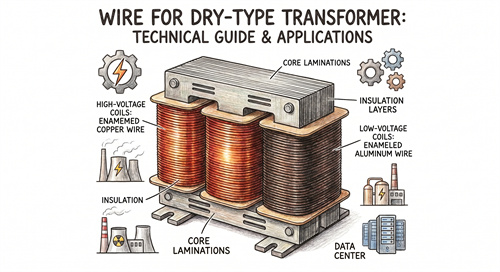
Polyester-imide (PEI) enamel film incorporates imide bonds into a polyester base, significantly enhancing thermal stability while offering superior dielectric and mechanical properties. It is suitable for dry-type transformers, high-voltage transformers, and traction transformers. Typical thermal class: Class 180.
Polyamide-imide (PAI) enamel coating offers superior thermal stability and dielectric strength, suitable for high-power-density transformers, new-energy-vehicle transformers, wind-power-generation transformers, and high-speed-rail traction transformers. Typical thermal class is Class 200.
Polyimide (PI) enamel exhibits exceptional thermal stability and dielectric strength, making it suitable for aerospace transformers and specialty high-temperature application transformers. Typical thermal classes range from Class 220 to Class 240.
Thermal Class Selection
The thermal class selection for magnet wire used in transformers must comprehensively consider the transformer’s power density, efficiency grade, operating temperature, cooling method, and expected service life. Oil-immersed power transformers typically employ enamel coatings rated Class 105 to Class 130. Dry-type transformers typically employ enamel coatings rated Class 155 to Class 180. High-frequency switching power supply transformers typically employ enamel coatings rated Class 180 to Class 200. New-energy vehicle power transformers typically employ enamel coatings rated Class 200 or higher. Wind-power generation transformers typically employ enamel coatings rated Class 180 to Class 200.
Enamel Coating Thickness Classes
The paint film thickness grade system for transformer magnet wire complies with the grading provisions of international and national standards including IEC 60317, NEMA MW 1000, and GB/T 6109. The paint film thickness grades primarily include Single (Grade 1), Heavy (Grade 2), and Triple Heavy (Grade 3). Single paint film is preferred for small transformers to improve the fill factor. Heavy or Triple Heavy paint film is preferred for high-voltage transformers and traction transformers to enhance dielectric strength and impact resistance.
Conductor Materials
The selection of conductor material for magnet wire used in transformers directly affects the transformer’s electrical performance, mechanical performance, thermal performance, weight, and cost.
Copper Conductor
Copper is the predominant conductor material for magnet wire used in transformers. With its low resistivity and among the highest electrical conductivity of all practical metals, copper also exhibits excellent machinability, making it the preferred conductor material for transformer windings. Transformer-grade copper magnet wire typically employs electrolytic tough pitch (ETP) copper as the conductor material. Conductor cross-sectional shapes include round wire, rectangular (flat) wire, and square wire. Round wire is suitable for multi-layer cylindrical windings in small- and medium-sized transformers. Rectangular (flat) wire is employed in disc-type and helical windings of medium- and large-sized transformers, offering high space factor and superior heat dissipation. Square wire is used for specialized transformer windings.
Aluminum Conductors
Aluminum is a lightweight conductor option for magnet wire used in transformers. Due to its abundant availability, lower cost compared to copper, and weight approximately one-third that of copper, aluminum is the preferred conductor material for lightweight design of large power transformers and distribution transformers. Aluminum magnet wire is widely applied in large power transformers, distribution transformers, and dry-type transformers. Windings using aluminum magnet wire typically employ aluminum rectangular wire or aluminum foil, and the winding process differs from that used for copper wire.
Copper-Clad Aluminum (CCA) Conductors
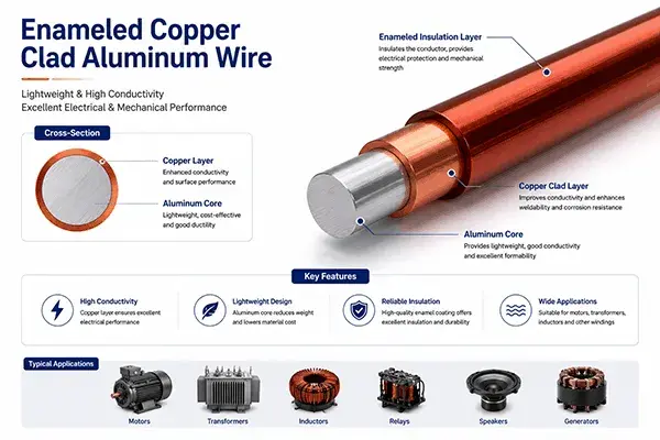
Electrical Copper Clad Aluminum (ECCA) is a novel conductor material for transformer magnet wire. ECCA magnet wire exhibits lower DC conductivity than pure copper magnet wire but achieves high-frequency conductivity comparable to that of pure copper magnet wire. The weight of ECCA magnet wire is significantly lower than that of pure copper magnet wire, and its cost lies between that of pure aluminum and pure copper. ECCA magnet wire offers application value in lightweight transformers, new-energy vehicle transformers, and high-frequency power electronic transformers.
Conductor Cross-Sectional Shape
The selection of conductor cross-sectional shapes for transformer magnet wire must comprehensively consider transformer capacity, voltage, current, winding structure, and insulation design. Round wire is suitable for multi-layer cylindrical windings in small- and medium-sized transformers, featuring simple winding processes. Rectangular (flat) wire is suitable for high-voltage and low-voltage windings in medium- and large-sized transformers, offering high fill factor and excellent heat dissipation performance. Litz wire is suitable for high-frequency transformers, exhibiting low skin-effect loss and low proximity-effect loss. Copper foil and aluminum foil are suitable for low-voltage, high-current transformers, providing compact winding structures and superior heat dissipation performance.
Key Performance Requirements
Key performance requirements for magnet wire used in transformers span multiple dimensions, including electrical properties, mechanical properties, thermal properties, chemical properties, and long-term reliability.
Electrical Performance Requirements
Electrical performance requirements for magnet wire used in transformers include conductivity, dielectric strength, film continuity, dielectric loss tangent, and DC voltage withstand.
Electrical conductivity directly affects transformer copper losses and efficiency. The direct-current (DC) resistance of magnet wire is determined by the conductor material, conductor cross-sectional area, and winding length. Precision and consistency of the conductor cross-sectional area influence electromagnetic design and performance of transformers. Large power transformers and new-energy vehicle transformers impose high requirements on magnet wire conductivity, necessitating high-purity oxygen-free copper conductors to minimize copper losses.
Dielectric strength is a critical parameter indicating the voltage stress resistance of magnet wire and determines its insulation reliability in transformer windings. High-voltage (HV) and extra-high-voltage (EHV) transformers impose extremely high requirements on the dielectric strength of magnet wire. Dielectric strength is influenced by enamel coating thickness, enamel coating uniformity, enamel coating quality, and conductor surface quality. The transformer’s longitudinal insulation (turn-to-turn insulation, layer-to-layer insulation, section-to-section insulation) and main insulation (winding-to-ground insulation, phase-to-phase insulation) impose distinct dielectric strength requirements on magnet wire.
Coating continuity is a comprehensive indicator of magnet wire manufacturing quality, reflecting the coating’s ability to provide continuous coverage over the conductor surface. Coating continuity defects can lead to dielectric breakdown failure of magnet wire under voltage stress and are one of the primary causes of transformer insulation failure.
Dielectric loss tangent (tan δ) is a critical parameter for magnet wire in high-frequency applications. High-frequency transformers and switch-mode power supply (SMPS) transformers impose stringent dielectric loss requirements on magnet wire. Low-dielectric-loss enamel coatings reduce insulation losses in high-frequency transformers, thereby improving transformer efficiency.
Mechanical Property Requirements
Mechanical property requirements for magnet wire used in transformers include tensile strength, elongation, flexibility, abrasion resistance, and impact resistance. During winding, coil shaping, and assembly, magnet wire is subjected to various mechanical stresses, including tension, bending, torsion, and friction.
Winding processes impose requirements on enameled wire regarding flexibility and tensile strength. Specialized winding machines are used for winding large transformers, subjecting the enameled wire to high winding tension. Winding of rectangular (flat) wire imposes requirements on the enameled wire’s bendability. Litz wire winding imposes requirements on the enameled wire’s abrasion resistance.
The coil shaping process imposes requirements on the flexibility and resistance to deformation of magnet wire. Mechanical performance requirements for magnet wire are particularly high during transformer winding end shaping, compaction, and binding.
Thermal Performance Requirements
Thermal performance requirements for magnet wire used in transformers include thermal shock, softening breakdown, temperature index, and thermal aging life. Transformers are subjected to thermal stress and cyclic temperature variations during long-term operation.
Thermal shock testing evaluates the integrity of the enamel coating on magnet wire under conditions of rapid temperature change. Rapid temperature changes occur during transformer startup, shutdown, overload, and short-circuit events; therefore, the magnet wire must exhibit excellent thermal shock performance.
The softening breakdown test evaluates the varnish film stability of magnet wire at elevated temperatures. The operating temperature of transformers under rated load, overload, or short-circuit conditions may exceed the varnish film softening temperature, leading to insulation failure.
Temperature index evaluates the maximum long-term operating temperature of magnet wire. The temperature index of transformer magnet wire must match the temperature class of the transformer’s insulation system.
Chemical Property Requirements
Chemical performance requirements for magnet wire used in transformers include oil resistance, hydrolysis resistance, and resistance to chemical media. Magnet wire for oil-immersed transformers is continuously immersed in transformer oil and must exhibit excellent oil resistance. Magnet wire for dry-type transformers is continuously exposed to ambient atmospheric conditions and must possess resistance to humid heat and oxidation.
Oil resistance is a critical performance parameter for magnet wire used in oil-immersed transformers. The enamel coating of the magnet wire must maintain stable performance under prolonged oil immersion, without failure modes such as dissolution, swelling, delamination, or powdering.
Magnet wire for new-energy vehicle transformers must exhibit resistance to ATF oil, coolant, and chemical media. Magnet wire for wind-power-generation transformers must exhibit resistance to salt spray, humidity, and ultraviolet radiation.
Long-term reliability requirements
Long-term reliability requirements for magnet wire used in transformers include thermal aging life, vibration resistance, and environmental resistance. Transformers are typically required to operate for 20 to 30 years, during which the magnet wire must maintain stable electrical, mechanical, and insulation properties.
Power transformer design life requirements exceed 30 years, demanding extremely high long-term reliability of magnet wire. Traction transformer design life requirements exceed 30 years and must withstand frequent start-up, shutdown, and overload surges. New energy vehicle transformer design life requirements exceed 15 years and must maintain long-term reliability under the harsh automotive operating environment.
Losses and Efficiency
Transformer efficiency is a core performance metric for transformers, and the performance of magnet wire directly affects the transformer’s efficiency class.
Mechanism of Enamelled Wire Impact on Transformer Losses
The impact of magnet wire on transformer losses is primarily reflected in three aspects: copper loss, additional loss, and insulation loss.
Copper loss is one of the primary sources of transformer losses, and its magnitude is determined by the conductor resistance of the magnet wire. The conductor material, conductor cross-sectional area, and winding length of the magnet wire directly affect the transformer’s copper loss. Engineering approaches to reduce copper loss include using conductor materials with higher electrical conductivity (e.g., oxygen-free copper), increasing the conductor cross-sectional area (to improve the fill factor), and shortening the winding length (through optimized electromagnetic design).
Additional losses include skin effect loss, proximity effect loss, and eddy current loss. Skin effect loss increases with operating frequency and is particularly significant in high-frequency transformers. Proximity effect loss becomes pronounced when multiple enameled wires are closely packed; therefore, winding design must optimize the arrangement of enameled wires to minimize proximity effect loss. Eddy current loss occurs primarily within the conductor of the enameled wire and in the core; using Litz wire or stranded wire effectively reduces eddy current loss in windings.
Insulation loss refers to the dielectric loss of magnet wire under high-frequency voltage, which increases significantly with rising frequency. Insulation loss is closely related to the dielectric loss tangent (tan δ) of the enamel coating. Insulation loss must be specially evaluated for high-frequency transformers.
Application of High-Efficiency Transformer Magnet Wire
High-efficiency transformers impose stringent performance requirements on magnet wire. Engineering practices for magnet wire used in high-efficiency transformers include employing oxygen-free copper conductors with higher electrical conductivity, utilizing magnet wire with larger cross-sectional areas to reduce current density, applying high-temperature-resistant enamel coatings to increase the upper limit of allowable current density, and applying low-dielectric-loss enamel coatings to minimize insulation losses.
New energy vehicle (NEV) power transformers impose extremely stringent efficiency requirements, typically demanding efficiency levels above 98%. Magnet wire applications for NEV power transformers include high-purity oxygen-free copper conductors, Class 200 high-temperature enamel coatings, Litz wire construction to reduce high-frequency losses, and low-dielectric-loss enamel coatings to minimize insulation losses.
Data center transformers and communication equipment transformers also require high efficiency, typically meeting the 80 PLUS Titanium or equivalent efficiency standards. Selection of magnet wire for data center transformers must comprehensively consider electrical conductivity, insulation performance, and long-term reliability.
Impact of Magnet Wire on Transformer Service Life
The impact of magnet wire on transformer service life is primarily reflected at two levels: insulation life and mechanical life.
Insulation service life is determined by the thermal aging life of the enamel coating. The thermal aging life of the enamel coating is closely related to the temperature index, operating temperature, and temperature cycling. Higher operating temperatures result in shorter thermal aging life of the enamel coating. Enamel coatings with higher temperature indices exhibit longer thermal aging life. The insulation service life of transformers is typically predicted and evaluated using the Arrhenius model.
Mechanical service life is determined by the mechanical stability of the enamel coating. The stability of the enamel coating under prolonged vibration, thermal cycling, and mechanical stress affects the mechanical service life of transformers. Enamel coatings for long-life transformers—such as traction transformers and wind-power generation transformers—must exhibit exceptional mechanical stability.
New Energy and Power Electronics Applications
New energy and power electronics applications represent an emerging market for transformer magnet wire, imposing new technical requirements on magnet wire.
New Energy Vehicle Transformers
New-energy vehicle transformers include on-board charger (OBC) transformers, DC-DC converter transformers, high-voltage bus transformers, and motor drive transformers. Requirements for magnet wire used in new-energy vehicle transformers focus on high efficiency, high power density, high temperature resistance, high-frequency performance, and high reliability.
The operating frequency of new-energy vehicle transformers typically ranges from tens of kilohertz to hundreds of kilohertz, imposing high requirements on the high-frequency performance of magnet wire. The operating temperature of new-energy vehicle transformers is generally high, necessitating high-temperature enamel coatings rated Class 180 to Class 200. Given the harsh service environment of new-energy vehicles, the magnet wire must exhibit resistance to vibration, impact, and thermal cycling.
Wind Power Generation Transformers
Wind power generation transformers include nacelle transformers, tower transformers, and substation transformers. Requirements for magnet wire used in wind power generation transformers focus on high weather resistance, high temperature resistance, high efficiency, and high reliability.
Wind power generation transformers operate outdoors for extended periods, subjected to harsh environmental conditions including high humidity, salt fog, temperature fluctuations, and ultraviolet (UV) radiation. Magnet wire must exhibit resistance to salt fog, moisture, and UV radiation. Due to the large unit power rating and long operational duration of wind power generation transformers, magnet wire is required to demonstrate exceptionally high long-term reliability.
Photovoltaic Inverter Transformers
Photovoltaic (PV) inverter transformers are one of the core components of photovoltaic power generation systems. Requirements for magnet wire used in PV inverter transformers focus on high efficiency, high-frequency performance, high-temperature resistance, and high power density.
Photovoltaic (PV) inverter transformers operate at high frequencies, and the high-frequency performance of magnet wire significantly affects inverter efficiency. PV inverters operate outdoors for extended periods, requiring magnet wire with weather resistance and thermal resistance. As the power density of PV inverters continues to increase, magnet wire must exhibit high thermal resistance and high insulation performance.
Rail Transit Traction Transformers
Rail transit traction transformers are core components of rail transit vehicles. Requirements for magnet wire used in rail transit traction transformers focus on high temperature resistance, high dielectric strength, high vibration resistance, and high long-term reliability.
The operating conditions of rail transit traction transformers are severe, requiring endurance against frequent start-ups, shutdowns, overloads, and short-circuit shocks. The magnet wire must exhibit high temperature resistance, high insulation performance, and high vibration resistance. Traction transformer design life requirements exceed 30 years, imposing extremely stringent long-term reliability requirements on the magnet wire.
Switch-Mode Power Supply (SMPS) Transformers
Switch-mode power supply (SMPS) transformers are one of the core components of switch-mode power supplies. SMPS transformers impose stringent requirements on magnet wire, focusing on high efficiency, high-frequency performance, low losses, and high power density.
The operating frequency of switch-mode power supply (SMPS) transformers typically ranges from tens of kilohertz to several megahertz, demanding high-frequency performance from magnet wire. SMPS transformers commonly employ Litz wire windings to reduce skin effect losses. As the power density of SMPS transformers continues to increase, magnet wire must exhibit high thermal endurance and superior insulation performance.
Selection Strategy
Selection of magnet wire for transformers must comprehensively consider transformer type, capacity, voltage, frequency, insulation class, efficiency requirements, environmental conditions, and service life requirements.
Selection by Transformer Type
Power transformers typically use Class 105 to Class 130 polyester enamel-coated round or rectangular wire, with copper or aluminum conductors. Distribution transformers typically use Class 130 polyester enamel-coated round or rectangular wire, with copper or aluminum conductors. Dry-type transformers typically use Class 155 to Class 180 enamel-coated wire, with copper conductors. Electronic transformers typically use Class 130 to Class 155 polyurethane enamel-coated round wire, with copper conductors. High-frequency switching power supply transformers typically use Class 180 to Class 200 enamel-coated Litz wire, with oxygen-free copper conductors. New energy vehicle transformers typically use Class 200 high-temperature enamel-coated Litz wire, with oxygen-free copper conductors.
Selection by Capacity and Voltage
Small-capacity low-voltage transformers (less than 1 kVA) typically employ fine-diameter round enameled wire with single-layer insulation. Medium- and small-capacity medium-voltage transformers (1–100 kVA) typically use medium-diameter round enameled wire or rectangular (flat) enameled wire with thickened insulation. Large-capacity high-voltage transformers (greater than 100 kVA) typically utilize coarse-diameter rectangular (flat) enameled wire with triple-thickened insulation. Extra-high-voltage transformers require specially designed enameled wire systems, including reinforced insulation and special insulation structures.
Selection by Frequency
Power frequency transformers (50/60 Hz) typically employ round or rectangular enameled wire. Medium-frequency transformers (hundreds to thousands of Hz) require consideration of the skin effect and may utilize stranded wire or Litz wire. High-frequency transformers (tens of kHz and above) commonly use Litz enameled wire to minimize skin effect and proximity effect losses. Radio-frequency transformers (several MHz and above) generally employ specially designed Litz wire or air-core windings.
Selection Based on Efficiency Requirements
High-efficiency transformers (IE3 and higher efficiency classes) require high-purity oxygen-free copper conductors, low-loss enamel coatings, and optimized winding designs. Ultra-high-efficiency transformers (IE4 and higher efficiency classes) require the optimal conductor materials, enamel coatings, winding structures, and material systems.
Selection by Environmental Conditions
Transformers for outdoor environments require weather-resistant enameled wire (UV-resistant, moisture-resistant, salt fog-resistant). Transformers for oil-immersed environments require oil-resistant enameled wire (transformer oil-resistant, hot oil-resistant). Transformers for high-humidity environments require humidity- and heat-resistant enameled wire (hydrolysis-resistant, moisture-resistant). Transformers for vibration-prone environments require enameled wire with high mechanical stability (high abrasion resistance, high vibration resistance).
Selection Based on Lifetime Requirements
Long-life transformers (service life exceeding 30 years) require magnet wire with Class 180 or higher insulation, high-quality enameled wire, and optimized winding design. Ultra-long-life transformers (nuclear power, special applications) require magnet wire with Class 200 or higher insulation and enameled wire with special quality assurance.
Conclusion
The engineering scope of Magnet Wire for Transformer Coil Applications encompasses seven core engineering dimensions: transformer fundamentals and winding types (basic transformer principles, winding types, and the relationship between windings and magnet wire); insulation film systems and thermal classes (e.g., polyester, polyurethane, polyester-imide, polyamide-imide, polyimide films; thermal classes from Class 105 to Class 240); conductor materials (copper, aluminum, copper-clad aluminum, and conductor cross-sectional geometry selection); key performance requirements (electrical, mechanical, thermal, chemical, and long-term reliability); losses and efficiency (mechanisms by which magnet wire influences transformer losses, application of high-efficiency transformer magnet wire, and impact of magnet wire on transformer service life); applications in new energy and power electronics (new-energy vehicles, wind power generation, photovoltaic inverters, rail transit, and switch-mode power supply transformers); and selection strategies (selection based on transformer type, capacity and voltage, frequency, efficiency, operating environment, and service life).
Magnet wire for transformers is the fundamental guarantee of transformer performance, efficiency, reliability, and service life. Selection of magnet wire must comprehensively consider multiple factors, including transformer type, capacity, voltage, frequency, insulation class, efficiency requirements, environmental conditions, and service life requirements. Significant differences exist in magnet wire requirements across various transformer application fields; therefore, selection must be tailored to the specific transformer type.
Magnet wire manufacturers shall continuously enhance product performance, deepen research on transformer applications, expand product specification portfolios, and improve quality assurance systems to supply transformer manufacturers with high-quality, high-performance, and highly reliable magnet wire products.
About the Author
Zhengzhou Lanpu Industrial Co., Ltd. is a source manufacturer of magnet wire with 30 years of export experience, operating a modern production base spanning 60 mu. The company specializes in manufacturing copper, aluminum, and aluminum-clad copper enameled round wire, flat wire, and square wire, covering the full range of thermal classes. Its products are certified to ISO 9001/14001/45001, UL, REACH, and RoHS standards and are exported to more than 50 countries.
Contact Information:
- 📧 Email: <office@cnlpzz.com>
- 📱 WhatsApp: 0086-19337889070
- 🌐 Website: <https://lpenamelwire.com/>