


How to Solder Aluminum Magnet Wire: Methods and Quality Control I. Metallurgical Challenges in Aluminum Welding
1.1 Alumina Film Barrier
The naturally formed alumina film (Al₂O₃) on the aluminum conductor surface is amorphous, electrically insulating, and chemically stable, with a thickness of approximately 2-10 nm at room temperature. This is the core obstacle preventing conventional tin-lead or lead-free solders from wetting the aluminum surface—because this oxide film is insoluble in rosin-based or no-clean fluxes at typical welding temperatures (240-400°C). Standard fluxes cannot remove the oxide film and must be handled through mechanical destruction, chemical dissolution, or bypassing the solid-state connection.
1.2 Thermal Conductivity Considerations
The thermal conductivity of pure aluminum is 237 W/(m·K), approximately 60% of that of copper (401 W/(m·K)), but still significantly higher than that of iron alloys used in transformer cores. During welding, this characteristic requires concentrated heat input at the joint interface to reach the wetting temperature in a very short time (especially in resistance welding and laser welding processes, with cycles measured in milliseconds).
1.3 Enamelled Aluminum Wire Contamination Issues
For enameled aluminum wire, the insulation enamelled coating must be completely removed before welding—residual enamelled coating decomposes when heated, releasing volatile organic compounds and creating porous joints with poor mechanical strength. According to IPC AJ-820, organic contamination at the welding interface is one of the main causes of poor weld formation in the production environment.
II. Four Mature Welding Methods for Enamelled Aluminum Wire
2.1 Ultrasonic Welding (Preferred Method)
Ultrasonic welding is the most widely used method for joining enamelled aluminum wires in transformer, motor, and electric vehicle applications. It is defined according to AWS C1.1M/TIG standards and implemented according to ISO 4063, section 104. This process combines high-frequency mechanical vibration (typically 20-40 kHz, with 35 kHz being the most common frequency for enameled wire applications) with static pressure (typically 100-400 N, depending on wire diameter) to break down the aluminum oxide film and achieve metallurgical bonding in the solid state, without reaching the base metal melting point.
The typical process parameters for 18-22 AWG enameled aluminum wire (conductor diameter 0.64-1.02 mm) include: amplitude 20-50 μm, welding time 0.5-2.0 seconds, and electrode pressure calibration to produce a joint tensile strength of 80-90% of the base conductor strength. The resulting joint resistance is typically below 0.5 mΩ, suitable for low-voltage transformer windings, electric vehicle hairpin motor windings, and aerospace wiring harnesses. The main disadvantages of ultrasonic welding include high initial equipment investment (typically $40,000-$120,000 for imported systems), the need for customized welding heads for different wire diameters and joint geometries, and a limited range of wire diameters applicable to a single unit (typically 0.1-3.0 mm).
2.2 Resistance Spot Welding
Resistance welding, classified according to ISO 4063, section 13, involves applying a high-current pulse (typically 500-3,000 A in aluminum applications) for 0.1-0.5 seconds at the joint interface. The Joule heating generated by the contact resistance raises the local temperature of the joint interface to the melting point of aluminum, forming a forged joint as the current terminates and the molten interface solidifies under sustained electrode pressure.
Resistance welding is widely used in small motors, low-voltage windings of power distribution transformers, and battery pack interconnects—in these applications, lower equipment costs ($7,000-45,000 USD) and faster cycle times (60-200 joints per minute) compensate for reduced joint strength (typically 50-70% of the base aluminum strength) and higher joint resistance (1-3 mΩ). Electrode materials are typically chromium-zirconium copper (CuCrZr) to balance conductivity and abrasion resistance under high-cycle production conditions.
2.3 Laser Welding
Laser welding, classified according to ISO 4063, section 15, uses a focused fiber laser beam (typical wavelength 1,064 nm) to form a localized molten pool at the joint interface. The spot diameter is 0.2-0.5 mm, and the beam power is 2-6 kW. Because aluminum has low absorption of near-infrared laser wavelengths, a high power density is required, necessitating the use of high-power fiber lasers or disk lasers, with argon or nitrogen at a flow rate of 10-20 L/min as a protective gas to prevent excessive oxidation during rapid solidification.
The main applications of laser welding of enameled aluminum wire are in electric vehicle flat wires and hairpin motor windings—in these applications, a small heat-affected zone (typically within 0.5 mm of the joint interface) protects the enamel coating insulation of adjacent conductors. High capital expenditure for equipment (US$150,000-700,000) and the requirements for trained laser welding operators limit this method to high-volume, high-reliability applications.
2.4 Low-Temperature Aluminum Brazing
Low-temperature brazing uses aluminum-silicon filler (AWS BAlSi grades 4047 and 4043, silicon content 6-12%, solidus temperature 570-590°C) with a special aluminum flux (compliant with AWS FB3-A or FB3-C specifications).
This process is performed below the melting point of the aluminum matrix and falls under the category of brazing rather than fusion welding according to ISO 4063, procedure 9. Low-temperature brazing is primarily used for transformer repair, motor rewinding, and dissimilar metal connections (aluminum-copper, aluminum-stainless steel)—scenarios requiring the flexibility of flame or induction heating and moderate joint strength (30-50% of the strength of the base aluminum). Key operational concerns include the corrosiveness of fluoride or chloride-based fluxes—requiring thorough post-weld cleaning according to AWS C3.2—and the limited heat resistance of the brazed joint (typically rated continuous operating temperature below 200°C).
2.5 Comparison of Four Methods
The table below summarizes the main characteristics of four methods for 18 AWG enameled aluminum wire (conductor diameter 1.024 mm):
Method 1: Ultrasonic Welding — Joint strength 80-90% Material/Equipment cost $40,000-$120,000 / Cycle time 0.5-2.0 seconds/joint / Suitable for EV hairpin windings, power distribution transformers, and aerospace wiring harnesses.
Method 2: Resistance Spot Welding — Joint strength 50-70% of base material / Equipment cost $7,000-$45,000 / Cycle time 0.1-0.5 seconds/joint / Suitable for small motor windings, battery interconnects, and low-voltage coils.
Method 3: Laser Welding — Joint strength 70-90% of base material / Equipment cost $150,000-$700,000/Cycle time 0.02-0.1 seconds/joint/Applicable to EV flat wire windings, precision instrument coils, and medical devices.
Method 4: Low-Temperature Brazing — Joint strength 30-50% of base material / Equipment cost $1,500-$7,500/Cycle time 5-20 seconds/joint/Applicable to transformer repair, motor rewinding, and dissimilar metal joints. Production environment selection should comprehensively consider the wire diameter range of available equipment, joint strength requirements relative to conductor strength, production volume, and operator skill level. For most transformer winding applications in the 16-24 AWG range, ultrasonic welding offers the optimal balance between joint quality, process control, and operating costs.
III. Removal of Enamelled Coating and Joint Corrosion Protection Process
3.1 Enamelled Coating Removal Methods
Before any welding operation, the insulation coating at the joint location must be removed according to the conductor preparation requirements in Section 3.4 of IPC AJ-820. The three main methods for removing the enamel coating from enamelled aluminum wire are as follows: Mechanical Removal The enamel coating is removed by abrasion using precision scraping tools, abrasive brushes, or rotating stripping wheels to expose the underlying aluminum conductor. This method is suitable for small-batch and field maintenance operations, prioritizing equipment simplicity. Care must be taken to limit the scraping depth to within 0.02-0.05 mm to avoid excessive reduction in the conductor cross-sectional area—otherwise, the joint strength will be affected. Chemical Removal The enamel coating is dissolved using organic solvents (such as cresol, N-methylpyrrolidone, or a dedicated enamel coating remover) or alkaline solutions (typically 5-10% sodium hydroxide). This method provides the most uniform removal of enamel coatings and is the preferred option for high-volume production lines (especially polyimide and polyamide-imide enamel coating systems). Process parameters typically include a solution temperature of 60-80°C, an immersion time of 30-120 seconds, followed by rinsing with deionized water to remove chemical residues. Thermal stripping uses heated tools (350-400°C soldering iron, hot air gun, or resistance-heated stripping element) to pyrolyze the enamel coating. This method is widely used in small motor manufacturing and field service due to the simplicity and availability of the tools. Open flame stripping is not recommended—pyrolysis products of polyimide and polyamide-imide enamel coating systems may include harmful substances such as hydrogen cyanide and aromatic amines.
3.2 Joint Corrosion Protection
After welding, exposed aluminum at the joint is highly susceptible to oxidation and galvanic corrosion, especially in humid, salt spray, or chemically corrosive environments. According to UL 1446, “General Standard for Insulation Systems,” and ASTM B845, “Corrosion Protection Guidelines,” a three-stage corrosion protection treatment is recommended for aluminum conductor joints:
Stage 1: Joint Cleaning—Use a neutral water-based cleaner in conjunction with deionized water to rinse and remove flux residue, oxide film fragments, and welding byproducts. Verify the cleaning effect by measuring the resistivity of the final rinse water (>1 MΩ·cm at 25°C).
Stage 2: Joint Plating—Apply a metallic protective layer to the joint surface using one of the following methods: hot-dip tinning at 250-280°C for 2-5 seconds, resulting in a tin layer thickness of 5-15 μm; electrolytic nickel plating to a thickness of 8-15 μm; electroless nickel plating (ENP) to a thickness of 5-10 μm; or an epoxy-based conductive coating with a dry film thickness of 20-50 μm. Electrolytic or electroless nickel plating is preferred when continuous operating temperatures exceed 150°C; hot-dip tinning provides adequate protection at a lower cost for temperatures below 150°C.
Stage 3: Joint Sealing – Apply a secondary environmental barrier using heat shrink tubing with hot melt adhesive on the inner wall (shrinkage temperature 120-150°C, achieving IP67 protection according to IEC 60529), epoxy potting compound (curing at room temperature or with heat, achieving IP68 protection), or room temperature vulcanizing (RTV) silicone sealant (suitable for field repairs). The dual-layer combination of heat shrink tubing and epoxy potting provides the highest reliability for joints exposed to thermal cycling and mechanical vibration.
3.3 Process Summary
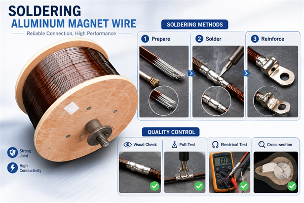
The complete process flow for enameled aluminum wire welding – from conductor preparation to final inspection – includes the following sequence: Incoming wire inspection (conductor diameter, enamel coating grade, coil integrity) → Enameled coating removal at joint location → Visual inspection of the conductor after removal → Pre-welding cleaning (if required) → Welding using the selected method (ultrasonic/resistance/laser/brazing) → Post-welding cooling → Joint cleaning → Anti-corrosion coating → Joint sealing → Quality inspection (Section 4).
IV. Quality Inspection and Acceptance Standards
4.1 Visual Inspection (100%)
Each welded joint shall be visually inspected at a magnification of not less than 10x according to IPC-A-610 acceptance standards. The joint shall have a uniform, bright appearance, free from visible cracks, porosity, undercut, or exposed aluminum substrate. There shall be no signs of heat damage, scorching, or blistering in the adjacent enamel coating, and the damage area shall not extend more than 2 mm beyond the joint edge.
4.2 Mechanical Strength Testing (Sampling)
Tensile testing shall be conducted on samples (5-10 joints per batch) of production batches using a calibrated tensile testing machine at a crosshead speed of 25 mm/min, according to ASTM D3039 standards. The acceptance criterion is that the tensile strength of the joint shall not be less than 60% of the strength of the aluminum conductor, and the fracture shall occur at the aluminum conductor rather than the joint interface—indicating that the joint is not a weak point in the mechanical assembly.
4.3 Resistance Measurement (100%)
Measure the joint resistance using a four-wire milliohm meter or Kelvin bridge (minimum resolution 0.01 mΩ). Acceptance criteria are a 18 AWG joint resistance not exceeding 1.0 mΩ and batch-to-batch resistance variation not exceeding ±15%. Measurements should be performed after the joint has cooled to ambient temperature (23 ± 5°C) to eliminate the effects of thermoelectricity.
4.4 Insulation Withstand Voltage Test (100%)
Measure the insulation resistance between the welded joint and the adjacent unwelded conductor section at 500 V DC using a megohmmeter, according to UL 1446 Section 23. Acceptance criteria are a resistance of not less than 100 MΩ. For applications with rated voltages exceeding 48 V AC or 60 V DC, an additional withstand voltage test of 2 times the operating voltage + 1,000 V for 60 seconds should be performed.
4.5 Metallographic Inspection (Critical Batch)
For the first batch of process validation, parameter changes, and batches with a frequency of no less than one per quarter, metallographic sections of representative joints should be performed according to ASTM E3 and ASTM E1351 standards. Acceptance criteria include: no porosity, inclusions, or lack of fusion at the joint interface; metallurgical bonding layer thickness of no less than 5 μm; and no signs of overheating in the heat-affected zone (coarse grains, eutectic melting).
V. Conclusion
Reliable connections of enameled aluminum wire require a systematic process approach. The three core challenges of aluminum metallurgy—oxide film damage, heat input control, and post-weld corrosion protection—can be addressed through the standardized application of one of four mature welding methods. For most transformer winding applications of 18-24 AWG aluminum conductors, ultrasonic welding according to AWS C1.1 provides the optimal combination of joint strength, production cycle time, and process repeatability, while resistance spot welding is the preferred method for high-volume, lower-strength applications.
Engineers specifying the aluminum conductor connectors should select the connection method based on wire diameter, production volume, and required operating conditions, and verify the process through the five quality inspection procedures described herein. When evaluating suppliers, purchasers should not only focus on the quality of the enameled wire but also examine their technical capabilities in providing connection process support—including parameter optimization, tooling design, and initial metallographic verification.