


1 Introduction
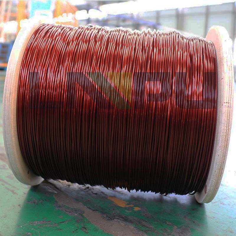
Enameled copper wire is one of the most widely used winding wires in the electrical and electronic industries, and its insulation performance directly determines the operational reliability and service life of electrical equipment such as motors, transformers, and inductors. However, in practical engineering, insulation breakdown failure of enameled copper wire is one of the main causes of winding failures. A deep understanding of the failure mechanism of insulation breakdown is of great significance for winding wire engineers, equipment manufacturing engineers, and reliability engineers.
Based on the NEMA MW 1000-2018, IEC 60317 series, and IEC 60851 test method standards, this paper systematically analyzes the main causes and mechanisms of insulation breakdown failure of enameled copper wire, and discusses them from seven dimensions: thermal aging, electrical stress, mechanical damage, chemical corrosion, moisture intrusion, manufacturing defects, and overload impact.
2 Overview of Failure Mechanisms
The insulation breakdown of enameled copper wire is essentially a physicochemical process in which the enamel coating transforms from an insulating state to a conductive state. Based on failure mode, it can be divided into two main categories: intrinsic breakdown and engineering breakdown. Intrinsic breakdown is determined by the dielectric strength limit of the enamel coating material and is an inherent physical failure mode of enameled wire. Engineering breakdown is caused by the long-term coupling of multiple stresses, including thermal, electrical, mechanical, and chemical stresses, and is the main failure mode of enameled wire in engineering applications.
Based on the failure timescale, breakdown can be divided into instantaneous breakdown and progressive breakdown. Instantaneous breakdown occurs within seconds to minutes and is often caused by sudden factors such as overvoltage, short circuit, and mechanical shock. Progressive breakdown occurs within months to years and is often caused by long-term cumulative effects such as thermal aging, corona corrosion, and chemical erosion.
Based on the failure location, breakdown can be classified into conductor interface breakdown, internal breakdown, surface breakdown, and air interface breakdown. Different breakdown locations correspond to different failure mechanisms and preventive measures.
3 Main Reason 1: Thermal Aging Failure
3.1 Thermal Aging Mechanism
The primary cause of insulation breakdown in enameled copper wire is long-term thermal aging. When the operating temperature of the enameled wire exceeds the thermal settling temperature of the enameled coating, the molecular chains inside the enameled coating break, oxidize, and degrade, causing the dielectric strength to gradually decrease until breakdown occurs.
According to Montsinger’s rule of thumb, for every 10 K increase in operating temperature, the insulation life of enameled wire is reduced by approximately half. The thermal rating temperature of enamel coating is a reference temperature; the actual service life depends on many factors, including operating temperature, cumulative time, and thermal aging environment.
3.2 Chemical Processes of Thermal Aging
The thermal aging of enamel coating mainly manifests as the following chemical processes: oxidative degradation of molecular chains, main chain breakage producing low-molecular-weight volatiles and active groups; hydrolytic breakage of functional groups such as ester bonds, amide bonds, and imide bonds; internal stress relaxation of enamel coating leading to the generation of microcracks; and copper ions catalyzing the oxidation reaction of enamel coating at high temperatures.
Polyurethane enamel coatings show significant aging at 130 to 155 degrees Celsius; polyester enamel coatings show significant aging at 155 to 180 degrees Celsius; polyester imide and polyamide imide enamel coatings have better heat resistance and can work for extended periods at 180 to 220 degrees Celsius.
3.3 Engineering Identification of Thermal Aging
The outward appearance of thermally aged enamel coatings is characterized by a color change from light yellow to dark brown to black; the surface loses its luster, becomes brittle, and is easily peeled off. Microscopic characteristics include a thinning of the enamel coating thickness, a decrease in internal molecular weight, and a 30% to 50% decrease in dielectric strength. The actual service life of enameled wires can be predicted through accelerated thermal aging tests, i.e., extrapolation using the Arrhenius model.
3.4 Preventive Measures for Thermal Aging
During the design phase, select an enameled wire with a thermal level temperature 10 to 20 K higher than the actual operating temperature; during the operation phase, control the winding temperature rise to ensure that the hot spot temperature does not exceed the enameled coating thermal level; during the maintenance phase, regularly test key indicators such as winding insulation resistance and dielectric loss tangent.
4. Main Reason Two: Electrical Stress Failure
4.1 Breakdown Voltage Aging
Long-term aging of the enameled wire under operating voltage is a significant cause of breakdown failure. Even if the operating voltage is lower than the instantaneous breakdown voltage of the enamel coating, long-term electrical stress can still cause progressive damage such as micropores and electrical dendrites inside the enamel coating, ultimately leading to breakdown.
The long-term breakdown voltage of enamel coating is approximately 50% to 70% of the instantaneous breakdown voltage. NEMA MW 1000-2018 specifies the minimum breakdown voltage of enameled round wire, which depends on the enamel coating grade and wire diameter: AWG 24 to 30, approximately 1500 to 7500 volts; AWG 14 to 22, approximately 1500 to 7500 volts; and AWG 4 to 13, approximately 750 to 1500 volts.
4.2 Partial Discharge and Corona
Partial discharge is a core cause of insulation failure in high-voltage motors and transformer windings. Tiny air gaps on the conductor surface, inside the coating, and at the coating-air interface generate localized ionization discharges under the influence of an electric field. The released high-energy electrons and active groups gradually erode the coating, forming electrical dendrite damage channels, ultimately leading to breakdown.
Partial discharge occurs when the electric field strength exceeds the breakdown field strength of the gas. The breakdown field strength of tiny air gaps inside the enamel coating is approximately 3 kilovolts per millimeter, while that of tiny air gaps in air is approximately 1 kilovolt per millimeter. Surface roughness, burrs, and uneven thickness of the enamel coating can all cause localized electric field concentration, leading to partial discharge.
4.3 Pulse Voltage Impact
The motor windings driven by PWM inverters are subjected to high-frequency pulse voltage impacts, with du/dt reaching 5 to 10 kV per microsecond. These high-frequency pulses generate cumulative effects within the enamel coating, such as dielectric loss, space charge accumulation, and electromagnetic vibration, accelerating the aging of the enamel coating.
According to IEC 60034-18-41, the inter-turn insulation of variable frequency motor windings should withstand a pulse voltage test of more than twice the rated voltage. Ordinary wire has a significantly shortened lifespan in PWM applications; therefore, it is necessary to select corona-resistant or fiberglass-coated wire specifically designed for variable frequency motors.
4.4 Preventive Measures for Electrical Stress Failure
The use of corona-resistant enameled wire, with the addition of inorganic nanofillers to its enamel coating, significantly enhances its resistance to partial discharge (PD). Optimized winding manufacturing processes prevent mechanical damage to the enamel coating and conductor burrs. A dedicated insulation system is used for variable frequency motor applications. Regular partial discharge testing is conducted to promptly identify potential breakdown risks.
5. Main Reason 3: Mechanical Damage Failure
5.1 Damage during Thread Embedding and Shaping
During the manufacturing processes of motor stator winding, winding shaping, and end binding, the enameled wire is subjected to various mechanical stresses such as bending, tension, compression, and friction. When the stress exceeds the elastic limit of the enameled coating, the enameled coating will crack, peel, and fall off, and the dielectric strength will decrease significantly.
According to IEC 60851-3, enameled wire should pass the specified flexibility and adhesion tests. The enamel coating of round wire should not crack after bending along a mandrel diameter of 1d to 5d. The crack resistance of the enamel coating in rectangular wire is worse than that of round wire when bent along its long side, requiring special processing to ensure its integrity.
5.2 Vibration and Shock During Operation
The stator and rotor windings of an electric motor are subjected to multi-source vibrations during operation, including electromagnetic vibration, mechanical vibration, and thermal cyclic stress. Long-term vibration leads to enamel coating fatigue and the formation of microcracks. Sudden short circuits, overloads, and mechanical impacts can cause the enamel coating to crack within seconds to minutes.
The frequency and amplitude of vibration are key parameters affecting the lifespan of enamel coatings. Electromagnetic vibration frequencies are twice the power supply frequency, i.e., 100 Hz or 120 Hz, while mechanical vibration frequencies range from 5 to 2000 Hz. The cumulative effect of vibration can be assessed through accelerated vibration testing.
5.3 Thermomechanical Stress
When the winding experiences temperature changes, thermomechanical stress arises due to the difference in the coefficients of linear expansion between the copper conductor and the enamel coating. The coefficient of linear expansion for copper is approximately 17 × 10⁻⁶ per K, while that for the enamel coating is approximately 60 to 100 × 10⁻⁶ per K, a difference of 3 to 6 times. Frequent thermal cycling causes shear stress at the interface between the enamel coating and the conductor, which, over time, leads to the peeling of the enamel coating.
5.4 Preventive Measures for Mechanical Injury
Select a coating system with strong adhesion and good flexibility; optimize the winding process to reduce stretching and compression of the coating; use soft insulating material for end binding to avoid hard friction; regularly check the winding vibration level to detect abnormalities in a timely manner.
6 Main Reason Four: Chemical Corrosion Failure
6.1 Moisture and Water
Moisture is a common cause of insulation failure in enameled wires. Enameled coatings undergo hydrolysis under the influence of water molecules, particularly polyester and polyurethane enameled coatings. When moisture penetrates the enameled coating, the dielectric strength decreases significantly, and the dielectric loss tangent increases by one to two orders of magnitude.
The breakdown voltage of enameled wire in a humid environment decreases by 30% to 70% compared to a dry environment. According to IEC 60851-4, enameled wire should pass a damp heat test. The damp heat test is typically conducted at 40 degrees Celsius and 95% relative humidity for 56 days or longer.
6.2 Chemical Media Erosion
Chemical media such as acids, alkalis, salt spray, oil mist, and solvents corrode the surface of the enamel coating, gradually penetrating to the conductor interface and causing breakdown. Enameled wires used in offshore wind power, mining, and chemical industries are susceptible to chemical corrosion.
Polyamide-imide (enamel coating) exhibits superior chemical resistance compared to polyester and polyurethane (enamel coating), making it the preferred choice for chemically corrosive environments.
6.3 Copper Ion Migration
Copper ions migrate from the conductor to the enamel coating surface under the influence of an electric field and water molecules, forming conductive channels and leading to breakdown. Copper ion migration is particularly significant under high humidity and high voltage conditions.
Copper ion migration can be mitigated by processes such as nickel plating, tin plating, and silver plating on the conductor surface. Adding ion-scavenging agents to enamel coatings can also inhibit copper ion migration.
6.4 Preventive Measures for Chemical Corrosion
A chemical-resistant enamel coating system is selected; after winding manufacturing, vacuum pressure impregnation is performed to fill the micropores of the enamel coating; insulation resistance is tested regularly to detect moisture intrusion in a timely manner; in chemical corrosion scenarios, fiberglass-encased enameled wire is used instead of single enameled wire.
7. Main Reason Five: Manufacturing Defects Leading to Failure
7.1 Uneven thickness of enamel coating
During the manufacturing process of enameled wire, fluctuations in the enameled coating process can lead to uneven enameled coating thickness. Thinner areas of enameled coating have a dielectric strength 30% to 50% lower than thicker areas, making them prime locations for breakdown failure.
NEMA MW 1000-2018 specifies the minimum and maximum thickness requirements for enamel coatings. The uniformity of enamel coating thickness is one of the key indicators of enameled wire quality.
7.2 Conductor Surface Defects
Defects such as burrs, scratches, oxide scale, and impurities on the conductor surface can lead to localized stress concentration or insufficient coating thickness, resulting in a significant decrease in dielectric strength. The surface roughness of the conductor should be controlled below 1.6 micrometers.
7.3 Incomplete curing of enamel coating
If the curing temperature of the enamel coating is too low or the curing time is insufficient, the enamel coating will not cure completely. Problems such as residual solvent, residual stress, and insufficient molecular weight will lead to a decrease in dielectric strength and mechanical strength.
7.4 Preventive Measures for Manufacturing Defects
Strengthen raw material inspection; conductor surface roughness and chemical composition should meet standard requirements; optimize the enamel coating process; control the enamel coating thickness uniformity deviation within ±10%; strictly control the curing process; curing temperature and time should meet process specifications; finished product inspection includes key tests such as breakdown voltage, enamel coating continuity, and voltage resistance.
8 Main Cause Six: Overload and Short Circuit Failure
8.1 Short-circuit electrodynamic impact
When a motor winding experiences a sudden short circuit, it withstands a short-circuit current tens to hundreds of times its rated current, resulting in an electrodynamic force 25 to 49 times that under rated operating conditions. This short-circuit electrodynamic force leads to winding end deformation, insulation damage, enamel coating rupture, and instantaneous breakdown failure.
8.2 Overload Thermal Shock
When a motor is overloaded, the current exceeds the rated value, increasing copper losses and causing a sharp rise in winding temperature. A short-term overload can cause the enamel coating temperature to exceed the thermal stage temperature within minutes, resulting in thermal breakdown.
According to IEC 60034-1, the motor should be able to operate for a short period of time at 1.2 times the rated current, and the winding temperature rise should not exceed the specified short-time overload temperature rise limit.
8.3 Overload and Short Circuit Prevention Measures
During the design phase, ensure that the dynamic and thermal stability of the windings meet the requirements of IEC 60034-1; select wires with a higher thermal class than conventional wires or fiberglass-coated wires; configure comprehensive overload and short-circuit protection devices; and regularly inspect the winding condition to promptly detect potential faults.
9 Main Cause Seven: Environmental Stress Failure
9.1 Temperature Cycling
When the ambient temperature changes, the windings of the equipment are subjected to thermal cycling. The difference in the coefficients of linear expansion between the enamel coating and the copper conductor causes interfacial stress, and frequent thermal cycling leads to fatigue and peeling of the enamel coating.
Wind power, rail transit, and outdoor equipment are high-frequency and high-amplitude temperature cycling scenarios, making them high-risk environments for environmental stress failure.
9.2 Ultraviolet Radiation and Ozone
Ultraviolet radiation and ozone have a degrading effect on enamel coatings. In outdoor equipment, high-altitude areas with strong ultraviolet radiation, and environments with ozone inside electrical equipment, enamel coatings age more rapidly.
Polyimide (enamel coating) has better UV resistance than polyester and polyurethane (enamel coating).
9.3 Dust and Pollution
The deposition of contaminants such as dust, salt spray, oil mist, and conductive particles can lead to failure modes such as leakage current, creepage, and corrosion on the surface of the wire.
Protective measures include: vacuum pressure impregnation to fill pores after winding manufacturing; equipment enclosure protection rating of IP54 or higher; and regular cleaning of winding surfaces.
10 Failure Comprehensive Analysis and Diagnosis
The breakdown failure of enameled copper wire insulation is often the result of multiple factors working together. For example, the breakdown failure of motor windings may involve the coupled effects of multiple factors such as thermal aging, electrical stress, mechanical vibration, and moisture intrusion.
Failure diagnosis should follow the following procedure: Macroscopic inspection of the appearance, color, and integrity of the enamel coating; Electrical testing to measure insulation resistance, dielectric loss tangent, and breakdown voltage; Chemical analysis of the enamel coating composition and degree of thermal aging; Mechanical inspection of the enamel coating adhesion and flexibility; Operational history analysis of temperature records, load history, and fault history.
Comprehensive diagnosis can pinpoint the main causes of breakdown failure, providing a basis for subsequent engineering improvements.
11 Engineering Improvement Suggestions
To address the various causes of insulation breakdown failure in enameled copper wires, engineering improvements can be made in the following aspects:
Regarding material selection: use wires with a thermal class higher than that required for actual operating conditions, or wires with fiberglass wrapping; use polyamide-imide coating for chemical corrosion scenarios; use corona-resistant wires for variable frequency motor applications; and use moisture-proof wires for high humidity scenarios.
In terms of structural design: optimize the winding structure design to reduce electric field concentration; increase the thickness of inter-turn insulation to improve dielectric margin; and adopt a composite insulation system to improve overall reliability.
In terms of process optimization: strictly control the enamel coating process to improve the uniformity of the enamel coating; use vacuum pressure impregnation to fill the pores of the enamel coating; and optimize the wire embedding process to reduce mechanical damage.
In terms of operation and maintenance: regularly check winding temperature, insulation resistance, and dielectric loss; monitor partial discharge and promptly detect potential breakdown risks; establish equipment operation records and analyze fault patterns.
12 Conclusion
Insulation breakdown in enameled copper wire is one of the main failure modes in electrical equipment such as motors, transformers, and inductors. Its causes involve multiple dimensions, including thermal aging, electrical stress, mechanical damage, chemical corrosion, moisture intrusion, manufacturing defects, overload impact, and environmental stress. A deep understanding of various failure mechanisms is of great guiding significance for wire selection, winding design, manufacturing processes, and operation and maintenance.
In engineering practice, appropriate types of wire and insulation systems should be selected based on the specific operating conditions of the application scenario. Through strict process control and operation and maintenance, the probability of insulation breakdown failure should be minimized, thereby improving the reliability and service life of electrical equipment.
Contact Information:
- E-mail: office@cnlpzz.com
- WhatsApp: 0086-19337889070
- Zhengzhou LP Industry Co., Ltd.