


I. Introduction: Electrification and Insulation Challenges of Distribution Cabinets
1.1 Four Main Forms of Industrial Distribution Cabinets
Industrial distribution cabinets come in various forms, but can be categorized into four main types based on voltage level and application function. Low-voltage distribution cabinets (LV Panel, rated voltage ≤ 1 kV) are the most common equipment in factory workshops, responsible for distributing 400V three-phase power to various power branches; medium-voltage switchgear (MV Switchgear, 3~35 kV) are used in substations and factory main distribution rooms; motor control centers (MCCs) are the “main force” of industrial control cabinets, used for centralized control of the start, stop, and protection of multiple motors; PLC/relay control cabinets (Control Panels) handle automated logic control, with the highest wiring density and a mix of signal and power lines. Among these four types, fiberglass-coated wiring is mainly used in the first three categories (power distribution, switching, and control), especially in scenarios requiring high temperature resistance, high mechanical strength, or high current output.
1.2 The Five Stringent Requirements for Insulated Wires in Distribution Cabinets
Unlike household wiring or ordinary mechanical wiring harnesses, the requirements for insulated wires in distribution cabinets can be summarized in five points. First, high temperature resistance—the busbars, reactors, and local hot spots within the cabinet can reach 130–180°C. PVC’s long-term temperature resistance is only 70°C, XLPE 90°C, while only fiberglass-insulated wire can reach H-level (180°C) or even C-level (200°C). Second, short-circuit electromagnetic force resistance—the instantaneous electromagnetic force generated by a large short-circuit current can reach tens of thousands of Newtons. Fiberglass-insulated wire plays a buffering and voltage equalization role in the busbar insulation. Third, chemical resistance—the cabinet may come into contact with transformer oil, mineral oil, cleaning agents, and humid environments. The fiberglass outer impregnation varnish (silicone organic varnish, modified organic silicone) can effectively resist these. Fourth, flame retardant and low smoke—In the event of a short circuit, the flame-retardant fiberglass insulation prevents the spread of flame, meeting standards such as GB/T 11022 and IEC 61439. Fifth, long-term reliability—The distribution cabinet is designed for a lifespan of 20–30 years; the insulation layer must not fail prematurely due to thermal aging or mechanical fatigue.
II. Structure and Material System of Fiberglass Insulation
2.1 Typical Structural Layers: Conductor → Enamelled Coating → Fiberglass → Impregnated Varnish
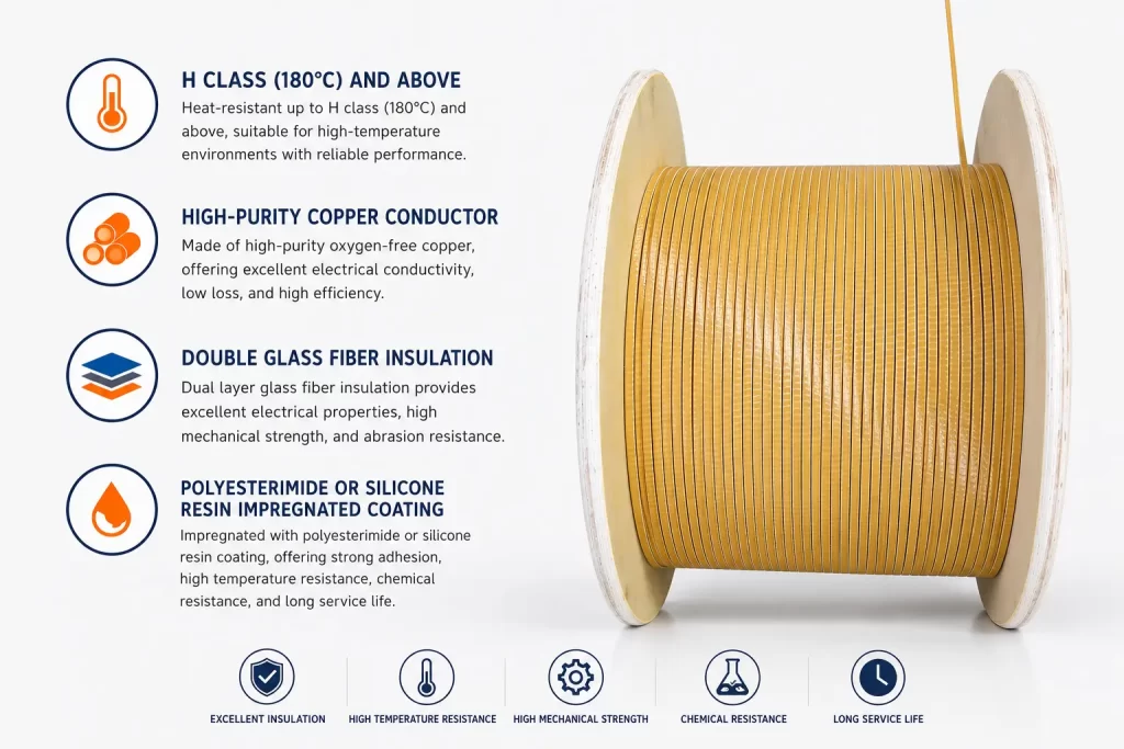
Fiberglass-insulated wire for distribution cabinets is not a single material, but a four-layer structure composite insulator. The innermost layer is copper or aluminum conductor (round wire AWG 14–30, or rectangular flat wire 1.0–5.0 mm thick, 3.0–15.0 mm wide), which carries current transmission; the second layer is high-temperature resistance enamel coating (PEI polyester/PAI polyamide-imide/PI polyimide), providing basic insulation and thermal class; the third layer is alkali-free glass fiber (E-glass) tightly wound in a spiral on the surface of the enameled wire, providing mechanical strength and heat resistance; the fourth layer is impregnated varnish (silicone varnish, modified silicone, polyester), which, after baking and curing, forms a smooth and tough outer surface, providing chemical resistance, flame retardancy, and moisture resistance. Each layer is irreplaceable:** The enamel coating determines temperature resistance, the fiberglass determines mechanical properties, and the impregnation varnish determines environmental adaptability.
2.2 Fiberglass Types: E-glass vs. S-glass
Fiberglass used in distribution cabinets is primarily E-glass (alkali-free glass), with an alkali metal oxide content of <1%, excellent electrical insulation performance, mechanical strength meeting wrapping requirements, and a moderate price. S-glass (high-strength glass) has a higher silica content and approximately 30% higher tensile strength than E-glass, but it is 2-3 times more expensive and is mainly used in military, aerospace, or extreme mechanical strength applications. E-glass is used almost exclusively in distribution cabinets. There are two types of fiberglass winding methods: Single-layer winding (PG1) is suitable for general applications, while double-layer winding (PG2) is suitable for applications requiring higher breakdown voltage or needing to pass the IEC 61439 reinforced insulation test.
2.3 Inner Enamel Coating System
: The PEI / PAI / PI enamel coating determines the “upper temperature limit” of the fiberglass insulation. H-class (180°C) Fiberglass insulation typically uses a PEI (polyester imide) inner enamel coating, corresponding to NEMA MW 30-C (round wire) or MW 71-C (rectangular); C-class (200°C) uses a PEI + PAI (polyamide-imide) double coating, corresponding to NEMA MW 35 / MW 36; C+-class (220–240°C) requires a PI (polyimide) enamel coating, corresponding to NEMA MW 16 / MW 20. Distribution cabinets most commonly use H-class PEI single coating or PEI+PAI double coating, sufficient to cover 90% of application scenarios.
2.4 External Impregnation Varnishes
: There are three main systems for impregnating the outer surface of fiberglass: silicone varnish, modified silicone varnish, and polyester varnish. Silicone varnish has a temperature resistance up to 200°C, good flexibility, and is commonly used for H-class fiberglass wiring. Modified silicone varnish strikes a balance between temperature resistance and adhesion, with a price between silicone varnish and polyester varnish, making it the “mainstay” for busbar wrapping in distribution cabinets. Polyester varnish has the lowest cost and is suitable for F-class (155°C) applications. NEMA MW 1000 stipulates that impregnating varnishes must be electrical grade and maintain performance in the accelerated thermal aging test of MW 1000 Part 3 §3.58.
2.5 Round Wire vs Flat Wire: Selection of Busbars and High-Current Lead-Outs
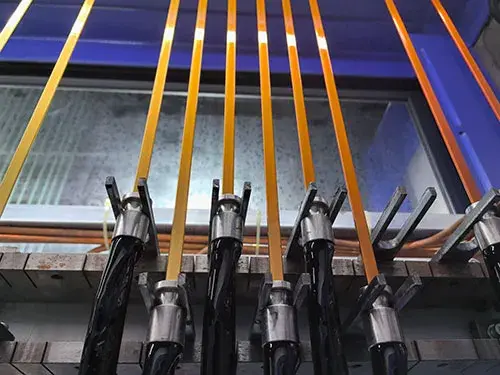
Traditional fiberglass-insulated wire primarily uses round wire (AWG 18–30) for secondary wiring within cabinets, relay/contactor coils, and transformer secondary windings. Since 2010, rectangular flat wire has been widely adopted for high-current leads (above 200 A) and dry-type transformer low-voltage windings in distribution cabinets—flat wire offers a smaller surface area, higher space utilization, and better heat dissipation for the same cross-sectional area. LNPU 180-grade fiberglass-insulated enameled flat copper wire is specifically designed for this application: fiberglass is tightly wound around the surface of the flat copper wire and then impregnated with enamel, achieving a breakdown voltage of 1,350 V (single-layer enamel, Class 1) to 2,560 V (double-layer enamel, Class 2), and can withstand the hard bending of busbars and the shaping of leads.
III. Key Performance Characteristics of Fiberglass-Insulated Wire for Distribution Cabinets
3.1 Thermal Class
: The thermal class of H-class/C-class/C+-class distribution cabinets is directly determined by the internal enamel coating. H-class (180°C) is suitable for most low-voltage distribution cabinet busbars, control cabinet secondary wiring, and small transformer windings; C-class (200°C) is suitable for transformer windings in switchgear, high-current leads in MCCs, and windings near heat sinks; C+-class (240°C) is suitable for current transformers in medium-voltage switchgear, internal windings of oil-immersed transformers, and leads near heat-generating components. The most common selection error is selecting wiring based on “maximum operating temperature + 5°C margin,” but this margin is far from sufficient in distribution cabinets—the actual temperature near busbar contacts, reactors, and thyristor heat sinks may be 20–40°C higher than the nominal value. **
3.2 Breakdown Voltage and Dielectric Strength
** The breakdown voltage of fiberglass-coated wire is contributed by both the inner enamel coating and the fiberglass. According to NEMA MW 1000-2018, the minimum breakdown voltage of 10–23.5 AWG fiberglass-coated round copper wire is: 360 V for a single layer (based on the enamel coating), and 540 V for a double layer. For rectangular flat wire (polyester fiberglass coating), the minimum breakdown voltage of Class 1 enamel coating + double-layer fiberglass can reach 1,560 V (GB/T 7673 standard), and Class 2 enamel coating + double-layer fiberglass can reach 2,560 V. For the primary winding of current transformers in medium-voltage switchgear (10 kV), a withstand voltage test of 30 kV or higher is required, and a composite insulation structure of multiple layers of enamel coating + multiple layers of fiberglass is usually adopted.
3.3 Chemical Resistance
The chemical media that may be encountered inside the distribution cabinet are far more complex than imagined: transformer oil (mineral oil, synthetic esters), SF6 decomposition products from the switchgear, cleaning agents, humid air, and salt spray (coastal or industrial environments). The chemical resistance of fiberglass-coated wires mainly comes from the external impregnation varnish—silicone varnishes perform well against mineral oils and synthetic esters, but have limited resistance to strong acids and alkalis; modified silicone varnishes have better oil resistance; polyester varnishes have poor chemical resistance and are mostly used in Class F non-oil environments. Therefore, oil-impregnated transformer internal leads and switchgear CT/PT windings are usually impregnated with silicone varnishes or modified silicone varnishes.
3.4 Mechanical Properties: Vibration Resistance, Shock Resistance, and Abrasion Resistance
Distribution cabinets are subjected to continuous vibration (5–500 Hz) and occasional impacts (such as during transportation, installation, and short-circuit electrodynamics) during operation, especially the switchgear busbars, MCC motor control cabinet leads, and reactor windings. The core function of the fiberglass layer is to enhance mechanical strength. NEMA MW 1000 stipulates that the fiberglass sheath must be wound on a mandrel with a wire diameter of 10 times the diameter without exposing the bare conductor; simultaneously, the elastic rebound angle must be controlled within 5° (4/0–13 AWG fiberglass-covered bare copper) and within 5.5° (4–13 AWG fiberglass-covered enameled copper) to ensure stable forming on automated production lines.
3.5 Flame Retardancy and Low Smoke: Meeting the flame retardancy requirements of GB/T 11022 / IEC 61439 for distribution cabinets
is directly related to personnel and equipment safety. GB/T 11022 “Common Technical Requirements for High Voltage Switchgear and Controlgear Standards” and IEC 61439 “Low Voltage Switchgear and Controlgear Assemblies” both specify the flame retardancy rating (usually V-0) and smoke density index of insulation materials. The flame retardant formulation of the impregnating varnish for fiberglass sheathing is the key to determining whether it can pass the cabinet-level flame retardancy test. LNPU fiberglass sheathing uses modified silicone impregnation varnish, with an oxygen index ≥ 32% and a self-extinguishing time ≤ 10 seconds, far exceeding PVC’s 25 seconds or more, meeting the flame retardant requirements of IEC 61439-1 §10.10.
IV. Typical Application 1: transformer Winding
4.1 Dry-Type Transformer Low-Voltage Windings
Dry-type transformers rely on air or epoxy resin insulation and do not require oil immersion. Therefore, the windings must use high-temperature resistance (HT) wire of Class F (155°C) or higher. Class H fiberglass-coated enameled flat copper wire is the mainstream choice for low-voltage windings in dry-type transformers—the composite structure of fiberglass + enamel coating can operate for more than 20 years at 180°C and is solvent-free and environmentally friendly. LNPU Class 180 fiberglass-coated enameled flat copper wire is available in specifications of 1.0–5.0 mm × 3.0–15.0 mm, covering the needs of dry-type transformers from 50 kVA to 2,500 kVA.
4.2 Oil-Immersed Transformer Internal Leads
The internal leads of an oil-immersed transformer (including low-voltage side leads, high-voltage tap leads, and winding connections) must withstand an oil temperature of 105°C plus short-circuit impact. Class C fiberglass-coated enameled round copper wire is the standard choice for internal leads of oil-immersed transformers—the outer silicone varnish provides oil resistance, and the inner PAI layer provides 200°C temperature resistance. NEMA MW 35-C (PEI+PAI double-coated fiberglass-coated round copper wire) is the internationally accepted specification for oil-immersed transformer leads.
4.3 Interlayer Insulation and End Reinforcement
Interlayer insulation and end reinforcement of transformers typically use fiberglass tape or fiberglass cloth. However, at the end leads of high-voltage windings, partial use of fiberglass-coated wire is required instead of enameled wire—because the electric field is concentrated at the end, the temperature is high, and creepage is prone to occur. The requirements for fiberglass-coated wire in this application are: breakdown voltage ≥ 5 kV, flame retardant, and oil resistant. A “luxury” configuration of 2-grade enamel coating + double-layer fiberglass + silicone organic varnish impregnation is typically used.
4.4 Reactors and Inductors
Reactors, inductors, and filter inductors in distribution cabinets are typically wound with H-grade fiberglass-coated enameled round copper wire. In addition to insulation, the fiberglass layer also suppresses the skin effect and improves mechanical stability. In high-power harmonic filters, LNPU MW 35-C (PEI+PAI double-coated Class C) is commonly used to withstand a steady-state temperature rise of 200°C and high-frequency eddy currents at switching frequencies of 5–20 kHz. —
V. Typical Application Two: Instrument Transformer Windings
5.1 Current Transformer (CT) Primary and Secondary Windings
A current transformer (CT) is the “current sensor” of a distribution cabinet. Its primary winding typically has only one to a few turns, connected in series in the main circuit; the secondary winding has hundreds to thousands of turns, outputting a 5 A or 1 A standard signal. The primary winding uses Class C fiberglass-insulated enameled round copper wire, and the secondary winding uses Class H fiberglass-insulated enameled round copper wire. CT windings have extremely high insulation requirements, especially the primary winding of a 10 kV medium-voltage CT, which must pass a 30 kV/1 min power frequency withstand voltage test and a 75 kV lightning impulse test.
5.2 Voltage Transformer (PT) Primary and Secondary Windings
The insulation requirements for a voltage transformer (PT) are similar to those for a current transformer (CT), but the PT has more turns and a finer wire diameter (AWG 28–34), commonly using H-class fiberglass-coated enameled round copper wire. LNPU MW 30-C (PEI single-coated fiberglass-coated round copper wire) is an internationally recognized specification for PT secondary windings, offering stable electrical performance, good mechanical strength, and long service life.
5.3 Zero-Sequence Current Transformer and Residual Current Transformer
Zero-sequence current transformers (Zero-Sequence CTs) and residual current transformers (RCD/RCCB internal CTs) use a toroidal core, passing through three phases and four wires, to detect zero-sequence current. These CTs are typically wound with hundreds of turns of fine-diameter (AWG 32–40) fiberglass-coated enameled round copper wire, requiring extremely high inter-turn insulation and moisture resistance. Fiberglass-insulated wire is irreplaceable in this scenario—enameled wire is prone to breakdown in humid environments, while composite insulation of fiberglass and impregnated varnish can operate for extended periods at 95% relative humidity.
VI. Typical Application Three: Switchgear and Control Cabinets
6.1 High-current busbar sheathing
The main busbar inside the switchgear is typically made of bare copper or tin-plated copper. To prevent phase-to-phase short circuits, electric shock, and electrochemical corrosion, it is often covered with fiberglass tape or fiberglass sheathing. LNPU fiberglass-coated enameled flat copper wire is used directly on the busbar itself—that is, an “insulated busbar.” This is more reliable and space-saving than the “bare busbar + fiberglass tape sheathing” process, with a breakdown voltage of up to 2,560 V (double-layer enamel, Class 2) and flame retardant V-0 rating. This application is becoming increasingly common in 800 V DC distribution cabinets, data center HVDC busbars, and high-voltage distribution boxes for new energy vehicles. **
6.2 Secondary Circuit Wiring
** The secondary circuit of the switchgear includes the measurement circuit (CT/PT secondary side), control circuit (circuit breaker opening and closing coils, relays, indicator lights), and protection circuit (overcurrent, instantaneous, and differential protection). Secondary circuit wiring typically uses AWG 18–22 fiberglass-insulated enameled round copper wire, with a temperature rating of H and flame retardant rating of V-0. This facilitates wiring in dense terminal blocks, provides clear labeling, and is less prone to damage. GB/T 11022 §6.2 explicitly requires that secondary circuit conductors have a temperature resistance ≥ 90°C. In practical engineering, selecting H-grade fiberglass-insulated wire can significantly improve reliability.**
6.3 Control Cabinet Relays and Contactor Coils
** The coils of intermediate relays, contactor coils, push-button switches, thermal relays, solid-state relays, and other low-voltage electrical appliances in the control cabinet are typically wound with enameled round copper wire. In high-temperature applications (near heat sinks, busbar contacts, thyristors) or applications requiring resistance to mechanical shock, using fiberglass-insulated enameled copper wire instead of ordinary enameled wire can significantly extend coil life. For example, high-current AC contactors (above 100 A) in MCC motor control cabinets operate at 130–150°C for extended periods. Ordinary enameled wire may break down due to thermal aging within 5 years, while fiberglass-insulated wire can extend this life to 15–20 years.
6.4 PLC and Instrument Signal Lines
Although PLC signal lines, analog signal lines, and communication lines generally use shielded twisted-pair cables, in applications near high-current busbars or strong electromagnetic interference sources, adding a fiberglass braided layer to the signal lines or using fiberglass-insulated multi-core cables can effectively shield against electromagnetic interference (EMI) and provide mechanical protection. LNPU Fiberglass-inlaid Multi-Core Control Cable is available in 2–24 core configurations, with conductor AWG 18–24 and fiberglass braid coverage ≥ 80%. It is widely used in control cabinets in power plants, substations, metallurgy, and petrochemical industries. —
VII. Typical Application Four: MCC Motor Control Center
7.1 High Current Leads
MCC motor control centers are used to centrally control multiple motors. Each motor’s leads (from the contactor to the motor junction box) need to carry tens to hundreds of amperes. Leads above 100 A typically use rectangular fiberglass-insulated enameled flat copper wire, which is more compact, easier to bend, and easier to route in confined spaces than round wire. For example, a 200 A motor lead requires a 70 mm² cross-sectional area; round wire, with a diameter of approximately 10 mm, is difficult to route. Using 5 mm × 14 mm flat wire, only 14 mm wide, allows for easy routing into a standard MCC unit compartment.
7.2 Reversible Start and Star-Delta Start
MCC units with forward-reverse start and star-delta start require frequent contactor switching, each switch generating a 5–10 times higher starting current surge. Fiberglass-insulated enameled flat copper wire on the contactor output side is 30–50% stronger than round wire in terms of electrodynamic strength because flat wire has a more uniform cross-sectional area distribution, better rigidity, and is less prone to deformation under electromagnetic forces. This is crucial for elevators, cranes, and compressor MCCs that experience frequent starts (more than 30 times per hour).
7.3 Inverter Output Cables
Modern MCCs increasingly integrate inverters (VFDs/Variable Frequency Drives). The cables from the inverter output to the motor withstand high-frequency PWM voltages (typical carrier frequencies 2–16 kHz). Ordinary PVC insulated wires can experience voltage reflection, insulation breakdown, and electromagnetic radiation under high-frequency PWM. Fiberglass-insulated enameled flat copper wire with a shielding layer is ideal for inverter outputs: the fiberglass provides high temperature resistance, flame retardancy, and mechanical protection, while the shielding layer suppresses high-frequency EMI. LNPU offers dedicated fiberglass-insulated shielded cables for inverter outputs, covering sizes from 3 × 2.5 mm² to 3 × 120 mm².
7.4 Soft Starters and Capacitor Banks
The output lines of the soft starter and the connection lines of the capacitor bank both need to withstand surge current and harmonic current. H-grade fiberglass-coated enameled round copper wire provides triple protection in these scenarios: temperature resistance, impact resistance, and flame retardancy. Especially for connection lines near the thyristor heatsink, H-grade or C-grade fiberglass-coated wire must be used, as ordinary PVC will age rapidly above 100°C. —
VIII. Selection Decisions and Standards
8.1 Selection Decision Table
The selection of fiberglass-coated wire for distribution cabinets can be based on four dimensions: “temperature + voltage + mechanical + chemical”. The table below provides recommended selections for common application scenarios: | Application Scenario
| Application Scenario | Operating Temperature | Voltage Rating | Recommended Enamel Coating / Thermal Class | Recommended External Impregnation Varnish | Corresponding NEMA Number |
|---|---|---|---|---|---|
| Low-Voltage Switchgear Secondary Wiring | 90–130°C | ≤ 600 V | PEI / H Class (180°C) | Modified Silicone | MW 44-C |
| Low-Voltage Busbar Sheathing | 100–150°C | ≤ 1,000 V | PEI+PAI / C Class (200°C) | Modified Silicone | MW 35 / MW 36 |
| Dry-Type Transformer Low-Voltage Winding | 130–180°C | ≤ 1,000 V | PEI+PAI / C Class | Silicone Varnish | MW 35 / MW 36 |
| Oil-Immersed Transformer Internal Lead | 105°C Oil | ≤ 35 kV | PEI+PAI / C Class | Silicone Varnish | MW 35 |
| Medium-Voltage CT Primary Winding | 90–130°C | 10–35 kV | PI / C+ Class (220°C) | Silicone Varnish | MW 16 |
| PT Secondary Winding | 80–120°C | ≤ 600 V | PEI / H Class | Modified Silicone | MW 30-C |
| MCC High-Current Lead | 130–180°C | ≤ 1,000 V | PEI+PAI / C Class | Modified Silicone | MW 35 |
| VFD Output | 90–150°C | ≤ 1,000 V | PEI / H Class + Shielding | Modified Silicone | MW 44-C + Shielding |
| Contactor/Relay Coil | 120–150°C | ≤ 600 V | PEI / H Class | Modified Silicone | MW 30-C |
| Zero-Sequence CT Winding | 80–120°C | ≤ 600 V | PEI / H Class (Fine Wire) | Silicone Varnish | MW 30-C (AWG 32–40) |
8.2 Key Standards: GB/T 11022 / IEC 61439 / NEMA MW 1000
The core standards that fiberglass-insulated wires used in distribution cabinets must meet include: – GB/T 11022-2020 “Common Technical Requirements for High Voltage Switchgear and Controlgear Standards”: Insulation level, temperature rise, mechanical strength, protection class – GB 50060-2008《Design Specification for 3~110 kV High Voltage Distribution Equipment》: Conductor selection, insulation coordination, and safety distance within the cabinet – IEC 61439-1:2020《Low-voltage switchgear and controlgear assemblies – Part 1: General requirements》: Temperature rise test, dielectric test, and short-circuit withstand strength – NEMA MW 1000-2018《Magnet Wire》: General standard for magnet wire, including breakdown voltage, elastic rebound, and thermal aging of fiberglass-coated wire – GB/T 7673.3-2008《Paper, film, and enameled varnished rectangular copper or aluminum conductor》: Standard for rectangular enameled copper/aluminum wire – IEC 60204-1:2016《Safety of machinery – Electrical equipment for machinery – Part 1: General requirements》: Wiring standard within machinery cabinets
8.3 Comparison with other insulated wires
| Characteristic | PVC Insulated Wire | XLPE Insulated Wire | Fiberglass Covered Enameled Wire | Silicone Rubber Insulated Wire |
|---|---|---|---|---|
| Long-Term Temperature Resistance | 70°C | 90°C | 180–240°C | 180–200°C |
| Flame Retardant V-0 | Difficult | Acceptable | Easy (Modified Paint) | Easy |
| Mechanical Strength | Poor | Medium | Excellent | Medium |
| Chemical Resistance | Poor | Medium | Excellent (Silicone Varnish) | Excellent |
| Breakdown Voltage | Medium | Medium | High | Medium |
| Bending Radius | Small | Medium | Medium | Large |
| Unit Price | Low | Medium | High | High |
| Service Life | 10–15 years | 15–20 years | 20–30 years | 15–20 years |
IX. Typical Failure Modes and Quality Control
9.1 Six Failure Modes of Fiberglass Coated Cables
The main failure modes of fiberglass coated cables used in distribution cabinets include: (1) Thermal Aging – Long-term operation at excessive temperatures leads to degradation of the enamel coating and impregnation varnish, resulting in a decrease in breakdown voltage; (2) Mechanical Damage – Scratching, impact, and excessive bending during installation cause damage to the fiberglass layer; (3) Moisture Absorption Failure – In humid environments, the impregnation varnish cracks, allowing moisture to seep into the conductors; (4) Chemical Corrosion – Oil or cleaning agents dissolve the impregnation varnish, leading to a decrease in insulation performance; (5) Short-Circuit Electrodynamics – During high-current short circuits, the mutual repulsion force between conductors causes insulation deformation; (6) Creep – Long-term high-temperature plastic deformation of the conductor results in uneven insulation thickness.
9.2 Four Key Points of Quality Control
To avoid the above failures, the quality control of fiberglass-coated wire for distribution cabinets should focus on four points: First, conductor quality—copper purity ≥ 99.95%, roundness ≤ 0.02 mm, flat wire thickness tolerance ±0.02 mm; Second, enamel coating integrity—passing the pinhole test (pinhole count ≤ 5/30 m) and breakdown voltage test; Third, fiberglass winding density—coverage ≥ 95%, uniform pitch; Fourth, impregnation varnish curing degree—passing the solvent wiping test (no color fading) and solvent resistance test (no swelling).
9.3 Three Core Questions for Communicating with Suppliers
When inquiring about prices from fiberglass-coated wire suppliers, it is recommended to ask three core questions: (1) Has the enamel coating thermal class passed the NEMA MW 1000 §3.58 accelerated thermal aging test? (2) Is the fiberglass winding a single layer PG1 or a double layer PG2? Does the supplier provide a breakdown voltage type test report? **(3) Is the impregnation varnish silicone organic varnish, modified organic silicone, or polyester? Does the supplier provide a compatibility test report with transformer oil or mineral oil? ** These three questions can filter out 80% of “fake fiberglass wrapped wire” suppliers. —
X. Conclusion
Distribution cabinets are the “heart” of industrial electrical systems. Although the fiberglass insulation inside only accounts for 5-10% of the total cost, it bears more than 50% of the responsibility for reliability. From dry-type transformer windings to MCC high-current leads, from CT/PT transformers to switchgear busbar insulation, and from secondary circuits to inverter outputs, fiberglass insulation, with its comprehensive performance of “high temperature resistance, impact resistance, chemical resistance, flame retardancy, and long lifespan,” has become the “hidden champion” of the distribution cabinet industry. When selecting a distribution cabinet, it is recommended to follow a four-dimensional decision-making process of “temperature + voltage + mechanical + chemical,” quickly matching according to the selection table in Section 8.1 of this document; verifying according to core standards such as GB/T 11022, IEC 61439, and NEMA MW 1000; reverse-checking the supplier’s quality control system according to the six failure modes in Section 9.1 of this document; and selecting qualified suppliers according to the three core issues in Section 9.3 of this document. In the future, with the rise of new scenarios such as 800V DC power distribution, HVDC for new energy vehicles, and high-voltage DC for data centers, fiberglass-insulated wires will evolve towards higher temperature resistance (C+ level 240°C), higher breakdown voltage (≥ 10 kV), and greater intelligence (with fiber optic temperature sensing). Distribution cabinet designers and enameled wire purchasers should plan ahead and proactively establish a new fiberglass-insulated wire supply chain.