


I. Introduction: The Challenges of Automotive Electrification and High-Temperature Wiring Harnesses
1.1 Three Major Electrification Trends in the Automotive Industry
Over the past decade, three clear main trends have emerged in the automotive industry. The first is powertrain electrification, with sales of battery electric vehicles (BEVs) and hybrid electric vehicles (HEVs/PHEVs) rising from less than 1% in 2015 to approximately 22% in 2024, and projected to exceed 50% by 2030. The second is voltage platform upgrades, with traditional gasoline vehicles’ electrical systems remaining at 12V (a few mild hybrids at 48V), while the new generation of pure electric platforms generally uses 400V and is evolving towards 800V or even 900V. The third is intelligentization and wiring harness expansion, with L2+ assisted driving, in-vehicle entertainment, and domain controller architectures continuously increasing the length and complexity of single-vehicle wiring harnesses. These three trends have collectively pushed automotive wiring harnesses to new operational boundaries: higher operating temperatures, higher transient voltages, denser installation space, and more stringent EMC and safety standards. Ordinary PVC insulated wires are no longer sufficient; silicone rubber, Teflon, irradiated cross-linked polyolefin (XLPE), and glass fiber insulated wires have become the mainstays in high-temperature sections.
1.2 Temperature and Voltage Requirements of Traditional and New Energy Wiring Harnesses
The engine compartment of traditional gasoline vehicles operates at 105–125°C for extended periods, with local hotspots (such as turbochargers, exhaust manifolds, and oxygen sensors) reaching 200–250°C. Hybrid vehicles add a drive motor, battery pack, and power electronics outside the engine compartment, extending the operating temperature range to -40°C to +180°C, significantly increasing the heat load on a single system. While the “three-electric” system (battery/motor/electronic control) of pure electric vehicles eliminates the internal combustion engine, the transient heating of the motor controller and fast charging system, as well as the creepage and corona risks of the 800V platform, push insulation requirements to new heights. These changes directly drive the increased penetration rate of glass fiber insulated wires in automotive wiring harnesses.
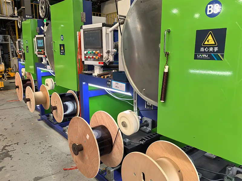
II. Structure and Material System of Fiberglass Insulated Wire
2.1 Typical Structural Layers: Conductor → Enamel Coating → Fiberglass → Impregnating Varnish
Automotive fiberglass insulated wire is not a single material, but a four-layer structure composite insulator. The innermost layer is a copper conductor (round wire or flat wire), the second layer is a high temperature resistance enamel coating (PEI / PAI / PI), the third layer is alkali-free glass fiber (E-glass) tightly wound in a spiral around the enameled wire, and the fourth layer is impregnated with silicone organic varnish or modified silicone varnish, which is baked and cured to form a smooth and tough outer surface. Each layer has its own function: the enamel coating provides basic insulation and thermal class, the fiberglass provides mechanical strength and thermal resistance, and the outer impregnating varnish provides chemical resistance, moisture resistance, and surface smoothness.
2.2 Glass Fiber Type: E-glass vs. S-glass
The glass fiber used in automotive fiberglass insulated wires is primarily E-glass (alkali-free glass), with an alkali metal oxide content of less than 1%. It offers excellent electrical insulation performance, meets wrapping requirements in terms of mechanical strength, and is cost-effective. S-glass (high-strength glass) has a higher silica content and approximately 30% higher tensile strength than E-glass, but it is 2-3 times more expensive. It is mainly used in military, aerospace, or applications with extreme mechanical strength requirements. E-glass is sufficient for most automotive wiring harness applications.
2.3 Inner Enamel Coating System: PEI / PAI / PI
enamel coating determines the “temperature resistance ceiling” of the fiberglass insulated wire. H-class (180°C) fiberglass insulated wires typically use a PEI (polyester imide) inner enamel coating, such as NEMA MW 30-C (round wire) or MW 71-C (rectangular); C-class (200°C) uses a PEI + PAI (polyamide imide) double coating, corresponding to NEMA MW 35 / MW 36; C+ class (220–240°C) requires a PI (polyimide) enamel coating, corresponding to NEMA MW 16 / MW 20. This choice directly determines the product’s applicability in different temperature ranges, such as engine compartments, turbochargers, and electric drive assemblies.
2.4 External Impregnation Varnish: Silicone Varnish, Modified Silicone, and Polyester
Silicone varnish, modified silicone, and impregnation varnish for the outer layer of fiberglass are three common systems. The first is silicone varnish, which has a temperature resistance up to 200°C, good flexibility, and is commonly used for Class H fiberglass wire. The second is modified silicone, which balances temperature resistance and adhesion, and its price falls between silicone varnish and polyester varnish. The third is polyester impregnation varnish, which has the lowest cost and is suitable for Class F (155°C) applications. NEMA MW 1000 stipulates that impregnation varnishes must be electrical-grade, providing a “tough outer surface” and maintaining performance in the accelerated thermal aging test of MW 1000 Part 3 §3.58.
2.5 Round Wire vs. Flat Wire: The Rise of Hairpin Windings
Traditional fiberglass insulated wires are mainly round wires (commonly AWG 18–30), used for wire harness connections and small coils. Since 2018, new energy vehicle drive motors have widely adopted “hairpin” windings. This process pre-bends rectangular flat wire into a U-shape before inserting it into the stator slots, resulting in a 20%–30% higher slot fill factor compared to round wire, and a 15%–20% increase in motor power density. Rectangular fiberglass-coated enameled flat copper wire (such as LNPU 180 grade fiberglass-coated enameled flat copper wire) is designed for this application—its fiberglass is wrapped around the flat wire surface and then impregnated with enamel, achieving a breakdown voltage of 1350 V (single-layer Class 1 enameling) to 2560 V (double-layer Class 2 enameling), and can withstand the hard bending during hairpin forming.
III. Key Performance Characteristics of Automotive Fiberglass Insulated Wire
3.1 Thermal Class: H-class / C-class / C+ class
Automotive fiberglass insulated wires are directly related to their inner enamel coating. H class (180°C) is suitable for most engine compartments, transmission sensors, and ABS coils; C class (200°C) is suitable for areas near turbochargers, inside battery packs, and drive motor stator windings; C+ class (240°C) is suitable for aerospace-grade automotive accessories, fuel cell peripheries, and high-temperature sensors near exhaust pipes. The most common mistake in selection is leaving a 5°C margin based on the “highest operating temperature,” which is far from sufficient in wire harness design—fiberglass wires in the engine compartment must withstand thermal cycling, thermal shock, and instantaneous overheating due to uneven heat dissipation.
3.2 Breakdown Voltage and Dielectric Strength
The breakdown voltage of fiberglass insulated wires is contributed by both the inner enamel coating and the fiberglass wrapping. According to NEMA MW 1000-2018, the minimum breakdown voltage of 10–23.5 AWG fiberglass-coated round copper wire is: 360 V for single layer (with enamel coating as the baseline), and 540 V for double layer. For rectangular flat wire (polyester fiberglass coating), the minimum breakdown voltage for Class 1 enamel coating + double fiberglass sheathing can reach 1560 V (GB/T 7673 standard), and for Class 2 enamel coating + double sheathing, it can reach 2560 V. For drive motors operating at 800 V, phase-to-phase and turn-to-turn insulation typically requires a withstand voltage test of 4 kV or higher; therefore, double sheathing or Class C PAI with enamel coating is commonly used.
3.3 Chemical Resistance
Automotive wiring harnesses are exposed to far more complex chemical media than those in industrial settings: engine lubricating oil, automatic transmission fluid (ATF), gear oil, gasoline, diesel, ethylene glycol coolant, brake fluid, washer fluid, battery electrolyte, and salt spray. The chemical resistance of fiberglass insulated wires primarily comes from the outer impregnation varnish—silicone varnishes perform well against mineral oils and ATF, but have limited resistance to strong acids and alkalis; modified silicone varnishes offer better oil resistance; and polyester varnishes have poor chemical resistance and are mostly used in Class F non-oil environments. Therefore, silicone varnishes or modified silicone impregnation are commonly used for fiberglass wiring harnesses in engine compartments.
3.4 Mechanical Properties: Vibration, Impact, and Abrasion Resistance
During operation, automobiles are subjected to continuous vibration (5–2000 Hz) and occasional impacts (10–50 g), especially in the engine compartment, transmission, and suspension wiring harness sections. The core function of the fiberglass layer is to enhance mechanical strength. NEMA MW 1000 stipulates that the fiberglass sheath must not expose bare conductors after being wound on a mandrel with a wire diameter of 10 times; simultaneously, springback must be controlled within 5° (4/0–13 AWG fiberglass-coated bare copper) and within 5.5° (4–13 AWG fiberglass-coated copper with enamel coating). This is to ensure stable forming by automated production lines.
3.5 Flame Retardancy and Low Smoke: Meeting LV 112 / ISO 6722
The flame retardancy rating of automotive wiring harnesses directly affects passenger safety. Volkswagen’s LV 112 and the international standard ISO 6722 stipulate that the self-extinguishing time of a single vertically burning wire must be ≤ 15 seconds, and the oxygen index ≥ 27%. LV 112 also requires a passing fogging test to prevent the fiberglass-coated wire from releasing fogging substances at high temperatures that pollute the air inside the vehicle. The flame-retardant formulation of the impregnation varnish is key to the fiberglass yarn passing automotive flame-retardant tests.
IV. Applications in Traditional Gasoline Vehicles
4.1 High-Temperature Area of the Engine Compartment
The engine compartment is the most traditional and widespread application area for fiberglass insulated wiring. Lead wires from components such as ignition coils, oxygen sensors, knock sensors, crankshaft/camshaft position sensors, electromagnetic fuel injectors, EGR valves, and carbon canister solenoid valves operate at 150–200°C for extended periods, making PVC and XLPE unsuitable. H-grade fiberglass-coated enameled round copper wire (MW 44-C / MW 50-C) is the mainstay of engine compartment wiring harnesses. Its E-glass layer provides mechanical protection, the PEI inner enamel coating provides 180°C temperature resistance, and the silicone organic varnish outer layer provides oil resistance and flame retardancy.
4.2 Turbocharger and Exhaust Sensors
The operating temperature of wiring harnesses near the turbocharger can reach 200–250°C, far exceeding the limits of H-grade. This section must use Class C (200°C) glass fiber-coated enameled wire, with an inner enameled coating of PEI + PAI and an outer impregnation with modified silicone varnish. Some high-end OEMs use Class C+ (240°C) PI enameled wire near the turbocharger to ensure a 10-year safety margin.
4.3 Ignition Coil and Oxygen Sensor Heating
The peak operating temperature of the ignition coil secondary winding can reach 200°C. The oxygen sensor heating wire needs to rapidly heat the sensor to 350°C during cold starts, requiring the lead wire to undergo repeated thermal cycling between -40°C and +250°C. The thermal shock performance of fiberglass insulated wire (NEMA MW 1000 §3.51) is specifically tested for this operating condition—Class H requires ≥ 175°C without cracking, Class C requires ≥ 200°C without cracking, and Class C+ requires ≥ 300°C without cracking.
4.4 ABS/ESC Solenoid Valve Coils
The solenoid valve coils of ABS (Anti-lock Braking System) and ESC (Electronic Stability Control) systems operate continuously in hydraulic oil at temperatures of 120–150°C, but require extremely high mechanical reliability (any failure directly endangers life). Class H fiberglass-coated enameled round wire is a common choice for ABS coil leads—its ATF oil resistance, mechanical strength, and 180°C temperature resistance all meet the operating requirements of ESC coils.
V. Applications in New Energy Vehicles
5.1 Stator/Rotor of Drive Motor: Hairpin Winding
Hairpin winding has become the mainstream technology for drive motors in new energy vehicles. Compared to traditional round wire windings, hairpin flat wire windings increase slot fill factor from 45% to 65%–70%, and the peak power density of the motor can reach 5–6 kW/kg (oil-cooled) or 4–5 kW/kg (water-cooled). Hairpin motors operate at higher temperatures than traditional motors (peak stator windings can reach 180–200°C), and the inter-turn voltage stress is significantly increased at the 800 V platform. Rectangular fiberglass-insulated enameled flat copper wire (LNPU 180 grade fiberglass-insulated enameled flat copper wire) is specifically designed for this application—its double-layer fiberglass sheath (PG2) combined with Class 2 enamel coating achieves a minimum breakdown voltage of 2560 V, far exceeding the inter-turn insulation requirements of the 400 V/800 V platform.
5.2 High-Voltage Battery Pack Busbar and BMS Wiring Harness
The operating temperature inside the battery pack is relatively mild (-40°C ~ +85°C), but the connection harnesses between BMS (battery management system) boards and between busbars and modules require extremely high reliability and flame retardancy. Fiberglass insulated wires in the battery pack mainly serve as a backup solution for “hot spot resistance”—for example, the lead wires of the battery heating element, the sensor wires near the battery pack sealing ring, and the high-temperature sensor wires at the battery pack thermal runaway monitoring points. While these sections are not normally exposed to high temperatures, they must withstand temperatures above 200°C for several minutes (meeting GB 38031 thermal diffusion requirements), which ordinary PVC/XLPE cannot guarantee.
5.3 On-Board Chargers (OBCs) and DC-DC Converters
: On-Board Chargers (OBCs) rectify the 220V AC mains voltage into high-voltage DC to charge the battery, operating at a frequency of 50–500 kHz; DC-DC converters reduce the 400V/800V of the high-voltage battery to 12V/48V to supply the low-voltage system. The transformers and inductors of these two types of power electronics operate at 120–150°C, with high frequencies and concentrated core heating. H-grade glass fiber coated enameled round copper wire (PEI inner enamel coating, silicone organic enamel outer layer) is a common choice for high-frequency magnetic components in OBCs/DC converters, offering balanced high-frequency resistance, temperature resistance, and oil resistance.
5.4 Electric Drive Unit (Motor + Controller + Reducer)
The Electric Drive Unit (EDU) integrates the motor, motor controller, and reducer into a single housing, all sharing the same coolant. The controller and motor windings operate at 150–180°C, with localized hotspots (near IGBT and SiC modules) reaching 200°C. The EDU’s internal wiring harnesses generally use Class C (200°C) fiberglass-coated enameled wire, with an inner PEI + PAI double coating and an outer impregnation with modified silicone varnish, allowing for long-term immersion in 105°C coolant without cracking or blistering.
5.5 Insulation Challenges of the 800 V High-Voltage Platform
Models such as the Porsche Taycan, Hyundai E-GMP, Kia EV6, XPeng G9, and Polestar 3 have already adopted the 800 V platform. Doubling the voltage from 400 V brings three insulation challenges: First, inter-turn voltage stress doubles, increasing the potential difference between adjacent flat wires in hairpin motors from approximately 5 V to approximately 10 V, reaching 200–300 V after accumulating 20–30 turns, placing higher demands on the dielectric strength of the enamel coating and fiberglass layer; second, increased creepage distance requirements, with creepage distances for connectors, terminals, and busbars increasing from 6 mm (400 V) to over 12 mm (800 V); third, increased risk of corona discharge, as high dv/dt (above 10 kV/µs) SiC inverters are prone to partial discharge in the insulation layer air gap, and corona discharge in the enamel coating within the PAI is a significant concern. Its resistance is 5–10 times that of PEI, therefore, the 800 V platform drive windings almost universally use PEI/PAI double-coated glass fiber-covered wire.
VI. Selection Decision and Standar
6.1 Selection Decision Table (by Temperature/Voltage/Chemical Resistance)
The table below summarizes the selection decision logic for automotive fiberglass insulated wires based on operating conditions. Readers can refer to the table based on actual operating temperature, transient overheating, electrical stress, chemical media, and mechanical impact. Table 6.1 — Selection Decision Table for Automotive Fiberglass Insulated Wires
| Operating Conditions | Operating Temperature | Voltage Rating | Recommended Enamel Coating / Thermal Class | Recommended Exterior Impregnation Varnish | Corresponding NEMA Number |
|---|---|---|---|---|---|
| Engine Compartment General Wiring Harness | 150–180°C | 12 V / 48 V | PEI / H Grade (180°C) | Silicone Coating | MW 44-C / MW 50-C |
| Turbocharger / Exhaust Sensor | 200–250°C | 12 V / 48 V | PEI+PAI / C Grade (200°C) | Modified Silicone | MW 35 / MW 36 |
| Oxygen Sensor / Ignition Coil | 200–250°C | 12 V | PAI / C Grade | Modified Silicone | MW 35 / MW 81 |
| ABS / ESC Solenoid Valve Coil | 120–150°C | 12 V | PEI / H Grade | Silicone Coating | MW 44-C |
| Drive Motor Hairpin Winding (400 V) | 180–200°C | 400 V | PEI+PAI / C Grade | Modified Silicone | MW 35 / MW 36 |
| Drive Motor Hairpin Winding (800 V) | 180–200°C | 800 V | PAI+PI / C+ Grade | Modified Silicone | MW 16 / MW 20 |
| Battery Pack Internal BMS Harness | -40 ~ +85°C | 400 V / 800 V | PEI / H Grade | Polyester | MW 44-C |
| OBC / DC-DC Magnetic Components | 120–150°C | 400 V | PEI / H Grade | Silicone Coating | MW 44-C |
| EDU Three-in-One Electric Drive Internals | 150–200°C | 400 V / 800 V | PEI+PAI / C Grade | Modified Silicone | MW 35 / MW 36 |
| Fuel Cell Peripherals | 180–220°C | 400 V / 800 V | PAI+PI / C+ Grade | Modified Silicone | MW 16 |
6.2 Key Standards: ISO 6722 / ISO 14572 / LV 112 / SAE J1128
The design and acceptance of automotive fiberglass insulated wires must simultaneously meet four categories of standards: electrical, mechanical, chemical, and flame retardant. Electrical standards primarily use ISO 6722 (60 V and 600 V single-core cables for road vehicles) and ISO 14572 (60 V and 600 V multi-core sheathed cables for road vehicles); Mechanical and chemical standards include ISO 14572 §6 abrasion resistance test and LV 112 §4 oil immersion test; Flame retardancy and low smoke standards include LV 112 §5 vertical burning and ISO 6722-1 §5.5 smoke density; The US market also requires SAE J1128 (low-voltage primary cables) and SAE J1654 (high-voltage primary cables). When conducting supplier reviews, wiring harness engineers should request type test reports covering the above standards from suppliers.
6.3 Comparison with XLPE/Silicone Rubber/Teflon Insulated Wires
The main insulated wires available for high-temperature automotive applications include XLPE (irradiated cross-linked polyolefin, 125–150°C), silicone rubber (180–200°C), Teflon (FEP/PTFE, 200–250°C), and glass fiber insulated wire (180–240°C). XLPE has the lowest cost, but low temperature resistance and poor oil resistance; silicone rubber is soft and easy to wire, but has weak mechanical strength and is not wear-resistant; Teflon has excellent temperature and chemical resistance, but its cost is 2–3 times that of glass fiber wire, and its processing window is narrow. Glass fiber insulated wire represents the optimal solution in the 180–240°C range—a balance between temperature resistance, oil resistance, mechanical strength, flame retardancy, lifespan, and cost.
VII. Typical Failure Modes and Quality Control
7.1 Six Major Failure Modes of Fiberglass Insulated Wires
Over 90% of fiberglass insulated wire failures in automotive wiring harnesses can be categorized into the following six types. The first type is thermal aging failure—Long-term operation above the rated temperature leads to oxidation and degradation of the inner enamel coating, causing cracking and peeling of the fiberglass impregnation varnish, ultimately resulting in inter-turn short circuits. This type of failure is commonly seen in the high-temperature section near the turbocharger in the engine compartment, and its common symptom is a slow decrease in insulation resistance. The second type is thermal shock failure—Rapid cooling and heating caused by engine cold starts and battery thermal runaway causes cracking of the fiberglass impregnation varnish. NEMA MW 1000 §3.51’s “no cracking after thermal shock” indicator specifically assesses this condition. The third type is electrochemical corrosion failure—After long-term immersion in ATF/brake fluid/coolant, the water absorption rate of the fiberglass impregnation varnish increases, and ion migration reduces the dielectric strength of the inner enamel coating, manifested as a step-like decrease in breakdown voltage. The fourth type is mechanical wear failure—In vibration areas such as the engine compartment and chassis, the outer layer of the fiberglass harness is repeatedly damaged by friction from metal supports and rubber sheaths, exposing the inner enamel coating. This can lead to inter-turn breakdown within 5–10 years. The fifth type is chemical corrosion failure—Chemical media such as fuel vapor, HF acid mist released from battery thermal runaway, and marine salt spray can corrode the fiberglass impregnation varnish and enamel coating, causing the insulation layer to powder. The sixth type is manufacturing defect failure—Manufacturing problems such as uneven fiberglass wrapping, incomplete curing of the impregnation varnish, and burrs on the conductor surface are difficult to detect at the OEM level and often fail in a seemingly inexplicable way 3–5 years after the vehicle is built.
7.2 Four Key Points of Quality Control
To address the above failure modes, wiring harness engineers and suppliers need to implement quality control at four key stages. First is Incoming Quality Control (IQC)—verifying the supplier’s type test report (fully tested according to ISO 6722 / LV 112 / NEMA MW 1000), and conducting random checks on appearance, dimensions, breakdown voltage, and insulation resistance for each batch of incoming materials. Second is In-Process Quality Control (IPQC)—the three processes of fiberglass wrapping tension, impregnation varnish viscosity, and baking temperature profile have the greatest impact on the finished product performance and must be continuously monitored according to SPC (Statistical Process Control). Third is Outgoing Quality Control (OQC)—100% of finished wire harnesses undergo withstand voltage and insulation resistance tests before leaving the factory, and samples are randomly selected for specialized tests such as thermal shock, combustion, and atomization. Fourth is After-Sales Traceability (FA)—each roll of fiberglass thread should have a unique batch number, enamel coating batch number, and traceability information for the fiberglass supplier and impregnation varnish supplier. If a batch failure occurs at the OEM end, the problem can be located within 48 hours.
7.3 Three Core Questions for Supplier Communication
When communicating with fiberglass insulated wire suppliers, wiring harness engineers are advised to focus on asking three key questions: The first is, “What is the NEMA MW number and its corresponding IEC 60317 number for this product?”—This determines the product’s position in international standards. The second is, “What is the actual service life test data in hours?”—NEMA MW 1000 §3.58.1 specifies 20,000 hours as the standard life for Class H PEI enamel coating, and the supplier should provide measured curves for accelerated aging at 200°C/220°C. The third is, “What are some practical application cases of your company’s products in 800V platform electric drive windings?”—This is the most direct question to verify the supplier’s practical experience in the new energy field.
Conclusion
The automotive industry is at a critical juncture, evolving from internal combustion engines to electrification, from 12V to 800V, and from distributed ECUs to domain controllers. Glass fiber insulated wire, as a core insulation material in high-temperature, high-oil, high-vibration, and high-voltage areas, is transitioning from “engine compartment-specific” to “standard equipment in the entire vehicle’s three-electric system.” For automotive engineers, understanding the four-layer structure of glass fiber insulated wire, its internal enamel coating’s temperature ceiling, breakdown voltage gradient, and chemical and mechanical resistance is a prerequisite for making the right selection. For enameled wire manufacturers, it is necessary to continuously upgrade their product matrix for new scenarios such as 800V platforms, supercharging systems, and hydrogen fuel cells, based on international standards such as NEMA MW 1000, ISO 6722, and LV 112—this is also one of the most promising growth areas in the automotive wiring harness materials field over the next 5–10 years.