


1 Introduction
Inductors and coils are core passive components in power electronics, communications, radar, automotive electronics, and consumer electronics. Their winding insulation system directly determines the thermal class, Q factor, distributed capacitance, long-term reliability, and high-frequency characteristics of the inductor. Traditional single-enameled wire inductors are prone to problems such as enamel coating aging, inter-turn short circuits, and Q factor degradation under high-frequency, high-current, high-temperature, and harsh environments.
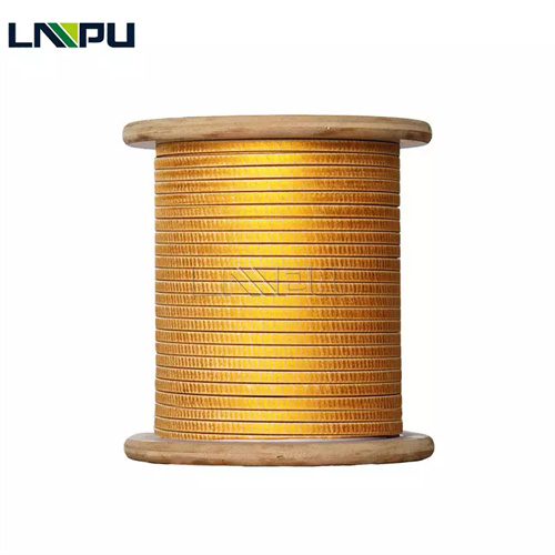
Fiberglass Covered Wire (FGCW) utilizes a multi-layer dielectric composite structure of conductor, enamel coating, glass fiber, and impregnation varnish to provide inductors and coils with comprehensive improvements in heat resistance, dielectric properties, mechanical properties, and heat dissipation. This article, based on standards and specifications such as ANSI/NEMA MW 1000-2018, IEC 60317-48, IEC 62024-1, and IEEE 393, discusses this topic from four dimensions: insulation system, technical requirements, application scenarios, and selection evaluation. It primarily serves the design and procurement of typical applications such as power inductors, RF chokes, ignition coils, deflection coils, and EMI filters.
2 Engineering Requirements for Inductor and Coil Winding Insulation
Inductors can be categorized by application into power inductors, RF inductors, common-mode chokes, differential-mode inductors, ignition coils, deflection coils, and resonant coils. The insulation requirements differ significantly between these types.
- **Power Inductors** (DC-DC Converters, PFC Inductors): Handle high ripple currents (tens to hundreds of amperes), hotspot temperatures can reach 130–155 °C, requiring low loss and high heat dissipation; – **RF Chokes**: Operating frequencies 1 MHz to several GHz, focusing on distributed capacitance (DCR), self-resonant frequency (SRF), and Q value; – **Common Mode Chokes** (CMC): Used for EMI suppression, handling differential-mode current and common-mode noise superposition, requiring high inter-turn insulation and low leakage inductance; – **Ignition Coils**: Peak voltage 25–40 kV, requiring inter-turn and ground insulation to withstand high voltage surges; – **Deflection Coils** (CRT/TV/Oscilloscopes): Horizontal coil frequency 15–100 kHz, vertical coil 50–60 Hz, requiring thermal shock resistance and mechanical stability; – **Resonant Coils** (Wireless Charging, Inductive Coupling): Q value sensitive, requiring low dielectric loss and stable inductance.
In the aforementioned scenarios, FGCW, through a composite system of “inorganic fiber + organic impregnation varnish,” balances the engineering performance of a single enameled wire and an inorganic ceramic coil, becoming the mainstream winding material for medium-to-high power, high-frequency, and high-reliability inductor devices.
3 Insulation System Composition
The insulation system of FGCW in the inductor and coil consists of the following four layers:
- **Conductor Layer**: Round copper (C11000 / C10100) or round aluminum (1350) is used as the current-carrying medium. For RF inductors and high-frequency chokes, the conductor surface should be smooth and defect-free to reduce high-frequency losses due to the skin effect. The Litz wire (multi-strand insulated fine wire stranded together) uses multiple AWG 38-46 fine wires wound together, each fine wire covered with FGCW; 2. **Base layer enamel coating** (optional): polyurethane (UEW, 130-180 °C), polyester (PEW, 155 °C), polyesterimide (PEI, 180 °C), polyamide-imide (PAI, 220 °C), etc., as basic inter-turn insulation; 3. **Glass fiber capping layer**: Electrical grade E-Glass continuous filament glass yarn is tightly, uniformly, and continuously woven or wound around the conductor or enamel coating, with a dielectric constant of approximately 6.0-6.5 and a volume resistivity of 10¹²-10¹⁴ Ω·m @ 25 °C, providing mechanical protection, dielectric redundancy, and heat dissipation channels; 4. **Impregnated varnish finish:** Polyester, polyimide, silicone, or polyimide impregnating varnishes, after curing, form a dense, hard surface layer that inhibits surface creep, external contaminant adsorption, and enhances mechanical integrity.
According to NEMA MW 41-C Clauses 3.3.8 and 3.3.2, the cladding layer must not crack to expose the underlying bare wire or enamel coating after bending the mandrel from 1d to 15d. This clause has direct implications for processes such as “wound close to the core bobbin” and “wound irregularly shaped cores (E-type, RM-type, PQ-type)”.
4 Core Technical Requirements for Inductors and Coils Using FGCW
4.1 Dielectric Strength and Inter-turn Insulation
Inter-turn voltages in inductors are typically low (several volts to tens of volts), but in applications such as ignition coils, TV deflection coils, and X-ray tube coils, peak inter-turn voltages can reach thousands to tens of thousands of volts. FGCW (Fluorescent Gear Wire) offers a significant advantage over single-enameled wire in terms of inter-turn breakdown voltage. The minimum dielectric breakdown voltage (for 4/0-9.5 AWG) given in NEMA MW 41-C Clause 3.8.4 is as follows:
- Single layer coverage: ≥ 170 V – Double layer coverage: ≥ 315 V – For those with an enamel coating, the breakdown voltage corresponding to that enamel coating should be added.
For the secondary winding of the ignition coil (25-40 kV peak value), a composite structure of double-layer FGCW + multi-layer enamel coating bottom layer is recommended. The breakdown voltage of a single layer can reach 5-10 kV, which is much higher than the 1-3 kV of a single enameled wire.
4.2 Heat Resistance and Thermal Life
The hot spot temperature of an inductor winding is typically limited by the thermal class of the insulation system. Typical thermal class for FGCW:
According to Montsinger’s rule of thumb, for every 10 K decrease in winding temperature, insulation life approximately doubles. FGCW offers greater thermal margin than conventional enameled wire, which has direct engineering value in extending the service life of inductors.
4.3 High-Frequency Characteristics and Distributed Capacitance
RF inductors and resonant coils are sensitive to distributed capacitance and dielectric loss at the operating frequency. The dielectric constant of the FGCW glass fiber layer is approximately 6.0–6.5 (higher than 3.0–4.0 for enamel coating), and its equivalent distributed capacitance is slightly higher than that of a single enameled wire. This can be optimized in engineering by:
- Film-Insulated FGCW (with enamel coating) is used instead of bare wire + glass fiber structure to reduce the overall dielectric constant; – “Segmented winding” and “honeycomb winding” are used in the winding process to reduce interlayer coupling; – For ultra-high frequency (≥ 100 MHz) applications, enameled wire + local dispensing process can be considered as an alternative to FGCW.
4.4 Mechanical Strength and Vibration Resistance
Inductive devices withstand wideband random vibrations of 5–2000 Hz in environments such as automotive, rail transportation, and aviation. The FGCW glass fiber braided layer imparts high radial stiffness and wear resistance to the conductor surface, significantly reducing inter-turn displacement and insulation wear caused by vibration. This characteristic is particularly important for ignition coils and automotive DC-DC inductors.
4.5 Heat Dissipation Performance
Heat dissipation in inductor windings primarily occurs through three paths: internal heat conduction within the conductor, heat conduction between insulation layers, and convection and radiation. The FGCW glass fiber layer has a thermal conductivity of approximately 1.0 W/(m·K) (higher than 0.2 W/(m·K) of enamel coating), and combined with the tight contact between the impregnated varnish curing layer and the magnetic core frame, it forms a relatively efficient heat dissipation channel. For high power density inductors (e.g., ≥ 50 W/in³), FGCW can reduce temperature rise by 8–15 K compared to enameled wire.
4.6 Long-term reliability and anti-aging properties
The long-term reliability of inductors is affected by multiple factors, including insulation aging, core aging, and solder joint fatigue. According to IEEE 393, accelerated life testing of inductors should be conducted at the highest operating temperature for ≥ 1000 hours, assessing indicators such as insulation resistance, inter-turn short circuit, and inductance drift. For FGCW, the insulation resistance degradation after accelerated thermal aging testing (155 °C / 1000 h) typically does not exceed 20% of the initial value.
5 Typical Application Scenarios
5.1 Power Supply Inductor and PFC Inductor
Energy storage inductors and boost inductors in switching power supplies (SMPS) and power factor correction (PFC) circuits withstand tens to hundreds of amperes of ripple current, operating at frequencies from 20 kHz to 1 MHz. The multilayer dielectric structure and high heat dissipation characteristics of FGCW make it a preferred choice for medium- to high-power power supply inductors. Typical structure: round wire AWG 18-24, F-grade double-layer FGCW, impregnated with H-grade polyester imide varnish.
5.2 RF Chokes and Inductors
RF chokes operate from 1 MHz to several GHz and are used to block high-frequency AC components. In this scenario, FGCWs need to control distributed capacitance and Q-value attenuation. Typical application: AWG 30-36 FGCW round wire wound on a ferrite core (NiZn, MnZn) bobbin, with 5-50 turns, impregnated with polyester varnish.
5.3 Common Mode Choke
A common-mode choke (CMC) is used for EMI suppression, withstanding the superposition of differential-mode operating current (several to tens of amps) and common-mode noise current. The high inter-turn insulation strength and mechanical stability of the FGCW can withstand long-term common-mode noise impact. According to IEC 62024-1, the withstand voltage rating of the automotive Ethernet CMC should meet the requirement of 1500 V AC @ 1 min.
5.4 Automotive Ignition Coil
The secondary winding of an automotive ignition coil needs to withstand a peak voltage of 25-40 kV. A typical structure is a double-layer FGCW (round wire) + epoxy resin vacuum impregnation + silicone rubber outer casing. The core function of the FGCW in this scenario is to provide 5-10 kV single-layer breakdown voltage redundancy, improving the overall high-voltage surge resistance of the winding.
5.5 Deflection Coil
The deflection yoke in CRT monitors, televisions, and oscilloscopes consists of horizontal and vertical coils. The horizontal coil frequency is 15–100 kHz, and the vertical coil frequency is 50–60 Hz. In this application, the FGCW provides comprehensive performance in terms of heat resistance, vibration resistance, and long-term stability. Typical structure: F-grade single-layer FGCW (round wire), impregnated with polyester enamel.
5.6 Wireless Charging Resonant Coil
Wireless charging (Qi standard, A4WP standard) requires transmitting and receiving resonant coils operating at 100–205 kHz, demanding high Q values (≥ 100) and low dielectric loss. FGCW combined with a Litz wire structure (multi-strand AWG 38–46 fine wire twisted together) can effectively suppress skin effect and proximity effect, improving system transmission efficiency.
5.7 Industrial Induction Heating Coils
Industrial induction heating coils operate from 1 kHz to hundreds of kHz, withstanding high currents (hundreds to thousands of amperes) and high temperatures. In this scenario, the FGCW serves as the winding insulation medium for high-frequency, high-current coils, working in conjunction with water-cooling or air-cooling systems to enable continuous industrial production.
6 Key Points for Selection and Evaluation
The selection of FGCWs for inductors and coils should be comprehensively evaluated from five dimensions: conductor specifications, insulation structure, operating frequency, thermal rating, and process compatibility. Regarding the conductor, for DC and low-frequency (≤ 1 kHz) applications, a single FGCW round wire (AWG 18-30) can be selected; for high-frequency (≥ 100 kHz) applications, a Litz wire structure (multi-strand AWG 38-46 fine wire stranded together) should be preferred, with each fine wire covered with FGCW to suppress the skin effect. Regarding insulation structure, inductors with inter-turn voltage ≤ 100 V can use a single-layer FGCW; those with inter-turn voltage 100–1000 V (such as ignition coils, TV deflectors) should use a double-layer FGCW or a Film-Insulated FGCW + glass fiber composite structure; those with inter-turn voltage ≥ 1 kV (such as the secondary side of ignition coils, X-ray coils) should use a composite system of double-layer FGCW + multi-layer enamel coating + vacuum impregnation. In terms of operating frequency, applications ≤ 1 MHz are not sensitive to the distributed capacitance of the FGCW, and a high thermal class structure can be preferred; applications ≥ 10 MHz should pay attention to the effect of the FGCW dielectric constant on the self-resonant frequency (SRF), and a low dielectric constant enamel coating should be selected if necessary. Regarding thermal class, select F-class (155 °C), H-class (180 °C), or C-class (220 °C) FGCW based on the actual operating temperature and lifespan requirements of the inductor. In terms of process compatibility, FGCW should be able to withstand processes such as winding tension, core frame extrusion, impregnation and curing, without delamination or insulation damage.
At the testing and verification level, suppliers should be able to provide type test reports conforming to standards such as ANSI/NEMA MW 1000, IEC 60317 series, GB/T 7672, IEC 62024-1, and IEEE 393, and possess the following specific test data: dielectric breakdown voltage (25 °C and high temperature), Q value versus frequency curve, self-resonant frequency (SRF), temperature rise characteristic curve, and accelerated thermal aging data. UL, REACH, RoHS, ISO 9001/14001/45001 certifications are used to ensure compliance with design inputs and market access requirements.
7 Frequently Asked Questions
Q1: Does FGCW have any advantages in low-frequency (≤ 1 kHz) inductors?
The main advantages of FGCW in low-frequency applications are high thermal class, good mechanical strength, and excellent vibration resistance. Low-frequency inductors (such as power frequency inductors and audio inductors) are not sensitive to distributed capacitance, so the disadvantage of FGCW’s high dielectric constant is not significant. In high-power power frequency inductors (power reactors and filter inductors), the heat resistance and mechanical advantages of FGCW are particularly prominent.
Q2: How do FGCW and Litz wire structures work together?
Litz wire is composed of multiple AWG 38-46 fine enameled wires twisted together, each wire being independently insulated. In high-frequency (≥ 100 kHz) applications, using multiple wires in parallel can effectively suppress skin effect and proximity effect. When additional heat or mechanical protection is required, each wire can be wrapped with FGCW (forming a Fiberglass-Insulated Litz Wire). However, it should be noted that FGCW has a high dielectric constant, which increases the equivalent distributed capacitance of the Litz wire; therefore, its use in ultra-high frequency (≥ 100 MHz) applications should be approached with caution.
Q3: Will the Q value of an inductor wound with FGCW decrease?
At operating frequencies below 1 MHz, the Q value of FGCW-wound inductors is comparable to that of enameled wire inductors. In the 1–100 MHz band, the higher dielectric constant of FGCW leads to increased distributed capacitance, and the Q value may be 10%–20% lower than that of enameled wire inductors. In the ≥100 MHz band, it is recommended to prioritize single-strand enameled wire winding to avoid the additional dielectric losses introduced by FGCW.
Q4: Is FGCW suitable for high-frequency {transformers}?
Applicable to high-frequency transformers (switching power supply transformers, driver transformers, isolation transformers) operating between 20 kHz and 1 MHz, which withstand high dv/dt. In this scenario, the FGCW serves as the insulating medium between the primary and secondary windings, effectively suppressing partial discharge and inter-turn short circuits. According to IEC 61558, the withstand voltage rating of the high-frequency isolation transformer should meet the 4 kV AC @ 1 min (reinforced insulation) test.
Q5: What are the specific applications of FGCW in ignition coils?
The secondary winding of an automotive ignition coil needs to withstand a peak voltage of 25–40 kV. A typical FGCW application is a double-layer FGCW (AWG 28–36) with a polyamide-imide (PAI, 220 °C) enamel coating impregnated with epoxy or polyester resin using a vacuum impregnation process. A single-layer FGCW has a breakdown voltage of 5–10 kV, while a double-layer FGCW can reach 10–20 kV, meeting the high-voltage insulation requirements of the ignition coil secondary winding.
Q6: Is an impregnation process required after FGCW inductors are wound?
Impregnation is strongly recommended. The FGCW fiberglass layer has a woven structure with minute gaps. Filling these gaps with an impregnation varnish (polyester, polyimide, silicone, polyimide) creates a dense, gap-free insulator, increasing inter-turn breakdown voltage by 30%–50%, while also enhancing mechanical integrity and heat dissipation. Impregnation processes include vacuum pressure impregnation (VPI) and atmospheric pressure impregnation; the former is suitable for high-voltage applications, while the latter is suitable for conventional inductor devices.
Q7: How does the cost of FGCW wound inductors compare to that of enameled wire?
Based on the 2026 commodity market trends, FGCW costs approximately 30%–80% more than conventional polyester enameled wire (UEW/PEW). The main differences stem from the raw material cost of the fiberglass yarn and the equipment investment and labor time required for the weaving process. The reliability benefits of FGCW (1.5–2 times longer lifespan, over 50% lower failure rate, and improved heat dissipation) typically justify the cost premium, especially in automotive-grade (AEC-Q200), industrial-grade, and high-reliability scenarios.
Q8: How suitable is FGCW in wireless charging coils?
This solution is suitable for and is the mainstream solution for high-power (≥ 15 W) wireless charging. The wireless charging operating frequency is 100–205 kHz and is sensitive to Q-value. The FGCW combined with the Litz wire structure effectively suppresses the skin effect. A single thin AWG 40–46 wire with an FGCW outer layer for protection is a typical structure for the transmitting and receiving coils in automotive-grade wireless charging (50 W and above).
Q9: What are the process considerations when winding inductors using FGCW?
Key process considerations include: ① The winding tension should be controlled at 10%–15% of the conductor’s breaking strength to prevent the fiberglass layer from breaking; ② When winding the core frame, ensure that the FGCW fits tightly without loosening or protrusion; ③ The impregnation varnish should fully penetrate the gaps in the fiberglass layer, and there should be no air gaps after curing; ④ The impregnation curing temperature should not exceed the thermal class of the FGCW impregnation varnish; ⑤ The fiberglass layer should not be damaged during lead wire soldering, and it is recommended to use a fiberglass sleeve for secondary protection in the soldering area.
Q10: What is the global supply chain situation for FGCW wound inductors?
FGCW’s global supply chain is concentrated in China, Europe, and North America. Major domestic suppliers include companies like Zhengzhou LP Industry, which have over 30 years of experience in exporting magnetic wire. Their mainstream product specifications cover round wire (0.016–7.0 mm thick), flat wire (0.8–10 mm thick, 2–25 mm wide), and thermal class 155–240 (full range). Certification systems include ISO 9001/14001/45001, UL, REACH, RoHS, and AEC-Q200 (automotive grade optional). Major European suppliers include MWS Wire. In the North American market, Essex Furukawa and Rea Magnet Wire are the mainstream suppliers. When selecting a supplier, buyers should focus on the completeness of the supplier’s type test reports and their high-frequency characteristic testing capabilities.
8 Conclusion
The application of fiberglass covered wire in inductors and coils is essentially an engineering choice for an insulation system that balances multiple objectives: heat resistance, dielectric properties, mechanical properties, heat dissipation, and high frequency performance. When the heat resistance, mechanical properties, and heat dissipation performance of a single enameled wire cannot meet the requirements in scenarios such as power inductors, ignition coils, automotive inductors, and EMI filters, FGCW provides a comprehensive performance leap through its multi-layer dielectric composite structure.
In the selection and evaluation process, engineers are advised to adopt a five-step approach: “Conductor specifications → Insulation structure → Operating frequency → Thermal rating → Process compatibility,” and implement the technical requirements item by item in conjunction with specific application conditions (current, frequency, temperature rise, vibration, and lifespan requirements). For new model development, it is recommended to complete Q-value-frequency curves, temperature rise characteristics, and accelerated thermal aging tests during the prototype stage to ensure that the design margin is consistent with the engineering expectations for service life.
Contact Information:
- E-mail: office@cnlpzz.com
- WhatsApp: 0086-19337889070
- Zhengzhou LP Industry Co., Ltd.