


1 Introduction
High-voltage equipment encompasses typical applications such as power transformers with rated voltages of 3 kV and above, high-voltage motors, GIS instrument transformers, electrostatic precipitators, and X-ray and accelerator magnet coils. In the winding insulation design of such equipment, the conductor surface electric field is concentrated, the partial discharge (PD) threshold is low, and the insulating medium is subjected to long-term electro-thermal-mechanical multi-stress coupling—traditional single-enameled wires struggle to simultaneously ensure heat resistance, dielectric and mechanical reliability.
Fiberglass Covered Wire achieves a synergistic improvement in thermal class, dielectric strength, and mechanical toughness through its multi-layer dielectric composite structure (conductor—enamel coating—glass fiber—impregnating varnish). It has been systematically applied in applications such as stators of 6 kV and above high-voltage motors, oil-immersed power transformer windings, and secondary coils of high-voltage instrument transformers. This article discusses FGCW from four dimensions: insulation system, technical requirements, typical applications, and selection evaluation, based on standards and specifications such as ANSI/NEMA MW 1000-2018, IEC 60317-48, IEC 60076-14, and GB/T 7672.
Compared to the motor winding articles published on June 15, 2026, this article focuses on issues unique to high-voltage equipment, such as electric field strength, impulse voltage, PD suppression, and VPI process compatibility. It aims to provide a complete technical reference for high-voltage winding design engineers, transformer/high-voltage motor purchasers, and magnet wire supplier process engineers.
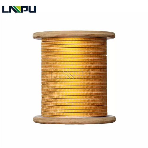
2 Insulation System Composition
The insulation system of FGCW in high-voltage equipment consists of the following four layers:
- **Conductor Layer**: Round copper (T2 / TU1) or round aluminum (1350 / 1370) as the current-carrying medium. The round wire typically covers the AWG 4/0–30 range, while the rectangular wire thickness is generally between 0.8–10 mm and the width between 2–25 mm, depending on the slot fill factor or window utilization and electric field distribution requirements; 2. **Bottom Layer (Enamel Coating)** (Optional): Polyester imide (PEI), polyamide imide (PAI), etc., with an enamel coating grade not lower than 130, providing basic electrical insulation; 3. **Glass Fiber Cover Layer**: Electrical grade E-Glass continuous filament glass yarn is tightly, uniformly, and continuously woven or wound around the conductor or enamel coating, with a dielectric constant of approximately 6.0–6.5 and a volume resistivity of 10¹²–10¹⁴ Ω·m @ 25 °C, providing mechanical protection and dielectric redundancy; 4. **Impregnated varnish finish:** Polyester, polyimide, silicone, or polyimide impregnating varnishes, after curing, form a dense, hard surface layer that inhibits surface creep and external contaminant adsorption.
According to NEMA MW 41-C Clauses 3.3.8 and 3.3.2, the cladding layer must not crack to the point of exposing the underlying bare wire or enamel coating after bending the mandrel from 1d to 15d. This clause directly corresponds to the mechanical reliability requirements in the high-voltage winding embedding and shaping processes. NEMA MW 1000-2018 explicitly states that the synergistic use of the glass fiber cladding layer and the impregnating enamel is a key reason why FGCW is classified separately (Part 48) in the IEC 60317 system—these two layers provide a balance of engineering performance between enameled wire and paper-insulated wire.
3 Core Technical Requirements for High-Voltage Equipment Using FGCW
3.1 Dielectric Strength of Fiberglass Covered Wire
Dielectric strength is the primary performance indicator for FGCW used in high-voltage equipment. NEMA MW 41-C Clause 3.8.4 provides the minimum dielectric breakdown voltage (taking 4/0-9.5 AWG as an example):
- Single layer coverage: ≥ 170 V – Double layer coverage: ≥ 315 V – For those with an enamel coating, the breakdown voltage corresponding to that enamel coating should be added.
For 6 kV and above high-voltage equipment, relying solely on a single-layer FGCW is insufficient to meet the requirements for power frequency withstand voltage and impulse voltage. In engineering practice, a composite insulation process of “double-layer FGCW + vacuum pressure impregnation (VPI)” is often adopted. According to IEC 60076-14 Clause 6.3, the insulation of power transformer windings should be able to withstand short-time power frequency withstand voltage of 1.5 to 2.0 times the rated voltage and full-wave lightning impulse of 1.5 times the rated voltage. The multi-layer dielectric structure of FGCW has direct engineering value in improving the main insulation and longitudinal insulation margin of the winding.
From the perspective of electric field distribution, significant field strength concentration occurs at the ends and slot openings of the high-voltage winding. The series dielectric composed of the glass fiber layer and the impregnated enamel layer in the FGCW has an equivalent dielectric strength higher than that of a single enamel coating or a single paper-sheathed structure. In 10 kV equipment, the VPI process can increase the power frequency breakdown voltage of the FGCW winding by 30%–50% compared to the unimpregnated state, while significantly reducing the probability of phase dynamometer (PD) initiation.
3.2 corona resistant and resistance to partial discharge
Under high-voltage electric fields, ionization and charge accumulation easily occur at the conductor-insulator interface, triggering corona discharge (PD). Long-term PD will lead to electrical treeing breakdown of organic insulating materials. Electrical treeing is one of the main failure modes of high-voltage organic insulation. Its formation mechanism is as follows: high-energy electrons and active groups generated by PD gradually destroy the organic molecular chains, forming micron-sized dendritic conductive channels, ultimately leading to insulation breakdown. FGCW inhibits PD through the following mechanism:
- The glass fiber layer is an inorganic material with strong resistance to electrical dendrite formation; – The interface between the glass fiber and the enamel coating forms a multilayer dielectric structure, and the energy of the PD is gradually attenuated as it propagates along the interlayer; – When used in conjunction with a corona-resistant impregnation varnish (such as silicone or polyimide), it can significantly extend the insulation life.
According to IEC 60270, the high-voltage winding should pass a partial discharge test at 1.5–2.0 times the rated voltage (apparent discharge ≤ 10 pC) before leaving the factory. More stringent engineering requirements are: PDIV (PD initiation voltage) ≥ 2.5 times the rated voltage, and PDEV (PD extinction voltage) ≥ 1.5 times the rated voltage. FGCW, combined with VPI process and corona-resistant varnish, can reliably meet these requirements.
3.3 Heat Resistance and Thermal Life
The operating temperature of high-voltage equipment windings is typically in the range of Class F (155 °C) to Class H (180 °C), while traction and metallurgical equipment can reach Class C (220 °C). Typical FGCW thermal class:
According to Montsinger’s rule of thumb, insulation life approximately doubles for every 10 K decrease in winding temperature. FGCW offers a higher thermal margin than conventional enameled wire, which has direct engineering value in extending the service life of high-voltage equipment. In H-class and higher applications, the thermal life advantage of FGCW compared to enameled wire can be 2-3 times greater.
The hotspot temperature rise of high-voltage equipment windings is typically the ambient temperature + average winding temperature rise + 10-15 K. During design, a thermal margin of ≥ 10 K must be reserved within the temperature rise limits specified in IEC 60034-1 to cope with sudden overloads, harmonic currents, and cooling system degradation.
3.4 Mechanical Strength
High-voltage equipment windings are subjected to complex mechanical stresses during manufacturing and operation, including bending and stretching during winding and shaping, friction and compression from end binding, electromagnetic vibration at twice the power supply frequency during operation, and the short-circuit electrodynamic impact unique to transformer windings. The peak short-circuit electrodynamic force can reach 25–49 times the electromagnetic force corresponding to the rated current (estimated based on 4%–20% of the short-circuit impedance), imposing stringent requirements on the radial and axial stiffness of the windings. FGCW’s glass fiber braided layer imparts high radial stiffness and wear resistance to the conductor surface, significantly reducing the engineering risk of enamel coating damage during manufacturing.
3.5 Oil resistance and moisture resistance
Oil-immersed power transformers use mineral oil as the insulation and cooling medium, requiring the winding insulation to have long-term oil resistance. Glass fiber, an inorganic material, is chemically inert to mineral oil, synthetic ester oil, and silicone oil. Combined with an oil-resistant impregnation varnish curing layer, FGCW can operate stably at an oil temperature of 105 °C for extended periods without significant degradation of its dielectric properties. This characteristic makes FGCW suitable for applications such as oil-immersed transformers, high-voltage oil-immersed reactors, and oil-immersed instrument transformers.
It is particularly important to note that the moisture resistance of the impregnated varnish finish is crucial when the FGCW is used outdoors or in humid environments. According to IEC 60076-22, outdoor oil-immersed transformer windings should pass a 144-hour damp heat cycling test, and the cured varnish layer should show no blistering, delamination, or significant degradation of dielectric properties.
3.6 Thermal shock resistance and crack resistance
Under conditions such as high-voltage equipment startup, sudden load changes, and reclosing after a short circuit, the winding temperature can change drastically within seconds to minutes, ranging from 50 to 100 K. FGCW, through its glass fiber skeleton, disperses thermal stress, and its coefficient of linear expansion is significantly lower than that of a pure enamel coating system (approximately 5 × 10⁻⁶ / K vs. 60–100 × 10⁻⁶ / K), effectively suppressing insulation cracking and blistering under thermal cycling.
4 Typical Application Scenarios
4.1 High-voltage motor stator winding
The stator windings of high-voltage motors with a rated voltage of 6 kV and above (large fans, water pumps, compressors, rolling mills drive motor) must withstand high phase voltages and impulse voltages (dV/dt). A typical structure is “F-grade (H-grade) double-layer glass-insulated enameled flat copper wire + vacuum pressure impregnation (VPI)”. According to GB/T 11021, the thermal life of the high-voltage motor stator windings should meet the design service life requirements (e.g., 20 years).
The voltage level of the high-voltage motor and the selection of the FGCW structure have the following correspondence:
4.2 Power transformer winding
For 110 kV and above oil-immersed power transformer windings, FGCW (copper or aluminum) is used in conjunction with Nomex paper or polyester film as an additional insulation layer. The core functions of FGCW in this scenario are: resistance to long-term mineral oil corrosion, improvement of longitudinal insulation strength, and reduction of the risk of mechanical damage under short-circuit electrodynamic forces.
For power distribution transformers (10-35 kV), single-layer FGCW (round wire) or rectangular wire can be used, combined with conventional insulating paper and mineral oil to achieve a compact and low-cost insulation design. FGCW has a significant advantage over enameled wire in terms of short-circuit electrodynamic resistance.
4.3 High Voltage Transformers and Bushings
In components such as the secondary windings of current transformers (CTs) and voltage transformers (PTs), and bushing conductors, FGCW (Fused Gas Chloride Winding) is used to improve insulation margin and withstand voltage fluctuations (PDs). According to IEC 61869, the secondary windings of current transformers must meet both power frequency withstand voltage and impulse voltage requirements. The internal insulation of bushing-type equipment typically employs a capacitor bank structure wound with FGCW, achieving electric field homogenization through the alternating arrangement of multiple conductive layers and insulation layers.
4.4 Special High-Voltage Equipment
Electrostatic precipitators (ESPs) high-voltage electrodes, X-ray tube high-voltage transformers, accelerator magnet coils, laser high-voltage power supplies, and other applications require stringent insulation withstand voltage ratings (≥ 30 kV DC or higher), long-term stability, and geometric precision. FGCW (rectangular wire) or round wire is used as the primary insulation medium for high-voltage windings in these devices.
4.5 Output Reactor of High Voltage Frequency Converter
In medium- and high-voltage variable frequency drive (6 kV/10 kV) systems, the output reactors and filter windings withstand high-frequency du/dt surges (typically 5–10 kV/μs) from PWM output. The multilayer dielectric structure of the FGCW (Fluorescent Gas Shielding Wrapper) is highly effective in suppressing partial discharge and surface creepage. In medium- and high-voltage variable frequency drive scenarios, the FGCW is typically used in conjunction with a semi-conductive shielding layer to balance the electric field distribution and reduce the surface electric field gradient.
5 Key Points for Selection and Evaluation
The selection of high-voltage power-displacement windings (FGCWs) should be comprehensively evaluated from four dimensions: conductor material, geometric specifications, insulation structure, and testing and verification. Regarding conductors, copper (T2/TU1) is superior due to its high conductivity and low contact resistance, making it suitable for high-power-density windings; aluminum (1350/1370), with its lightweight and cost advantages, is suitable for large-size oil-immersed transformer windings. In terms of geometric specifications, round wires typically cover the AWG 4/0–30 range, while rectangular wires generally have a thickness of 0.8–10 mm and a width of 2–25 mm, depending on slot fill factor or window utilization and electric field distribution requirements. For insulation structure, the selection of single-layer/double-layer FGCWs requires a comprehensive evaluation considering power frequency withstand voltage, impulse voltage, and the feasibility of VPI (Voltage-Insulated Pipeline) technology; whether to install a film-insulated underlayer is related to dielectric redundancy and cost. In the impregnation system, polyester and polyesterimide correspond to F grade, polyimide can cover H grade and above, while silicone and polyimide are suitable for C grade high temperature and corona resistant scenarios.
At the testing and verification level, suppliers should be able to provide type test reports conforming to standards such as ANSI/NEMA MW 1000, IEC 60317 series, GB/T 7672, and IEC 60076-14, and possess the following high-voltage specific test data: Power Frequency Withstand, Lightning Impulse (1.2/50 μs), Switching Impulse (250/2500 μs), Partial Discharge Initiation Voltage (PDIV), and Extinction Voltage (PDEV). UL, REACH, RoHS, and ISO 9001/14001/45001 system certifications are used to ensure compliance with design inputs and market access requirements.
5.1 Process Compatibility
The performance of high-voltage FGCWs under VPI processes is an important consideration in selection. The requirements of the VPI process for FGCWs include:
- The fiberglass braided layer should be able to withstand vacuum impregnation (≤ 100 Pa) and pressure impregnation (0.3-0.6 MPa) cycles without delamination or blistering; – The impregnating varnish should be able to fully penetrate the gaps between the fiberglass layers, forming a dense, air-gap-free insulator after curing; – The fiberglass coverage (≥ 95%) and braiding uniformity should meet the process consistency requirements to avoid missing wraps or localized looseness.
5.2 Aging Assessment
The design life of high-voltage equipment windings is typically 20-40 years, and insulation aging assessment is a crucial step in selection and verification. Common methods include:
- Accelerated thermal aging test: Long-term aging is carried out at ≥ 3 temperature points according to IEEE 1776 / IEC 60216, and the design life is extrapolated from the Arrhenius curve; – Combined electrothermal aging: Combined testing at rated voltage and high temperature to simulate actual working conditions; – Oil immersion compatibility test: The oil-immersed transformer winding shall be subjected to a compatibility test at an oil temperature of 105 °C for ≥ 168 hours to assess the impact of FGCW impregnation varnish on the dielectric properties of the oil.
6 Frequently Asked Questions
Q1: Is FGCW necessary in high-voltage equipment above 6 kV?
While not absolutely necessary, engineering practice has proven its significant engineering value. For high-voltage motors and transformers operating at voltage levels of 6 kV and above and undergoing long-term continuous operation, FGCW offers superior overall performance in terms of dielectric margin, dielectric constant (PD) resistance, and oil resistance compared to single enameled wire, making it the mainstream technical solution.
Q2: How should I choose between single-layer and double-layer FGCW?
The design should be determined based on the rated voltage and impulse voltage level. Generally, equipment with a rated voltage below 6 kV can use a single-layer FGCW; equipment with a rated voltage of 6-10 kV is recommended to use a double-layer FGCW; and equipment with a rated voltage above 10 kV should have a double-layer FGCW with additional mica tape or polyester film wrapping. The design should be verified through electric field simulation and prototype testing.
Q3: Can FGCW completely replace mica tape insulation?
It cannot be directly substituted. Mica tape, as the main insulating medium for high-voltage motor stators, has a corona resistant and electrical dendrite suppression capability that FGCW cannot match. In high-voltage windings, FGCW typically forms a “composite insulation” system with mica tape and polyester film—FGCW provides bar insulation, while mica tape provides slot and end insulation.
Q4: What are the breakdown voltage test standards for the high-voltage winding FGCW?
According to Clause 4 of IEC 60851-5, the breakdown voltage test for magnet wire shall be conducted separately at 25 °C and 155 °C (or other specified temperatures). The supplier shall provide breakdown voltage distribution data at each temperature, and the P95 probability value shall not be lower than the standard requirement. For FGCWs used in high-voltage equipment, breakdown voltage data after VPI processing (impregnation + curing) shall also be provided to reflect the dielectric performance under actual operating conditions.
Q5: How suitable is FGCW for variable frequency drive of high-voltage motors?
Applicable. The high-frequency du/dt impulse voltage output of PWM inverter places special requirements on winding insulation. The multi-layer dielectric structure of FGCW, combined with corona resistant impregnation varnish, has a significant effect on suppressing partial discharge and electrical treeing, making it one of the mainstream solutions for stator windings of medium and high voltage variable frequency motors.
Q6: What indicators should be given special attention in FGCW quality evaluation for high-voltage applications?
In addition to conventional dielectric breakdown voltage, thermal level, and mechanical flexibility, high-voltage applications also require attention to: ① Glass fiber coverage (should be ≥ 95% to avoid missing packages); ② PD suppression capability of the impregnating varnish (apparent discharge ≤ 5 pC @ 2 kV); ③ Temperature coefficient of breakdown voltage (degradation rate at high temperatures); ④ Compatibility with VPI process (no delamination or bubbling of the insulation layer during vacuum impregnation).
Q7: Will the dielectric properties of the FGCW winding degrade after long-term operation in an oil-immersed transformer?
Under compliant processes, the dielectric performance degradation of FGCWs after 20-30 years of oil-immersion operation typically does not exceed 15%-20% of the initial value. The degradation mainly originates from: ① slow thermal oxidation of the impregnating varnish; ② erosion of the enamel coating interface by trace amounts of moisture and acidic substances in the mineral oil. By selecting polyester imide or polyimide impregnating varnishes with excellent oil resistance, and in conjunction with online oil monitoring (DGA, oil dielectric loss), the actual lifespan of FGCW windings can be extended to over 30 years.
Q8: Is FGCW suitable for DC high-voltage equipment (such as HVDC converters)?
Applicable, but attention should be paid to the space charge effect under a DC electric field. The internal electric field distribution of the insulation under DC voltage is determined by conductivity (not dielectric constant). Conductivity mismatch between layers in the FGCW multilayer structure may lead to space charge accumulation. It is recommended to use a DC-tested FGCW structure in HVDC applications, and to use it in conjunction with a semiconducting layer or gradient coating to suppress the space charge effect. According to IEC 61378-2, type testing of HVDC commutator windings should include a DC polarity reversal test (±1.0 times rated voltage).
Q9: How much higher are the raw material costs for FGCW compared to enameled wire?
Based on the 2026 commodity market trends, FGCW costs approximately 30%–60% more than conventional polyester/enameled wire. The main differences stem from: ① the raw material cost of glass fiber yarn (E-Glass yarn); ② the equipment investment and labor hours for the weaving process; and ③ the energy consumption of the impregnation and curing process. In high-voltage equipment, the reliability benefits of FGCW (1.5–2 times longer lifespan and over 50% reduction in failure rate) typically far outweigh its cost premium.
Q10: What is the status of FGCW’s supply chain? Who are its main domestic suppliers?
FGCW’s global supply chain is concentrated in China, Europe, and North America. Major domestic suppliers include companies like Zhengzhou LP Industry, which have over 30 years of experience in exporting magnetic wire. Their mainstream product specifications cover round wire (0.016–7.0 mm thick), flat wire (0.8–10 mm thick, 2–25 mm wide), and thermal class 155–240 (full range). Certification systems include ISO 9001/14001/45001, UL, REACH, and RoHS. Major European suppliers include MWS Wire and Synflex. In the North American market, Essex Furukawa and Rea Magnet Wire are the mainstream suppliers. When selecting a supplier, buyers should focus on the completeness of the supplier’s type test reports and their high-voltage specific testing capabilities.
7 Conclusion
The application of FGCW in high-voltage equipment windings is essentially an engineering choice for insulation systems under multi-field coupling conditions including power frequency, impulse, continuous electrical stress, long-term thermal stress, and oil/moisture/vibration environments. When the dielectric margin and mechanical reliability of a single enameled wire cannot meet the requirements of high-voltage engineering, FGCW, through its multi-layer dielectric composite structure, provides a comprehensive performance leap in power frequency withstand voltage, impulse voltage, PD suppression, and oil resistance. Combined with VPI technology, composite insulation design, and rigorous type testing verification, FGCW has gradually become the mainstream technical solution for 6 kV and above high-voltage windings.
In the selection and evaluation process, engineers are advised to adopt a five-step approach: “conductor material → geometry specifications → insulation structure → impregnation system → testing and verification.” This approach combines specific voltage levels, operating conditions, and manufacturing process constraints to implement technical requirements item by item. For new model development or upgrades of existing models, it is recommended to complete PDIV/PDEV measurements, VPI process compatibility verification, and accelerated aging tests during the prototype stage to ensure that design margins and service life are consistent with engineering expectations.
Contact Information:
- E-mail: office@cnlpzz.com
- WhatsApp: 0086-19337889070
- Zhengzhou LP Industry Co., Ltd.