


Modern power electronics inverters are increasingly widely used in photovoltaics, energy storage, electric vehicle drives, and industrial frequency conversion. Their switching frequencies are constantly rising, and power densities are continuously increasing. The resulting electromagnetic compatibility (EMC) issues have become one of the key challenges in system design. Aluminum foil, as a mature, cost-effective, and highly shielding metal material, plays an irreplaceable role in inverter EMC shielding design. This article starts from the physical mechanisms of inverter EMC problems, systematically explaining the working principle of aluminum foil in inverter shielding, material and specification selection, engineering implementation methods, relevant standards, and common design and construction issues.
Electromagnetic Interference Sources of Inverters and the Shielding Role of Aluminum Foil
The core electromagnetic interference source of inverters comes from the high-speed switching action of power semiconductor devices. Devices such as IGBTs, SiC MOSFETs, and GaN HEMTs exhibit voltage change rates (dv/dt) of 5–20 kV/μs and current change rates (di/dt) of 1–5 kA/μs during turn-on and turn-off. These rapid transients generate abundant harmonic components in the main circuit, with the primary energy concentrated in the fundamental frequency and its higher harmonics. For inverters using SPWM or SVPWM modulation, the switching frequency is typically in the range of 2 kHz to 100 kHz, but due to the steep edges of the switching waveform, its spectral components can extend to over 100 MHz.
These high-frequency interferences affect peripheral equipment through three main coupling pathways: conducted coupling propagates outward through power and signal lines; radiated coupling emits into space through near and far fields; and radiation and conduction can also form loops through cables and the chassis. CISPR 11, CISPR 22, and EN 55011, EN 55022 standards specify clear requirements for radiated and conducted emissions limits for inverters in different frequency bands.
The shielding effect of aluminum foil in inverters is mainly reflected in three levels. First, inside the housing, the aluminum foil is bonded to an insulating substrate, covering strong interference sources such as switching power supply modules, IGBT modules, and magnetic components, forming local shielding and suppressing near-field radiation interference to sensitive circuits. Second, at cable and connector entry points, the aluminum foil is used in conjunction with braided layers or aluminum foil Mylar composite tape to provide a 360° low-impedance termination path for the shielding layer. Third, at the overall housing level, the aluminum foil, as a conductive lining or tape, covers weak points in the housing such as seams, openings, and ventilation holes, compensating for the inability of mechanical structures to achieve perfect sealing.
Physical Basis of Aluminum Foil Shielding
The shielding effectiveness of aluminum foil mainly comes from three mechanisms: reflection loss, absorption loss, and multiple reflection loss. Under far-field plane wave incidence, the overall shielding effectiveness can be described by the Schelkunoff formula: SE = R + A + B, where R is the reflection loss, A is the absorption loss, and B is the multiple reflection correction term.
The reflection loss R is related to the relative conductivity and relative permeability of the material, and is approximately expressed as R ≈ 50 + 10·log(ρ·f) + 10·log(μ_r/σ_r) (far-field, electric field wave). Aluminum has approximately 61% the conductivity of copper and a relative permeability of 1; therefore, for non-magnetic metals, the difference in reflection loss between aluminum and copper is mainly determined by conductivity. Above 1 MHz, reflection loss dominates, and the difference in shielding effectiveness between aluminum foil and copper foil gradually decreases.
The absorption loss A is proportional to the material thickness, permeability, and the square root of the frequency: A ≈ 1.7·t·√(f·μ_r·σ_r) (dB). This means that for a given metallic material, the absorption loss increases with increasing frequency. Skin depth δ = 1/√(π·f·μ·σ) characterizes the depth at which an electromagnetic wave attenuates to 1/e (approximately 37%) of its surface value in a metal. The skin depth of aluminum at different frequencies is approximately 12 mm at 50 Hz, approximately 2.7 mm at 1 kHz, approximately 0.84 mm at 10 kHz, approximately 84 μm at 1 MHz, approximately 27 μm at 10 MHz, and approximately 8.5 μm at 100 MHz. Understanding this parameter is crucial for selecting the minimum thickness of the aluminum foil: absorption efficiency exceeding 95% can be achieved when the aluminum foil thickness is greater than approximately 3 times the skin depth.
The multiple reflection correction term B becomes significant when the shielding layer thickness is less than the skin depth and is a non-negligible term for thin aluminum foil applications. When the aluminum foil thickness is greater than one skin depth, B is generally negligible.
Main Application Scenarios of Aluminum Foil in Inverters
Housing lining shielding is one of the typical applications of aluminum foil in inverters. Inverter housings are typically made of aluminum alloy or galvanized steel, but plastic or composite housings are used in cost-sensitive or weight-reduction applications. Plastic housings lack electromagnetic shielding capabilities and must be internally coated with a conductive coating or fitted with aluminum foil to create a shielding layer. 3M 1170 series aluminum foil tape is a representative product for this application, offering typical shielding effectiveness of over 85 dB in the 1 MHz to GHz band, a rated voltage of 600 V, an operating temperature range of -40 °C to 130 °C, and a flame retardant rating meeting UL 510 standards.
Cable shielding termination is another critical application. Inverters connect to motors, power grids, and loads via shielded cables. The shielding layer must be terminated with a 360° low-impedance termination at the point of entry into the housing; otherwise, a “pigtail effect” will occur at the termination point, reducing shielding effectiveness by 20–30 dB. Aluminum foil tape is often used to assist in securing the shielding termination clips and expanding the contact area. Aluminum foil Mylar (AL-PET) composite tape is a more common shielding material in cable manufacturing. Its thickness is typically above 6.5 μm, and its width is 300–1000 mm, conforming to national standards such as GB/T 3198-2010.
Magnetic shielding of transformers and inductors is also a potential application of aluminum foil. Stray magnetic fields around high-frequency transformers, common-mode inductors, and differential-mode inductors in inverters can be shielded by aluminum foil, but for low-frequency magnetic fields, aluminum foil, like non-magnetic materials, has limited effectiveness.
EMI treatment of heat sinks is an easily overlooked aspect. Power modules in inverters are usually mounted on large-area aluminum heat sinks, and there may be electrical gaps between the heat sink and the chassis. The levitation of the heat sink can act as a radiating antenna. Reliably grounding the heat sink with aluminum foil or copper braided tape can significantly reduce common-mode radiation.
Aluminum Foil Materials and Alloy Systems
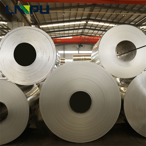
Industrial aluminum foil mainly uses several series, including 1xxx series (industrial pure aluminum), 3xxx series (aluminum-manganese alloy), and 8xxx series (aluminum-iron alloy). 1xxx series aluminum foil has an aluminum content of no less than 99.0% and an electrical conductivity of approximately 61% IACS, making it the first choice for shielding applications. 3xxx series aluminum foil has higher strength and is suitable for applications requiring stamping. 8xxx series aluminum foil has a lower cost but slightly lower electrical conductivity.
1060 aluminum foil is a common 1xxx series grade used in shielding applications. It has an aluminum content of no less than 99.6%, an electrical conductivity of approximately 62% IACS, a tensile strength of 70–110 MPa, and an elongation of no less than 20%. This material has good processing performance and can be rolled to thicknesses below 0.006 mm.
3003 aluminum foil is a representative grade of the 3xxx series. It contains approximately 1.2% manganese to improve strength, has an aluminum content of at least 96.7%, an electrical conductivity of approximately 41% IACS, a tensile strength of 130–180 MPa, and an elongation of at least 15%. In applications requiring complex forming or resistance to mechanical stress, 3003 aluminum foil offers superior overall performance compared to 1060.
Surface treatment of aluminum foil significantly impacts long-term reliability. Bare aluminum forms a dense alumina (Al₂O₃) film in the atmosphere. This film has extremely high resistivity but a thickness of only 2–5 nm, having minimal impact on low-frequency conductive contacts and similarly minimal impact on high-frequency shielding, as the skin depth of high-frequency currents is much greater than the oxide layer thickness. The key issue lies in the accumulation of the oxide film at connection points: long-term exposure to humid or corrosive environments causes the oxide layer to thicken continuously, leading to a significant increase in contact resistance.
Coating the aluminum foil surface with a conductive coating is one method to improve contact performance. Copper/nickel composite plating (Cu/Ni composite plating) forms a highly solderable and conductive metallic layer on the surface of aluminum foil, but it is more expensive. Polymer conductive coatings (such as resin coatings filled with silver, copper, or nickel powder) offer a trade-off between cost and performance and are mainly used for shielding in consumer electronics.
Selection of Thickness and Width
The thickness of the aluminum foil used for shielding should be selected based on the interference frequency band and shielding effectiveness requirements. In the 100 kHz to 1 MHz frequency band, the skin depth of aluminum is approximately 84–270 μm, and an aluminum foil thickness of 0.05–0.1 mm (50–100 μm) can provide approximately 30 dB of absorption loss; in the 1 MHz to 10 MHz frequency band, the skin depth decreases to 27–84 μm, and an aluminum foil thickness of 0.05–0.1 mm can provide more than 50 dB of absorption loss; in the 10 MHz to 100 MHz frequency band, the skin depth is 8.5–27 μm, and an aluminum foil thickness of 0.05 mm can provide more than 70 dB of absorption loss.
Commonly used aluminum foil thicknesses in engineering are as follows: 0.025 mm (25 μm) for cable shielding and lightweight EMI tape; 0.05 mm (50 μm) for housing linings, shielding tape, and transformer winding shielding; 0.1 mm (100 μm) for structural shielding and reinforced shielding tape; and thicknesses of 0.2 mm and above, approaching those of aluminum plates, are mainly used for structural shielding and busbar extension.
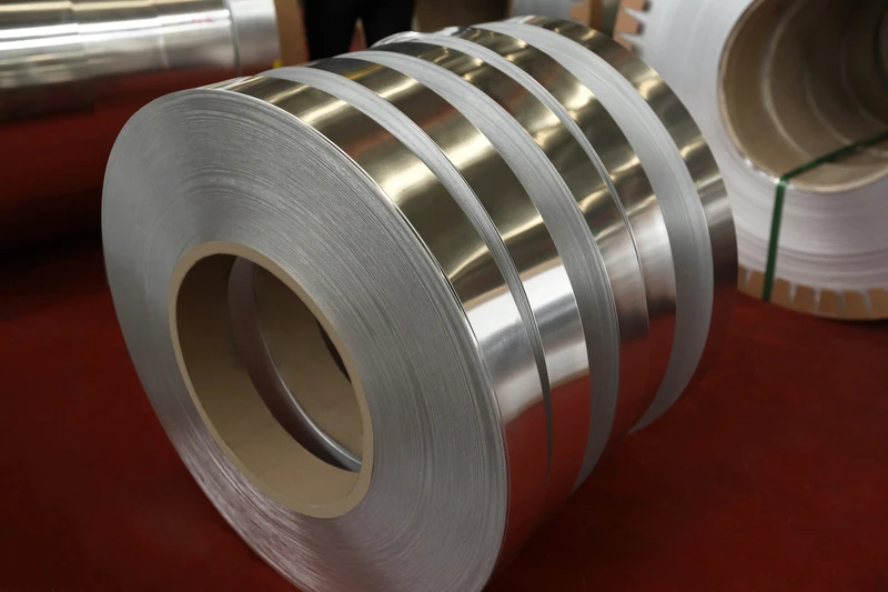
Width selection is primarily based on construction space and coverage continuity. Housing lining shielding typically uses rolls with widths of 300–1000 mm for easy large-area application. Aluminum foil products in tape form (such as 3M 1170) have standard widths of 25 mm, 50 mm, 76 mm, 100 mm, and 150 mm, mainly used for joint treatment and local reinforcement. Transformer and inductor shielding typically uses narrow strips with widths of 10–50 mm, wrapped around the outside of the magnetic core or coil.
Installation Process
There are four main installation methods for aluminum foil: adhesive bonding, mechanical crimping, welding, and conductive adhesive bonding.
Adhesive bonding is the most common method for shielding inner linings of housings. The back of the aluminum foil is coated with acrylic conductive or non-conductive adhesive and adhered to the housing or insulating substrate. Conductive adhesive can form a low-impedance contact between the aluminum foil and the substrate, but it is more expensive; non-conductive adhesive only provides mechanical fixation, and electrical connections need to be established separately through crimping or welding. 3M 1170 aluminum foil tape uses acrylic conductive adhesive, balancing adhesive strength and conductivity.
Mechanical crimping is suitable for connecting aluminum foil thicker than 0.1 mm to metal substrates. Screws or rivets are used with flat washers to fix the aluminum foil to the metal housing. The spacing of the crimping points should be determined according to the aluminum foil thickness and substrate rigidity; for 0.1 mm thick aluminum foil, the spacing should not exceed 100 mm.
Welding provides the highest contact reliability. Aluminum foil can be welded using ultrasonic welding, laser welding, or capacitor discharge welding. Capacitor discharge welding is a common method for connecting aluminum foil to copper terminals. It has a short welding time, a small heat-affected zone, and is suitable for connecting thin aluminum foils. Soldering on aluminum foil presents significant challenges, primarily because the aluminum oxide film continues to form during the welding process, making it difficult to achieve a reliable metallurgical bond with conventional soldering.
Conductive adhesive bonding is suitable for applications where welding or mechanical fixing is not feasible. Epoxy-based or silicone-based conductive adhesives fill metal particles (silver, copper, nickel), forming conductive channels after curing. The contact resistance of conductive adhesives is 5–10 times higher than mechanical crimping, and it is mainly used for auxiliary shielding in the low-frequency range.
Key details during construction include: removing oil, dust, and release agents from the substrate surface before aluminum foil bonding; ensuring the conductive adhesive cures under pressure; maintaining a 10–20 mm overlap at aluminum foil seams to ensure electrical continuity; and avoiding sharp angles and burrs on the aluminum foil edges to prevent point discharge under high voltage or high electric field strength.
Testing and Evaluation of Shielding Effectiveness
There are three main testing methods for aluminum foil shielding effectiveness: near-field method, far-field method, and power method. The near-field method uses a small magnetic field probe or electric field probe to perform local measurements on the outer and inner surfaces of the shielding under test, suitable for evaluating the local shielding effect of actual enclosures. The far-field method uses an antenna in an anechoic chamber to perform overall measurements of the device under test at a far-field distance, and is the method recommended by the CISPR 16 series standards. The power method measures the transmitted power of the material under test in a coaxial transmission line, mainly used for material-level shielding effectiveness evaluation.
For practical engineering evaluation, engineers typically use a relative testing method: measuring the near-field strength of the interference signal at critical locations on the enclosure (such as heat dissipation holes, seams, connector entrances), and then measuring the signal strength at the same location again after adding aluminum foil shielding; the difference between the two measurements represents the actual improvement in shielding effectiveness at that location. The radiated emission limits specified in CISPR 11 and EN 55011 are mandatory requirements for Class A and Class B industrial, scientific, and medical equipment. Inverters that fail these tests cannot enter the market.
Related Standards and Certifications
Inverters and their shielding designs need to comply with multiple EMC standards. CISPR 11 (EN 55011) is the standard for radio frequency emission limits for industrial, scientific, and medical equipment, applicable to industrial inverters; CISPR 22 (EN 55022) is the radio frequency emission limit for information technology equipment, applicable to communication power supplies and server power supplies; CISPR 25 is the standard for ignition disturbance characteristics of internal combustion engines in vehicles, ships, and installations, applicable to automotive inverters; GB/T 17626 series are the electromagnetic compatibility testing and measurement technology standards adopted in China.
At the material level, aluminum foil products need to meet the requirements of GB/T 3198-2010 “Aluminum and Aluminum Alloy Foil” regarding thickness, width, and surface quality; conductive aluminum foil tape needs to comply with UL 510 (polymer adhesive tape) or relevant IEC standards; typical products such as 3M 1170 have passed UL 510 flame retardant certification and RoHS environmental certification.
Common Design and Construction Issues
In actual aluminum foil shielding projects, common design and construction issues mainly fall into the following categories.
Improper seam treatment is the most common problem. If the aluminum foil is not continuously covered at the chassis seams, or is only attached to the surface without forming a low-impedance contact with the chassis, the gaps will become the main channels for electromagnetic leakage. The correct approach is to attach aluminum foil to both sides of the seam, ensuring at least 20 mm overlap and reliable crimping at the overlap.
Poor grounding of the shielding layer is another typical problem. If the aluminum foil shielding is not reliably connected to the main grounding busbar of the chassis, an effective return path cannot be formed, and the shielding effectiveness will be greatly reduced. Grounding should use a short and thick connection method, and the distance between connection points should not exceed 300 mm.
Insufficient aluminum foil thickness is particularly prominent in the low-frequency band. Below 1 kHz, the skin depth of aluminum reaches several millimeters, and aluminum foil with a thickness of only 0.05 mm cannot provide sufficient absorption loss. In this case, it is necessary to use an aluminum plate with a thickness of more than 1 mm or add magnetic materials.
Mechanical damage during construction is also a common cause of shielding failure. If the aluminum foil is scratched, punctured, or wrinkled during the application process, electromagnetic leakage will occur at the damaged points. Aluminum foil with a thickness of less than 0.025 mm requires particular care. During transportation and storage, the aluminum foil should be kept flat, avoiding creases and heavy pressure.
Direct contact between aluminum and copper is another issue that needs attention. In humid environments, aluminum and copper undergo electrochemical corrosion, and the contact resistance increases significantly over time. At the connection points between aluminum foil and copper grounding bars or copper braided strips, copper-aluminum transition joints or tin-plated copper-aluminum composite structures should be used.
Selection Decision Points
The selection of shielding aluminum foil should comprehensively consider the interference frequency band, shielding effectiveness requirements, construction conditions, and cost constraints.
The interference frequency band is the most fundamental constraint. For low-frequency inverters with switching frequencies below 20 kHz, aluminum foil with a thickness of 0.1 mm or more should be selected; for mid-frequency inverters with switching frequencies between 20 kHz and 100 kHz, aluminum foil with a thickness of 0.05–0.1 mm is sufficient; for SiC or GaN inverters with switching frequencies exceeding 100 kHz, aluminum foil with a thickness of 0.025–0.05 mm can provide sufficient shielding effectiveness.
Construction conditions determine the form and installation method of the aluminum foil. For large-area application inside the housing, roll aluminum foil should be selected; for joints and local reinforcement, tape should be used; for transformer and inductor shielding, narrow strip aluminum foil should be selected; for on-site construction where open flames are prohibited, adhesive-bonded aluminum foil should be selected.
Environmental conditions determine the surface treatment. Bare aluminum foil can be used in dry indoor environments; in humid or corrosive environments, aluminum foil with a conductive coating should be selected; in high-temperature environments (continuous operating temperature exceeding 130 °C), specially treated high-temperature aluminum foil or metallized fabric should be selected.
Cost constraints typically favor 1xxx series industrial pure aluminum foil, but 3xxx series aluminum-manganese alloy foil should be chosen for applications requiring complex forming. Increasing the thickness of the aluminum foil significantly increases material costs; therefore, the thinnest foil should be selected while still meeting shielding effectiveness requirements.
Conclusion
As a key material in inverter EMC shielding, the selection of aluminum foil, its thickness determination, installation process, and grounding design must strictly adhere to electromagnetic field theory and relevant standards. Understanding the frequency characteristics of skin depth, reflection loss, and absorption loss is the physical basis for rationally selecting aluminum foil thickness. In practical engineering, the aluminum foil specifications and installation method should be comprehensively determined based on the inverter’s specific interference frequency band, shielding effectiveness requirements, housing structure, and construction conditions. The effectiveness of the shielding design should be ensured through standardized construction processes and systematic EMC testing. Avoiding common design and construction pitfalls and paying attention to joint treatment and grounding reliability are fundamental to ensuring the inverter’s electromagnetic compatibility meets standards.