


Fiberglass-covered magnet wire is a core insulated conductor for windings in F/H/C-class motors, transformers, and household appliances. Its structure constitutes a typical multi-layer composite system: a copper conductor or aluminum conductor—in round wire or flat wire form—serves as the conductor, over which alkali-free E-glass fiber yarn is helically wound to form the reinforced insulation layer (fiberglass covering); this is then impregnated and cured with insulating varnish, forming a composite varnish film, resulting in a dense, mechanically robust magnet wire with thermal class up to 220°C (Class C).
This article disassembles the fiberglass-covered magnet wire structure layer-by-layer—from innermost to outermost—detailing material selection, manufacturing processes, technical specifications, and performance impact of each layer. It serves as a complete technical reference for motor/transformer R&D engineers, procurement personnel, and electrical engineering students.
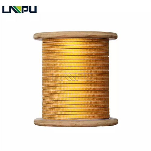
I. Overall Structure Overview of Fiberglass-Covered Magnet Wire
The complete structure of fiberglass-covered magnet wire (from innermost to outermost) comprises five layers:
Layer 1: Conductor — current-carrying core; determines electrical performance; Layer 2: Conductor Surface Treatment — enhances enamel coating adhesion, prevents oxidation, reduces contact resistance; Layer 3: Fiberglass Covering — one of the primary insulation layers; provides mechanical strength and partial electrical insulation; Layer 4: Varnish Film — bonding, filling, and reinforcement; improves dielectric strength and moisture resistance; Layer 5: Outer Surface — smooth, dense, abrasion-resistant final protective layer.
Total insulation thickness (single-side):
- Single-layer fiberglass + varnish film: 0.10–0.25 mm;
- Double-layer fiberglass + varnish film: 0.20–0.40 mm.
II. Layer 1: Conductor
2.1 Conductor Material Selection
Copper conductor is the dominant choice for fiberglass-covered magnet wire and most widely applied. Common copper grades include:
- TU1 oxygen-free copper** (purity ≥ 99.97%): high purity, low resistivity (≤ 0.01707 Ω·mm²/m @ 20°C), suitable for high-temperature, high-reliability applications in Class H/C systems. Complies with GB/T 3953 and ASTM B49.
- T2 electrolytic tough pitch (ETP) copper** (purity ≥ 99.90%): standard electrical-grade copper, resistivity ≤ 0.01724 Ω·mm²/m @ 20°C; commonly used in Class F/H motors. Complies with GB/T 3953 and ASTM B49.
- Nickel-plated copper** (Ni plating thickness: 1–3 μm): specialized application—nickel plating on copper surface improves high-temperature resistance (> 200°C), oxidation resistance, and interfacial adhesion to fiberglass layer; used in Class H/C fiberglass-covered magnet wire.
Aluminum conductor is adopted for lightweight and cost-sensitive applications:
- 1060 pure aluminum (purity ≥ 99.60%), 1050 pure aluminum (purity ≥ 99.50%), 1145 pure aluminum** (purity ≥ 99.45%): resistivity ≤ 0.0283 Ω·mm²/m @ 20°C. Complies with GB/T 3955 and ASTM B230.
2.2 Conductor Shape and Specifications
Round wire: diameter range Φ 0.50–Φ 6.00 mm; mainstream diameters: Φ 0.80, Φ 1.00, Φ 1.20, Φ 1.50, Φ 1.80, Φ 2.00, Φ 2.50, Φ 3.00, Φ 3.55, Φ 4.00, Φ 4.50, Φ 5.00, Φ 6.00 mm. Diameter tolerance: ±0.02 mm (for Φ < 1.0 mm) or ±0.03 mm (for Φ ≥ 1.0 mm). Round wire is used in automated winding machines (small motors, appliance windings).
Flat wire (rectangular wire/flat wire): thickness a = 0.80–5.60 mm, width b = 3.00–16.00 mm. Thickness tolerance: ±0.03 mm (a < 2.0 mm) or ±0.04 mm (a ≥ 2.0 mm); width tolerance: ±0.05 mm; corner radius r = 0.5 × a (standard). Complies with GB/T 5584.2, IEC 60317-0-2, and NEMA MW 1000. Flat wire is used in formed windings (large motors, transformers), offering high slot fill factor and superior efficiency.
2.3 Impact of Conductor Properties on Fiberglass-Covered Magnet Wire Performance
Conductor purity directly affects electrical conductivity, mechanical strength, and subsequent processing. Excess oxygen content (> 5 ppm) in copper conductors induces “hydrogen embrittlement” at elevated temperatures, increasing brittleness. Impurity elements (Fe, Si, S, P) reduce electrical conductivity and increase eddy current losses.
Conductor surface quality critically influences adhesion between the fiberglass layer and the insulating varnish coating. Surface roughness must be Ra ≤ 1.6 μm, free of burrs, oxide scale, or surface pits.
III. Layer 2: Conductor Surface Treatment
Primary Functions of the Conductor Surface Treatment Layer:
- Enhance enamel coating adhesion (prevent enamel coating delamination)
- Prevent oxidation of the conductor during long-term storage
- Improve interfacial compatibility between the conductor and the fiberglass layer
- Reduce contact resistance at terminal connection points
3.2 Common Surface Treatment Methods
Mechanical Roughening: Creates micro-scale surface asperities (Ra 0.8–3.2 μm) on the conductor surface via sandblasting, rolling, or scraping—increasing specific surface area and enhancing mechanical interlocking of the enamel coating.
Chemical Passivation: Treats copper surfaces with corrosion inhibitors such as benzotriazole (BTA), forming a dense passivation film (thickness: 0.005–0.020 μm) to inhibit oxidation and improve enamel coating adhesion.
Mild Etching: Lightly etches the copper surface using dilute sulfuric acid/sodium persulfate solution (removing 1–3 μm of material) to expose fresh metallic surface, thereby improving enamel wettability.
Nickel Plating: Electrodeposits a nickel layer 1–3 μm thick; capable of withstanding continuous operation above 200 °C. Nickel-plated copper conductors are commonly used in H/C-class fiberglass-covered magnet wire to ensure no oxidation and no interfacial delamination between conductor and fiberglass under prolonged high-temperature conditions.
Tin Plating: Electrodeposits a tin layer 1–3 μm thick; offers excellent solderability but limited thermal stability (< 180 °C), suitable only for F-class fiberglass-covered magnet wire.
Base Coat Application: Applies a thin layer (0.005–0.015 mm) of polyester-imide or polyamide-imide base coat onto the conductor surface prior to fiberglass wrapping. This base coat serves as an “intermediate layer” that significantly enhances overall bond strength.
3.3 Impact of Surface Treatment on Final Product Performance
When untreated conductors are directly wrapped with fiberglass and impregnated with varnish, common defects include enamel coating delamination (cross-hatch adhesion test ≤ 2B per ASTM D3359), low insulation resistance (< 100 MΩ·km), and interfacial delamination under prolonged high-temperature exposure. Standardized surface treatment improves enamel coating adhesion to 4B–5B level (ASTM D3359), and raises insulation resistance to 200–500 MΩ·km.
IV. Third Layer: Fiberglass Covering
4.1 Fiberglass Material Selection
E-Glass Fiber (E-Glass Fiber, alkali-free glass fiber) is the standard insulating material for fiberglass-covered magnet wire. Its typical chemical composition: SiO₂ 52–56%, Al₂O₃ 12–16%, CaO 16–25%, B₂O₃ 5–10%, MgO ≤ 5%, and total alkali metal oxides ≤ 0.8% (hence “alkali-free”). E-Glass exhibits high tensile strength, excellent high-temperature resistance, and superior dielectric properties—making it the preferred fiberglass material in electrical insulation applications.
Fiberglass filament diameter: 5–9 μm (most commonly 6–7 μm). Finer filaments yield softer yarns but slightly lower mechanical strength; coarser filaments increase mechanical strength but reduce yarn flexibility.
Fiberglass yarn linear density (Tex—the mass in grams per 1,000 meters): 6.6, 11, 22, 33, 44, 66, 88, 110 tex, etc. Fiberglass-covered magnet wire typically uses yarns in the 11–44 tex range. Larger wire diameters require higher-tex yarns.
4.2 Fiberglass Wrapping Structures
Single-Layer Wrapping: One layer of fiberglass yarn helically wrapped around the conductor, with coverage density of 80–120 filaments/cm (dependent on wire diameter) and overlap ratio of 50%–80%. Single-layer wrapping features simple process, low cost, and minimal added insulation thickness (increase of 0.10–0.20 mm); suitable for general-purpose F/H-class motors.
Double-Layer Wrapping: Two layers of fiberglass yarn applied sequentially—either in the same direction or crossed (cross-wrapping provides higher mechanical strength). Total coverage density: 160–240 filaments/cm. Double-layer wrapping yields greater insulation thickness (increase of 0.20–0.35 mm) and significantly improved dielectric strength and mechanical robustness—suitable for H/C-class, high-voltage, and high-vibration applications.
Multi-Layer Wrapping: For extreme environments—e.g., nuclear main pump motors—triple or multi-layer fiberglass combined with mica tape may be employed, conforming to NEMA MW 65-C and IEC 60317-46 standards.
4.3 Fiberglass Wrapping Process Parameters
Wrapping Angle (Helix Angle): For round wire, wrapping angle is 70°–85° (nearly perpendicular to conductor axis, maximizing radial coverage); for flat wire, angle is adjusted according to aspect ratio (a/b): 80°–88° along narrow edge direction, and 50°–70° along wide edge direction.
Wrapping Tension: 1.0–3.0 N (determined by wire diameter and fiberglass yarn specification). Excessive tension risks fiber breakage or conductor deformation; insufficient tension causes loose wrapping, wrinkling, or non-uniform coverage density.
Wrapping Speed: 200–500 rpm (for continuous production), or 100–300 rpm (for precision control).
Wrapping Pitch: For single-layer fiberglass, pitch is 2–6 mm (dependent on wire diameter), corresponding to 1.7–5 turns per centimeter.
4.4 Performance Characteristics of the Fiberglass Layer
The fiberglass layer in fiberglass-covered magnet wire serves three key functions:
- Mechanical reinforcement**: Fiberglass filaments exhibit tensile strength ≥ 1.5 GPa, increasing the overall tensile strength of fiberglass-covered magnet wire by 50–100%;
- Additional insulation**: The dielectric strength of the fiberglass layer (unimpregnated) is approximately 0.5–1.0 kV per layer; when combined with the enamel coating, it increases to 1.5–3.5 kV per layer;
- Thermal-stable backbone**: Fiberglass itself withstands temperatures above 550℃, providing a stable structural backbone for the enamel coating and preventing enamel flow or delamination under high-temperature conditions.
V. Layer 4: Enamel Coating
5.1 Varnish Systems
Insulating varnishes used in fiberglass-covered magnet wire are classified by thermal class:
Oleo-resin varnish: Traditional Class B/F varnish, primarily composed of linseed oil, tung oil, and modified phenolic resin. Low-cost and excellent wettability, but limited thermal resistance (Class B, 130℃). Gradually being replaced by synthetic varnishes.
Polyester varnish: Standard Class F (155℃) varnish, based on saturated polyester resin. Offers balanced thermal and electrical performance. Used in NEMA MW 41-C, MW 42-C, MW 45-C, and MW 46-C series fiberglass-covered magnet wire.
Polyester-silicone hybrid varnish: Enhanced Class H (180℃) varnish, combining the wettability of polyester with the high-temperature resistance of silicone. Employed in NEMA MW 47-C and MW 48-C double-layer Class H fiberglass-covered magnet wire.
Pure silicone varnish: Highest moisture-resistant Class H (180℃) varnish, featuring Si–O–Si backbone. Thermal index ≥ 180℃, with superior moisture resistance and chemical corrosion resistance. Commonly used in NEMA MW 44-C, MW 47-C, and MW 48-C Class H fiberglass-covered magnet wire.
Polyimide varnish: Highest-temperature Class C (220℃) varnish, featuring imide ring backbone. Thermal index ≥ 220℃, but susceptible to alkaline hydrolysis. Applied in NEMA MW 49-C and Class C fiberglass + mica composite-covered magnet wire.
High-temperature organic varnish: Specialized Class H (180℃) varnish with superior dielectric performance and moisture resistance. Used in NEMA MW 50-C, MW 51-C, MW 52-C, and MW 53-C series fiberglass-covered magnet wire.
5.2 Enamel Coating Application Process
Atmospheric impregnation: The fiberglass-wrapped conductor is immersed into a varnish bath (viscosity 250–450 mPa·s at 25℃) for 20–60 s, relying on capillary action for penetration. Suitable for thin insulation and low-viscosity varnishes.
Vacuum pressure impregnation (VPI): Air is first evacuated from the fiberglass layer (residual pressure ≤ 100 Pa), followed by varnish injection and pressurization (0.2–0.6 MPa) to ensure complete penetration. Final curing is performed under ambient or elevated pressure. VPI significantly enhances overall insulation strength and moisture resistance, and is the mainstream process for Class H/C fiberglass-covered magnet wire.
Continuous dip/roll coating: Varnish is applied synchronously during fiberglass wrapping—either via dripping or roll coating—enabling fully automated, continuous production. Suitable for high-volume manufacturing of Class F fiberglass-covered magnet wire.
5.3 Enamel Curing
Curing temperature and time depend on the varnish’s thermal class:
- Class F varnish: 130–150℃ × 4–6 h
- Class H varnish: 180–200℃ × 4–8 h
- Class C varnish: 220–240℃ × 6–10 h
Temperature uniformity during curing must be maintained within ±5℃. Incomplete curing results in soft enamel, poor solvent resistance; over-curing causes embrittlement and reduced adhesion.
Common curing furnaces include electric-heated tunnel ovens or natural-gas infrared ovens. Multi-zone temperature control (front/middle/rear sections) ensures gradual heating, full leveling, and complete crosslinking of the enamel coating.
5.4 Enamel Performance Characteristics
A qualified enamel coating must meet the following requirements:
- Adhesion ≥ 4B (cross-cut test per ASTM D3359);
- Flexibility: no cracking after 180° bend around radius R = 1× wire diameter;
- Solvent resistance: no coating removal after rubbing with acetone or xylene;
- Dielectric strength ≥ 30 kV/mm (enamel coating alone);
- Thermal index compliant with specified thermal class, verified per UL 1446 / IEC 60216 accelerated aging tests.
VI. Layer 5: Outer Surface
6.1 Functions of the Outer Surface
After curing, the enamel coating forms a smooth, continuous, and dense outer surface layer over the fiberglass layer, fulfilling the following functions:
- Moisture resistance (prevents moisture ingress);
- Chemical resistance (resistance to oils, acids, and alkalis);
- Mechanical protection (resistance to scratching and abrasion);
- Surface smoothness (facilitates winding and insertion into stator slots, minimizing wear).
6.2 Surface Quality Requirements
The outer surface layer must satisfy:
- Smooth surface free of bubbles, foreign particles, or bare spots;
- Uniform enamel thickness (single-side tolerance ±0.02 mm);
- Consistent color (determined by varnish formulation; common colors include transparent, light yellow, or reddish-brown);
- Absence of defects such as sagging, wrinkling, or orange peel.
6.3 Optional Surface Post-Treatment
Some high-end fiberglass-covered magnet wire undergoes surface post-treatment:
- Surface Waxing**: Application of an ultra-thin wax layer (0.001–0.005 mm) to further enhance moisture resistance and lubricity, facilitating automated winding machine insertion.
- Surface Coating**: Deposition of polytetrafluoroethylene (PTFE) or polyethylene (PE) film to improve chemical corrosion resistance.
- Laser Marking**: Laser-engraving of model number, specifications, and batch code directly onto the surface for full traceability.
VII. Typical Structural Parameters of Fiberglass-Covered Magnet Wire
Typical structural parameters for various NEMA MW 1000-grade fiberglass-covered magnet wire (per ANSI/NEMA MW 1000-2018, GB/T 7672, and IEC 60317 standards):
| NEMA Specification | Conductor | Fiberglass Layers | Impregnating Varnish | Thermal Class | Total Thickness Increase (per side) |
|---|---|---|---|---|---|
| MW 41-C | Round/Flat wire | Single-layer | Polyester/Oil-based | F (155°C) | 0.10–0.20 mm |
| MW 42-C | Flat wire | Single-layer | Polyester/Oil-based | F (155°C) | 0.10–0.25 mm |
| MW 44-C | Round wire | Single-layer | Polyester + Silicone | H (180°C) | 0.10–0.20 mm |
| MW 45-C | Round wire | Double-layer polyester fiberglass | Polyester | F (155°C) | 0.15–0.30 mm |
| MW 46-C | Flat wire | Double-layer polyester fiberglass | Polyester | F (155°C) | 0.20–0.40 mm |
| MW 47-C | Round wire | Double-layer | Polyester + Silicone | H (180°C) | 0.20–0.35 mm |
| MW 48-C | Flat wire | Double-layer | Polyester + Silicone | H (180°C) | 0.20–0.40 mm |
| MW 50-C | Round wire | Single-layer | High-temperature organic varnish | H (180°C) | 0.10–0.20 mm |
| MW 51-C | Round wire | Double-layer | High-temperature organic varnish | H (180°C) | 0.20–0.35 mm |
| MW 52-C | Flat wire | Single-layer | High-temperature organic varnish | H (180°C) | 0.10–0.25 mm |
| MW 53-C | Flat wire | Double-layer | High-temperature organic varnish | H (180°C) | 0.20–0.40 mm |
VIII. Impact of Fiberglass-Covered Magnet Wire Structure on Final Performance
Effect on Thermal Class: Determined jointly by the insulating varnish coating (4) and fiberglass layer (3). While fiberglass itself withstands >550°C, the thermal bottleneck lies in the insulating varnish coating. Differences among F-, H-, and C-class fiberglass-covered magnet wire primarily stem from the thermal class of the insulating varnish coating.
Effect on Dielectric Strength: Governed by the composite “varnish–fiberglass–varnish” insulation system. Vacuum Pressure Impregnation (VPI) ensures complete penetration of varnish into fiberglass interstices, increasing dielectric strength by 30%–80%.
Effect on Mechanical Strength: Dictated by the fiberglass layer (3). Fiberglass tensile strength ≥ 1.5 GPa (per filament), i.e., 10–30× higher than that of enamel coating. Double-layer fiberglass constructions (e.g., MW 47-C, MW 48-C, MW 51-C, MW 53-C) deliver 1.5–2× higher tensile strength than single-layer equivalents.
Effect on Moisture Resistance: Determined jointly by the density of the insulating varnish coating (4) and conductor surface treatment (2). Silicone- or polyimide-based insulating varnish coatings for H- and C-class grades exhibit significantly superior moisture resistance compared to F-class polyester-based coatings.
Effect on Long-Term Reliability: Result of synergistic interaction among all five layers. Defects in any single layer—e.g., copper conductor purity, insulating varnish coating cure quality, fiberglass coverage uniformity, or enamel coating adhesion—will reduce long-term reliability of fiberglass-covered magnet wire.
IX. Structural Inspection Methods for Fiberglass-Covered Magnet Wire
Quality inspection of each structural layer is performed during fiberglass-covered magnet wire manufacturing:
Copper Conductor Layer Inspection: Electrical resistivity (double-arm bridge), diameter/thickness tolerance (micrometer), corner radius (profilometer), surface roughness (surface roughness tester).
Surface Treatment Layer Inspection: Plating thickness (X-ray fluorescence spectrometer, XRF), passivation film quality (contact angle measurement), preliminary adhesion assessment (cross-cut tape test per ASTM D3359).
Fiberglass Wrapping Layer Inspection: Coverage density (optical microscope counting), wrapping angle (projection instrument), pitch uniformity, tension stability (online tension meter).
Insulating Varnish Coating Layer Inspection: Coating thickness (micrometer or laser thickness gauge), adhesion (cross-cut tape test per ASTM D3359; minimum grade 4B), flexibility (180° bend test), solvent resistance (acetone or xylene wipe test).
Overall Performance Inspection: Dielectric strength (dielectric breakdown voltage tester), insulation resistance (high-resistance meter), thermal index (accelerated aging test per IEC 60216), moisture resistance (dielectric loss test after 96 h at 40°C / 95% RH).
X. Technical Specifications Overview (LP Industry)
Zhengzhou LP Industry Co., Ltd. specializes in R&D and manufacturing of magnet wire and metal foil materials. Its products are exported to over 50 countries and regions, backed by 30 years of industry experience.
For the fiberglass-covered wire segment, LP Industrial offers 5-layer structured products with the following technical specifications:
- Conductor Layer (1)**: TU1 oxygen-free copper / T2 electrolytic tough pitch (ETP) copper / 1060 pure aluminum (compliant with GB/T 3953 and ASTM B49); round wire Ø 0.50–6.00 mm; flat wire thickness 0.80–5.60 mm × width 3.00–16.00 mm.
- Surface Treatment Layer (2)**: Mechanical roughening, chemical passivation, micro-etching, nickel plating (1–3 μm), tin plating (1–3 μm), or polyester-imide primer (optional).
- Fiberglass Layer (3)**: Alkali-free E-Glass fiber (single filament diameter 5–9 μm; yarn tex 6.6–110); single-layer / double-layer / multi-layer helical wrapping.
- Enamel Coating Layer (4)**: Oil-based varnish (Class B/F), polyester varnish (Class F, 155 °C), polyester + silicone varnish (Class H, 180 °C), pure silicone varnish (Class H, 180 °C), high-temperature organic varnish (Class H, 180 °C), polyimide varnish (Class C, 220 °C); vacuum pressure impregnation (VPI) process (residual vacuum ≤ 100 Pa, impregnation pressure 0.2–0.6 MPa).
- Outer Surface Layer (5)**: Standard enamel coating / wax coating / PTFE surface coating / laser marking (optional).
Full coverage of NEMA MW 41-C, MW 42-C, MW 43-C, MW 44-C, MW 45-C, MW 46-C, MW 47-C, MW 48-C, MW 50-C, MW 51-C, MW 52-C, and MW 53-C specifications; compliant with ANSI/NEMA MW 1000-2018, IEC 60317, GB/T 7672, and IEEE C57 standards; certified to ISO 9001, ISO 14001, and ISO 45001 management systems (SGS-audited); full UL certification, RoHS compliance, and REACH compliance.
LP Industrial supports full-parameter customization of the 5-layer fiberglass-covered wire structure—including conductor specifications, surface treatment options, number of fiberglass layers, insulating varnish system, enamel coating thickness, and outer surface finishing—with an R&D response cycle of 7–15 days.
Contact Information:
- Email: office@cnlpzz.com
- WhatsApp: +86-19337889070
XI. Conclusion
Fiberglass-covered wire features a typical “5-layer composite structure”: conductor layer, surface treatment layer, fiberglass wrapping layer, enamel coating layer, and outer surface layer. Each layer serves a distinct functional role and requires specific material selection—collectively determining the final product’s thermal class, dielectric strength, mechanical strength, moisture resistance, and long-term service life.
Understanding the multi-layer architecture of fiberglass-covered wire—and its direct impact on end-product performance—is fundamental to correct magnet wire selection, rational winding design, and assurance of long-term operational reliability. Leveraging 30 years of experience in magnet wire R&D and manufacturing, LP Industrial provides full-parameter customization and collaborative development services for the 5-layer fiberglass-covered wire structure. Technical consultation and sample requests are welcome.