


Varnished Fiberglass Covered Wire (VFG Wire), also known as Varnished Glass Fiber Covered Wire, is a composite insulated magnet wire used for high-temperature insulation windings in motors, transformers, and household appliances—specifically rated for thermal classes F, H, and C. Its structure consists of a copper or aluminum round wire or flat wire conductor, helically wrapped with alkali-free E-glass fiber yarn, followed by impregnation with insulating varnish, drying, and curing. This process integrates the glass fiber layer, enamel coating, and conductor into a dense, cohesive composite insulation system.
This article systematically outlines the definition, structure, manufacturing process, performance characteristics, distinctions from conventional fiberglass-covered wire and enameled wire, applicable international standards, typical application scenarios, and material selection criteria—providing technical reference for engineers and procurement professionals.
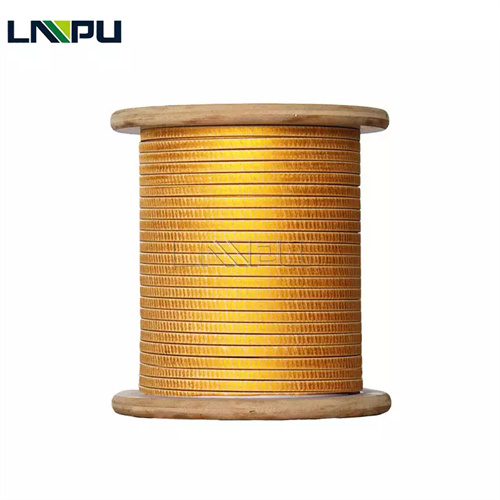
I. Definition of Varnished Fiberglass Covered Wire
Varnished Fiberglass Covered Wire refers to a composite insulated magnet wire comprising: a copper or aluminum conductor; an outer reinforcement layer formed by helical wrapping of fiberglass yarn; and a binding/auxiliary insulation layer achieved via impregnation and thermal curing of insulating varnish. Its standardized English designation is Varnished Fiberglass Covered Magnet Wire, falling under the Glass Fiber Covered + Varnish Treated category (e.g., MW 41-C, MW 44-C, MW 47-C, MW 50-C) specified in NEMA MW 1000-2018 Part 2.
In electrical insulation terminology, the term “Varnished” specifically denotes a process wherein the pre-wrapped fiberglass yarn is immersed in insulating varnish—or varnish is applied onto the fiberglass layer—and subsequently heat-cured. This ensures full penetration of the varnish into interstitial voids within the fiberglass matrix, forming a continuous enamel coating. The varnish serves three critical functions in VFG wire: 1) Acts as a binder between individual fiberglass filaments, consolidating the otherwise loose fiberglass layer into a monolithic structure; 2) Fills air gaps within the fiberglass layer, thereby enhancing dielectric strength; 3) Imparts moisture resistance, chemical corrosion resistance, and surface smoothness to the fiberglass layer.
By conductor geometry, VFG wire is classified into Round VFG Wire and Rectangular VFG Wire. By number of fiberglass layers: single-layer or double-layer. By thermal class of the varnish: Class F (155°C), Class H (180°C), or Class C (220°C). By varnish chemistry: oleo-resin varnish, polyester varnish, polyester-silicone hybrid varnish, pure silicone varnish, or polyimide varnish.
II. Structure of Varnished Fiberglass Covered Wire
The typical cross-sectional structure of VFG wire comprises four concentric layers—from innermost to outermost:
Layer 1: Conductor
Conductor material is electrolytic tough pitch (ETP) copper round wire (TR series, diameter Φ 0.50–Φ 6.00 mm) or copper flat wire (TBR series, thickness a = 0.80–5.60 mm, width b = 3.00–16.00 mm), compliant with GB/T 5584.2 and ASTM B49. Aluminum conductors (LR/LBR series, per GB/T 5584.3) are employed in weight-sensitive applications. Minimum purity requirements: ≥ 99.9% Cu or ≥ 99.5% Al; maximum resistivity: ≤ 0.01724 Ω·mm²/m at 20°C (copper).
Layer 2: Fiberglass Covering
Alkali-free E-glass fiber yarn (filament diameter 6–9 μm; yarn linear density 6.6–22 tex) is helically wound around the conductor. For single-layer wrapping, fiberglass coverage density is 80–120 filaments/cm, with overlap ratio of 50%–80%. Double-layer wrapping yields greater overall insulation thickness, higher dielectric strength, and enhanced mechanical robustness. Precise control of winding angle, tension, and pitch is essential.
Layer 3: Varnish Layer
Insulating varnish fully penetrates the fiberglass layer via immersion, then forms a continuous enamel coating upon thermal curing. Enamel coating thickness varies with varnish type and number of impregnation cycles, typically ranging from 0.01–0.05 mm. This layer eliminates inter-filament air voids, rendering the composite insulation dense and structurally integrated.
Layer 4: Surface Layer
The cured enamel coating forms a smooth, continuous, and impermeable outer surface over the fiberglass layer—providing moisture resistance, chemical corrosion resistance, dielectric strength, and mechanical protection.
Total insulation thickness (single-side):
- Single-layer fiberglass + varnish: 0.10–0.25 mm (for both round and rectangular wire);
- Double-layer fiberglass + varnish: 0.20–0.40 mm.
III. Comparison: Varnished Fiberglass Covered Wire vs. Conventional Fiberglass-Covered Wire vs. Enameled Wire
Distinction from Conventional Fiberglass-Covered Wire (Non-Varnished): Conventional fiberglass-covered wire undergoes only thermal setting or light surface coating post-wrapping. Significant air voids remain within the fiberglass layer, resulting in comparatively low dielectric strength and poor moisture resistance. In contrast, VFG wire employs vacuum or atmospheric-pressure varnish impregnation to fully saturate the fiberglass matrix—yielding a dense, homogeneous composite insulation. This improves dielectric strength by 30%–80% and significantly enhances moisture resistance and chemical corrosion resistance.
Distinction from Enameled Wire: Enameled wire (e.g., UEW – polyurethane, PEW – polyester, EIW – polyester-imide, AIW – polyamide-imide) features a direct insulating varnish coating applied onto the conductor. Its enamel coating is thin (0.02–0.10 mm), offers thermal classes ranging from 130°C to 240°C, and exhibits limited mechanical strength. In contrast, VFG (varnish-impregnated glass-fiber) magnet wire incorporates a reinforced glass-fiber layer, delivering significantly superior mechanical properties—including abrasion resistance, cut-through resistance, and impact resistance—compared to enameled wire. Moreover, VFG magnet wire covers thermal classes F, H, and C, making it especially suitable for high-temperature (H/C-class) and high-mechanical-stress application scenarios.
Distinction from Paper-Covered Wire: Paper-covered wire (NEMA MW 31-C, MW 33-C) employs cellulose paper tape wrapping and requires impregnation with transformer oil for service; its maximum operating temperature is approximately 105°C (Class A). VFG magnet wire utilizes high-temperature-resistant glass fiber combined with an insulating varnish coating, enabling continuous operation at 155–220°C without oil impregnation—ideal for dry-type or open-winding applications.
Distinction from Mica Tape-Wrapped Wire: Mica tape (e.g., Micabond / Mica Tape) is predominantly used for insulation of high-voltage motor coils (≥ 6 kV). VFG magnet wire is primarily intended for low- to medium-voltage windings (≤ 35 kV). The two systems may be combined—for instance, in VFG + mica composite-wrapped wire, conforming to NEMA MW 65-C and IEC 60317-46.
IV. Manufacturing Process of Varnish-Impregnated Glass-Fiber (VFG) Magnet Wire
The typical manufacturing process flow for VFG magnet wire is as follows:
Step 1: Conductor Pre-treatment Round or flat copper conductor or aluminum conductor undergoes surface cleaning and roughening prior to glass-fiber wrapping—via mechanical scraping or chemical micro-etching—to remove oxide scale, oil contamination, and burrs. For copper conductors, surface “matting” or passivation treatments may be applied to enhance enamel coating adhesion.
Step 2: Glass-Fiber Wrapping E-Glass (alkali-free) glass-fiber yarn is helically wrapped around the conductor using a dedicated wrapping machine. Critical process parameters include:
- Wrapping speed: 200–500 rpm
- Wrapping tension: 1.0–3.0 N
- Glass-fiber overlap rate: 50%–80%
- Wrapping angle: adjusted according to conductor diameter
After single-layer wrapping, the wire proceeds either to a “pre-curing” stage or directly to impregnation. For double-layer wrapping, an intermediate cure step may be introduced between layers.
Step 3: Varnish Impregnation (Core Process) Varnish impregnation distinguishes VFG magnet wire from standard glass-fiber-wrapped wire. Three primary impregnation methods are employed:
(1) Atmospheric-Pressure Impregnation: The glass-fiber-wrapped conductor is immersed in a varnish bath, allowing capillary action to draw varnish into the fiber interstices. Suitable for thin insulation systems and low-viscosity varnishes.
(2) Vacuum-Pressure Impregnation (VPI): Air is first evacuated from the glass-fiber layer under vacuum (residual pressure ≤ 100 Pa), followed by varnish injection and pressurization (0.2–0.6 MPa) to ensure complete penetration. Used for thick insulation and high-reliability applications.
(3) Continuous Drip Coating / Roll Coating: Varnish is continuously applied via drip nozzles or roll-coating units synchronized with the glass-fiber wrapping process—optimized for automated, high-volume production.
Varnish viscosity (at 25°C) is typically controlled within 250–450 mPa·s; immersion time is 20–60 s for continuous production or 30–60 min for batch-type VPI.
Step 4: Curing Following impregnation, the wire enters a curing oven—either a continuous tunnel furnace or batch-type oven—with temperature and dwell time selected per thermal class:
- Class F varnish: 130–150°C × 4–6 h
- Class H varnish: 180–200°C × 4–8 h
- Class C varnish: 220–240°C × 6–10 h
Temperature uniformity during curing must be maintained within ±5°C to prevent enamel coating defects such as blistering, cracking, or localized under-cure.
Step 5: In-Line Quality Inspection During VFG magnet wire manufacturing, in-line or sampling-based quality inspections shall cover:
- Glass-fiber coverage density
- Insulation thickness
- Conductor resistance
- Insulation resistance
- Dielectric breakdown voltage
- Enamel coating adhesion (cross-hatch test ≥ 4B rating)
- Solvent resistance
- Flexibility (no cracking after 180° bend)
- Enamel coating appearance (free of bubbles, foreign particles, or missed coating areas)
V. International Standards and Specifications for Varnish-Impregnated Glass-Fiber (VFG) Magnet Wire
The internationally recognized standard for VFG magnet wire is ANSI/NEMA MW 1000-2018 Part 2, with key specifications listed below (ordered by thermal class):
| NEMA Specification | Conductor Shape | Glass Fiber Layers | Impregnating Varnish | Thermal Class | Equivalent GB/T 7672 |
|---|---|---|---|---|---|
| MW 41-C | Round wire | Single-layer | Polyester / Oil-based | F (155°C) | GB/T 7672.4 |
| MW 42-C | Flat wire | Single-layer | Polyester / Oil-based | F (155°C) | GB/T 7672.4 |
| MW 44-C | Round wire | Single-layer | Polyester + Silicone | H (180°C) | GB/T 7672.5 |
| MW 45-C | Round wire | Double-layer polyester glass fiber | Polyester | F (155°C) | Extended GB/T 7672.4 |
| MW 46-C | Flat wire | Double-layer polyester glass fiber | Polyester | F (155°C) | Extended GB/T 7672.4 |
| MW 47-C | Round wire | Double-layer | Polyester + Silicone | H (180°C) | GB/T 7672.5 |
| MW 48-C | Flat wire | Double-layer | Polyester + Silicone | H (180°C) | GB/T 7672.5 |
| MW 50-C | Round wire | Single-layer | High-temperature organic varnish | H (180°C) | GB/T 7672.5 |
| MW 52-C | Flat wire | Single-layer | High-temperature organic varnish | H (180°C) | GB/T 7672.5 |
| MW 51-C | Round wire | Double-layer | High-temperature organic varnish | H (180°C) | GB/T 7672.5 |
| MW 53-C | Flat wire | Double-layer | High-temperature organic varnish | H (180°C) | GB/T 7672.5 |
In addition, IEC 60317 (series standard for winding wires), GB/T 7672 (enameled glass fiber wound wires for electrical insulation), and IEEE 57 (transformer winding wires) also specify corresponding requirements for VFG (varnish-impregnated glass fiber) wound wires.
VI. VFG Varnish-Impregnated Glass Fiber Wound Wire vs. Conventional Glass Fiber Wound Wire: Key Performance Comparison
Compared to conventional glass fiber wound wire (unimpregnated or lightly coated), VFG varnish-impregnated glass fiber wound wire demonstrates significant performance improvements in critical parameters:
| Performance Parameter | Conventional Glass Fiber Wound Wire | VFG Varnish-Impregnated Glass Fiber Wound Wire | Improvement Ratio |
|---|---|---|---|
| Dielectric Strength (between turns) | 0.8–1.5 kV | 1.5–3.5 kV | +80%–130% |
| Insulation Resistance (normal condition) | 50–100 MΩ·km | 200–500 MΩ·km | +200%–400% |
| Moisture Resistance (dielectric loss after 96 h at 40°C/95% RH) | Significantly increased | Stable | Significant improvement |
| Mechanical Strength (abrasion resistance, cut resistance) | Medium | Excellent | One grade improvement |
| Enamel Coating Adhesion | Prone to delamination | ≥4B rating | Significant improvement |
| Long-term Operating Temperature Rise | Slightly higher | Lower (superior thermal conductivity) | Reduction of 5–10 K |
Typical Application Scenarios: Conventional glass fiber wound wire is suitable for general-purpose F/H-class motor windings; VFG varnish-impregnated glass fiber wound wire is applied in high-reliability, long-life, high-moisture-resistance applications such as H/C-class high-voltage motors, traction motors, railway systems, wind power generation, and nuclear power systems.
VII. Typical Applications of Varnish-Impregnated Glass Fiber Wound Wire
1. Traction Motors (Rail Transit) Traction motors for rail transit require thermal class H (180°C) or higher, vibration resistance, and service life exceeding 30 years. VFG varnish-impregnated glass fiber wound wire (e.g., MW 47-C and MW 48-C double-layer H-class variants) is widely used in rotor and stator windings of traction motors, complying with IEC 60349 and IEC 60034.
2. H/C-Class Dry-Type Transformers Dry-type transformers rely on solid insulation (oil-free design). H-class (180°C) dry-type transformers employ VFG varnish-impregnated glass fiber wound flat wire (e.g., MW 43-C, MW 48-C) for both HV and LV windings. C-class (220°C) dry-type transformers further integrate mica composite insulation with VFG wire, meeting GB 1094.11 and IEC 60076-11 requirements.
3. Large Motors and Generators Large vertical hydro-generators and turbo-generators (100–1000 MW) deployed in thermal power plants, hydropower stations, and pumped-storage facilities utilize VFG varnish-impregnated glass fiber wound flat wire (e.g., MW 48-C, MW 53-C) for stator windings, conforming to IEC 60034, IEEE C50.10, and C50.13 standards.
4. Wind Power and Offshore Wind Power Wind turbines (onshore: 1.5–5 MW; offshore: 6–15 MW) operate under harsh conditions including high humidity, salt fog, mechanical vibration, and wide temperature fluctuations. The superior moisture resistance, anti-salt-fog corrosion capability, and thermal fatigue resistance of VFG varnish-impregnated glass fiber wound wire make it the preferred material for stator windings in wind turbine generators, compliant with IEC 61400-25 and GL classification society specifications.
5. Nuclear Power Main Pump Motors
Nuclear Power Plant Reactor Coolant Pump (Main Coolant Pump) Motor Requirements: 60-year service life, seismic resistance, and high reliability. VFG enameled wire with glass fiber wrapping + mica tape composite insulation system (VFG + Mica Tape) is applied to stator windings of nuclear main pumps, compliant with IEEE 334 and RCC-M standards.
6. Household Appliances (Thermal Class H) Thermal Class H-rated household appliances—including ovens, water heaters, space heaters, and dryers—employ VFG enameled wire with glass fiber wrapping (round wire, MW 44-C, MW 50-C) as heating element windings, certified under UL 1446 insulation system requirements.
7. Chemical-Resistant Motors Motors used in corrosive environments—such as chemical plants, mining operations, and offshore platforms—require insulation layers resistant to acids, alkalis, oils, and general chemical corrosion. VFG enameled wire with glass fiber wrapping—particularly those utilizing silicone-based varnish systems—exhibits excellent chemical corrosion resistance, conforming to API 541 and NEMA MG 1 standards.
VIII. VFG Enameled Wire Selection Guidelines
Motor and transformer manufacturers are advised to follow these steps when selecting VFG enameled wire with glass fiber wrapping:
Step 1: Determine Thermal Class Select thermal class F (155 °C), H (180 °C), or C (220 °C) based on operating temperature. Allow a safety margin: continuous operating temperature shall be at least 20 °C lower than the enamel coating’s thermal index.
Step 2: Determine Conductor Shape and Specifications Round wire (Φ 0.50–Φ 6.00 mm) is suitable for automated winding machines (small motors, household appliances); flat wire (a = 0.80–5.60 mm, b = 3.00–16.00 mm) is used for form-wound coils (large motors, transformers), achieving high slot fill factor.
Step 3: Determine Number of Glass Fiber Layers Single-layer glass fiber (lightweight, thin insulation) is appropriate for standard Thermal Class F/H applications; double-layer glass fiber (thick insulation, high mechanical strength) is recommended for Thermal Class H/C, high-vibration, or high-voltage applications.
Step 4: Select Varnish System Oil-based varnish (cost-effective, Thermal Class B/F) → polyester varnish (standard Thermal Class F, 155 °C) → polyester + silicone varnish (enhanced Thermal Class H, 180 °C) → pure silicone varnish (maximum Thermal Class H moisture resistance, 180 °C) → polyimide varnish (Thermal Class C, 220 °C). For high-humidity or chemically aggressive environments, silicone or polyimide varnishes are preferred.
Step 5: Verify Vacuum Pressure Impregnation (VPI) Compatibility Confirm whether the glass fiber-wrapped wire supplier provides VPI-compatible varnish systems and validated curing parameters. VPI processing significantly enhances overall insulation strength and moisture resistance of VFG enameled wire.
Step 6: International Certifications and Quality Documentation Verify that the supplier holds ISO 9001, ISO 14001, and ISO 45001 management system certifications; UL 1446 (motor insulation systems) and UL 1004 certifications; RoHS compliance and REACH compliance documentation; and provides Mill Test Certificate (MTC) and test reports per batch.
IX. Technical Specifications Overview (LP Industry)
Zhengzhou LP Industry Co., Ltd. specializes in R&D and manufacturing of magnet wire and metal foil materials. Its products are exported to over 50 countries and regions, backed by 30 years of industry experience.
For VFG enameled wire with glass fiber wrapping, LP Industry offers the following technical specifications:
- Conductor Materials**: TU1 oxygen-free copper / T2 electrolytic tough pitch (ETP) copper / 1060 pure aluminum (compliant with GB/T 3953 and ASTM B49);
- Conductor Shapes & Dimensions**: Round wire Φ 0.50–6.00 mm; flat wire thickness 0.80–5.60 mm × width 3.00–16.00 mm (compliant with GB/T 5584 and IEC 60317-0-2);
- Glass Fiber Type**: E-Glass (alkali-free), 6.6–22 tex;
- Glass Fiber Layers**: Single-layer / double-layer;
- Varnish Systems**: Oil-based varnish (Thermal Class B/F), polyester varnish (Thermal Class F, 155 °C), polyester + silicone varnish (Thermal Class H, 180 °C), pure silicone varnish (Thermal Class H, 180 °C), high-temperature organic varnish (Thermal Class H, 180 °C), polyimide varnish (Thermal Class C, 220 °C);
- Thermal Classes**: F (155 °C), H (180 °C), C (220 °C);
- Impregnation Processes**: Atmospheric impregnation / vacuum pressure impregnation (VPI);
- Product Coverage**: Full range of NEMA MW 41-C through MW 53-C models;
- Standards Compliance**: ANSI/NEMA MW 1000-2018, IEC 60317, GB/T 7672, IEEE C57;
- Certifications**: ISO 9001, ISO 14001, ISO 45001 (SGS-audited); full UL certification, RoHS compliance, REACH compliance.
LP Industry supports small-batch customization and joint R&D for new product models—including VPI process integration—with an R&D response cycle of 7–15 days.
Contact Information:
- Email: office@cnlpzz.com
- WhatsApp: +86-19337889070
X. Conclusion
VFG enameled wire with glass fiber wrapping is a composite-insulated conductor combining glass fiber wrapping and insulating varnish impregnation, delivering both high mechanical strength from the glass fiber and dense, uniform insulation performance from the enamel coating. VFG enameled wire demonstrates outstanding performance under demanding conditions—including high temperature (Thermal Classes F/H/C), vibration, high-humidity environment, and chemical corrosion—and is the preferred winding material for high-end equipment such as traction motors, dry-type transformers, large generators, wind power generators, and nuclear power plant equipment.
Understanding the structure, operating principle, manufacturing process, and material selection criteria of VFG (Vacuum Pressure Impregnation) is the technical foundation for ensuring long-term reliable operation of motors and transformers. Leveraging 30 years of experience in magnet wire and metal foil manufacturing, LP Industry provides customers with end-to-end technical support—from material selection and sample testing to VPI process compatibility and mass production supply. Technical consultation and sample requests are welcome.