


Glass-fiber covered magnet wire (also referred to as fiberglass-covered magnet wire or glass-fiber insulated magnet wire) is a composite insulated conductor consisting of a copper or aluminum round wire or flat wire conductor, helically wrapped with alkali-free E-glass fiber yarn, and subsequently impregnated and cured with silicone varnish, polyester-imide varnish, or oleo-resin varnish. This type of magnet wire offers high temperature resistance (thermal classes ranging from 155 °C — Class F — up to 240 °C — Class C), radiation resistance, chemical corrosion resistance, excellent mechanical strength, and moisture resistance. It is widely used in traction motors, dry-type transformers, household appliances (ovens, water heaters), Class H/C motors, nuclear power equipment, and wind power generators.
This document provides a systematic overview of the main types of glass-fiber covered magnet wire available on the market, classified and detailed in accordance with internationally recognized standards including ANSI/NEMA MW 1000-2018, IEC 60317, and GB/T 7672.4/.5. It outlines structural configurations, specifications, technical specifications, and typical application scenarios for each type — serving as a technical reference for R&D engineers and procurement professionals in motor, transformer, and appliance manufacturing industries.
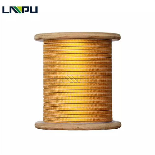
I. Market Classification Overview of Glass-Fiber Covered Magnet Wire
Based on conductor shape, number of glass-fiber layers, impregnating varnish type, and thermal class, commercially available glass-fiber covered magnet wire is categorized as follows. Full classification corresponds to NEMA MW 1000-2018 Part 2 (Specifications MW 41-C through MW 53-C).
By conductor shape:
- Round glass-fiber covered wire**: Diameter range Φ 0.50–Φ 6.00 mm; corresponding to NEMA MW 41-C, MW 44-C, MW 45-C, MW 47-C, MW 50-C, MW 51-C
- Rectangular glass-fiber covered wire**: Thickness 0.80–5.60 mm, width 3.00–16.00 mm; corresponding to NEMA MW 42-C, MW 43-C, MW 46-C, MW 48-C, MW 52-C, MW 53-C
By number of glass-fiber wrapping layers:
- Single-layer glass-fiber covered wire**: One layer of E-glass fiber yarn helically wrapped
- Double-layer glass-fiber covered wire**: Two superimposed layers of E-glass fiber yarn; provides increased insulation thickness and enhanced mechanical strength
By impregnating varnish (binder) type:
- Oleo-resin varnish treated glass-fiber covered wire**: Conventional Class B/F impregnating varnish
- Polyester varnish treated glass-fiber covered wire**: Class F (155 °C)
- Polyester-silicone varnish treated glass-fiber covered wire**: Class H (180 °C)
- Silicone varnish treated glass-fiber covered wire**: Class H (180 °C)
- Polyester-imide/polyamide-imide varnish treated glass-fiber covered wire**: Class H/C (200–220 °C)
By thermal class:
- Class A (105 °C — rarely used with glass-fiber insulation)
- Class B (130 °C — uncommon for glass-fiber systems)
- Class F (155 °C)
- Class H (180 °C)
- Class C (220 °C — achieved via polyimide/mica composites)
- Ultra-Class C (240 °C — achieved via aromatic polyamide/mica composites)
II. Detailed Description of Commonly Available Glass-Fiber Covered Magnet Wire Types
2.1 Single-Layer Glass-Fiber Covered Round Wire (Class F, 155 °C)
Structure: Copper (or aluminum) round wire conductor, helically wrapped with one layer of alkali-free E-glass fiber yarn (single filament diameter 6–9 μm), impregnated with polyester varnish or oleo-resin varnish, and thermally cured.
Applicable Standard: NEMA MW 41-C (Glass Fiber Covered, Polyester Glass Fiber Covered — 155 °C series).
Key Technical Specifications:
- Conductor diameter: Φ 0.50–Φ 6.00 mm
- Glass-fiber coverage density: 80–120 filaments/cm (dependent on wire diameter)
- Insulation thickness (single-layer glass-fiber): 0.10–0.20 mm (increased by ~30% after impregnation and curing)
- Thermal class: 155 °C (Class F)
- Dielectric strength: ≥ 1.5 kV (measured between turns after coil impregnation)
- Temperature index: ≥ 155 °C (verified by 20,000-hour life test per IEEE 100)
Typical Application Scenarios:
- Motor windings for household appliances (air conditioner compressors, washing machines, refrigerators, freezers, range hoods)
- Low- to medium-voltage small motors
- Small transformer coils
- General-purpose Class F motors
2.2 Single-Layer Glass-Fiber Covered Round Wire (Class H, 180 °C)
Structure: Copper round wire conductor, single-layer E-glass fiber helical wrap, impregnated with polyester-silicone hybrid varnish or pure silicone varnish.
Applicable Standard: NEMA MW 44-C (Glass Fiber Covered, Silicone Treated).
Key Performance Indicators: Conductor diameter Φ 0.50–Φ 6.00 mm; glass fiber coverage density 80–120 filaments/cm; insulation thickness 0.10–0.20 mm; thermal class 180℃ (Class H); temperature index ≥ 180℃ (20,000 h); excellent flexibility (suitable for shaped winding and bending); superior moisture resistance.
Typical Applications: Class H motor windings, traction motors, hoisting & metallurgical motors, corrosion-resistant motors for chemical industry, outdoor weather-resistant motors.
2.3 Double-Layer Glass Fiber Covered Round Wire (Class H, 180℃)
Construction: Bare copper round wire covered with two independent layers of glass fiber yarn (wound in same or crossed direction), impregnated with polyester + silicone varnish or pure silicone varnish.
Applicable Standards: NEMA MW 47-C (Polyester Glass Fiber Covered, Silicone Treated).
Key Performance Indicators: Conductor diameter Φ 0.80–Φ 6.00 mm; total double-layer glass fiber thickness 0.20–0.35 mm; thermal class 180℃ (Class H); dielectric strength ≥ 3.0 kV (between turns); significantly enhanced mechanical strength (abrasion resistance, cut resistance) compared to single-layer construction; temperature index ≥ 180℃ (20,000 h).
Typical Applications: Class H high-voltage motors, large traction motors, railway traction transformers, mining motors, wind turbine generators, nuclear power equipment.
2.4 Single-Layer Glass Fiber Covered Flat Wire (Class F, 155℃)
Construction: TBR flat copper wire (thickness a = 0.80–5.60 mm, width b = 3.00–16.00 mm, compliant with GB/T 5584.2), covered with a single layer of glass fiber, impregnated with polyester varnish or oil-based varnish.
Applicable Standards: NEMA MW 42-C (Rectangular Glass Fiber Covered, 155℃ series), GB/T 7672.4.
Key Performance Indicators: Conductor dimensions a = 0.80–5.60 mm, b = 3.00–16.00 mm; glass fiber coverage density 80–120 filaments/cm; insulation thickness 0.10–0.25 mm (per side); thermal class 155℃ (Class F); temperature index ≥ 155℃; high slot fill factor (optimized for Class F motor formed windings).
Typical Applications: Class F dry-type transformers, Class F motor formed windings, rail traction motors, wind turbine generators, high-power reactors.
2.5 Single-Layer Glass Fiber Covered Flat Wire (Class H, 180℃)
Construction: TBR flat copper wire covered with a single layer of glass fiber, impregnated with polyester + silicone hybrid varnish or pure silicone varnish.
Applicable Standards: NEMA MW 43-C (Rectangular Glass Fiber Covered, Silicone Treated), GB/T 7672.5.
Key Performance Indicators: Conductor dimensions a = 0.80–5.60 mm, b = 3.00–16.00 mm; glass fiber coverage density 80–120 filaments/cm; insulation thickness 0.10–0.25 mm; thermal class 180℃ (Class H); temperature index ≥ 180℃ (20,000 h); chemical corrosion resistance (acid-, alkali-, and oil-resistant); radiation resistance.
Typical Applications: Class H dry-type transformers, Class H high-voltage motors, traction motors, flameproof mining motors, corrosion-resistant motors for chemical industry.
2.6 Double-Layer Glass Fiber Covered Flat Wire (Class H, 180℃)
Construction: TBR flat copper wire covered with two layers of glass fiber yarn, impregnated with polyester + silicone varnish or pure silicone varnish.
Applicable Standards: NEMA MW 48-C (Rectangular Polyester Glass Fiber Covered, Silicone Treated).
Key Performance Indicators: Conductor dimensions a = 0.80–5.60 mm, b = 3.00–16.00 mm; total double-layer glass fiber thickness 0.20–0.40 mm; thermal class 180℃ (Class H); dielectric strength ≥ 3.5 kV (between turns); outstanding mechanical strength (cut resistance, vibration resistance); temperature index ≥ 180℃.
Typical Applications: Class H high-power traction motors, Class H ultra-high-voltage transformers, nuclear power main pump motors, offshore wind turbine generators, military-grade equipment.
2.7 High-Temperature Organic Varnish Treated Glass Fiber Covered Round Wire (Class H, 180℃)
Construction: Bare copper round wire covered with a single layer of glass fiber, impregnated with high-temperature organic varnish.
Applicable Standards: NEMA MW 50-C (Glass Fiber Covered, High-Temperature Organic Varnish Treated).
Key Performance Indicators: Conductor diameter Φ 0.50–Φ 6.00 mm; thermal class 180℃ (Class H); temperature index ≥ 180℃; excellent flexibility (compatible with automatic winding machines); high moisture resistance (low dielectric loss under high-humidity conditions).
Typical Applications: Class H small motors, power tools, gardening tools, Class H household appliances.
2.8 High-Temperature Organic Varnish Treated Glass Fiber Covered Flat Wire (Class H, 180℃)
Construction: TBR flat copper wire covered with a single layer of glass fiber, impregnated with high-temperature organic varnish.
Corresponding Standard: NEMA MW 52-C (Rectangular Glass Fiber Covered, High-Temperature Organic Varnish Treated).
Key Performance Specifications:
- Conductor dimensions: a = 0.80–5.60 mm, b = 3.00–16.00 mm;
- Thermal class: 180 °C (Class H);
- Temperature index ≥ 180 °C;
- High moisture resistance;
- Excellent mechanical strength.
Typical Applications: Class H dry-type transformers, Class H high-power motors, Class H reactors.
2.9 Double-Layer Polyester-Glass Fiber Covered Round Wire (Class F, 155 °C)
Construction: Copper round wire wrapped with double-layer polyester fiber + glass fiber composite tape, impregnated with polyester varnish.
Corresponding Standard: NEMA MW 45-C (Double Polyester Glass Fiber Covered, 155 °C).
Key Performance Specifications:
- Conductor diameter: Φ 0.50–Φ 6.00 mm;
- Total thickness of double-layer composite fiber: 0.15–0.30 mm;
- Thermal class: 155 °C (Class F);
- Exceptional flexibility (suitable for automated winding);
- Stable electrical performance.
Typical Applications: Class F high-efficiency motors, transformers, Class F household appliance motors.
2.10 Double-Layer Polyester-Glass Fiber Covered Flat Wire (Class F, 155 °C)
Construction: TBR flat copper wire wrapped with double-layer polyester fiber + glass fiber composite tape, impregnated with polyester varnish.
Corresponding Standard: NEMA MW 46-C (Double Polyester Glass Fiber Covered, 155 °C), extended per GB/T 7672.4.
Key Performance Specifications:
- Conductor dimensions: a = 0.80–5.60 mm, b = 3.00–16.00 mm;
- Total thickness of double-layer composite fiber: 0.20–0.40 mm;
- Thermal class: 155 °C (Class F);
- Temperature index ≥ 155 °C;
- High flexibility and high slot fill factor.
Typical Applications: Class F dry-type transformers, Class F high-efficiency motors, drive motors for new-energy vehicles.
2.11 Glass Fiber + Mica Composite Covered Wire (Class C, 220 °C)
Construction: Copper wire wrapped with glass fiber + mica tape (mica paper reinforced with glass fiber), impregnated with high-temperature silicone organic varnish or polyimide varnish.
Corresponding Standard: Referenced to IEC 60317-46 and GB/T 7672.6 (mica/glass fiber composite insulation).
Key Performance Specifications:
- Conductor specifications: Φ 0.50–Φ 6.00 mm (round wire) or flat wire a = 0.80–5.60 mm;
- Total composite insulation thickness: 0.30–0.80 mm;
- Thermal class: 220 °C (Class C);
- Temperature index ≥ 220 °C;
- Corona resistant;
- Flame-retardant (UL 94 V-0);
- High dielectric strength (≥ 10 kV).
Typical Applications: Class C ultra-high-temperature motors, nuclear power primary pump motors, aerospace motors, fire-resistant cables, direct-drive wind turbine generators.
III. Comparative Table of Market Glass Fiber Covered Wire Types
The table below summarizes key parameters of 11 mainstream glass fiber covered wire types available in the market, facilitating rapid comparison and material selection (based on ANSI/NEMA MW 1000-2018, GB/T 7672, and IEC 60317 standards):
| Type No. | Conductor | Glass Fiber Layers | Impregnating Varnish | Thermal Class | NEMA Specification | Key Features | Typical Applications |
|---|---|---|---|---|---|---|---|
| ① Single-Glass-Fiber-Wrapped Round Wire | Round | Single-layer | Polyester / Oil-based | F (155°C) | MW 41-C | General-purpose, cost-effective | Household appliance motors, small motors |
| ② Single-Glass-Fiber-Wrapped Round Wire | Round | Single-layer | Polyester + Silicone | H (180°C) | MW 44-C | High temperature resistance, moisture resistance | Class H motors, outdoor motors |
| ③ Double-Glass-Fiber-Wrapped Round Wire | Round | Double-layer | Polyester + Silicone | H (180°C) | MW 47-C | High insulation strength, high mechanical strength | Traction motor, railway applications, nuclear power equipment |
| ④ Single-Glass-Fiber-Wrapped Flat Wire | Flat | Single-layer | Polyester / Oil-based | F (155°C) | MW 42-C | High slot fill factor | Class F dry-type transformer, Class F motors |
| ⑤ Single-Glass-Fiber-Wrapped Flat Wire | Flat | Single-layer | Polyester + Silicone | H (180°C) | MW 43-C | High temperature resistance, corrosion resistance | Class H dry-type transformer, Class H motors |
| ⑥ Double-Glass-Fiber-Wrapped Flat Wire | Flat | Double-layer | Polyester + Silicone | H (180°C) | MW 48-C | Ultra-high mechanical strength, high insulation performance | Traction systems, wind power generators, nuclear power equipment |
| ⑦ High-Temperature Organic Varnish Round Wire | Round | Single-layer | High-temperature organic varnish | H (180°C) | MW 50-C | High moisture resistance, high flexibility | Class H small motors, power tools |
| ⑧ High-Temperature Organic Varnish Flat Wire | Flat | Single-layer | High-temperature organic varnish | H (180°C) | MW 52-C | High moisture resistance, high mechanical strength | Class H dry-type transformer, Class H reactors |
| ⑨ Double-Layer Polyester-Glass-Fiber Round Wire | Round | Double-layer | Polyester | F (155°C) | MW 45-C | High flexibility, general-purpose | Class F high-efficiency motors, transformers |
| ⑩ Double-Layer Polyester-Glass-Fiber Flat Wire | Flat | Double-layer | Polyester | F (155°C) | MW 46-C | High flexibility, high slot fill factor | Class F dry-type transformer, new-energy vehicle motors |
| ⑪ Glass Fiber + Mica Composite Wire | Round/Flat | Multi-layer | Polyimide / Silicone | C (220°C) | IEC 60317-46 | Fire-resistant, corona resistant | Nuclear power equipment, aerospace, fire-rated cables |
IV. Key Manufacturing Process Points for Glass-Fiber-Wrapped Magnet Wire
4.1 Glass Fiber Wrapping Process
The core process of glass-fiber-wrapped magnet wire involves helical wrapping of E-glass fiber yarn (alkali-free, yarn count 6.6–22 tex) around the conductor. Wrapping tension is controlled at 1.0–3.0 N (determined by wire diameter and glass fiber specification); wrapping speed ranges from 200–500 rpm; fiber overlap rate is maintained at 50%–80%; thickness increment per single glass fiber layer is 0.10–0.20 mm for round wire and 0.10–0.25 mm per side for flat wire.
4.2 Impregnation and Curing
After wrapping, the glass-fiber-wrapped magnet wire enters the impregnation oven: varnish viscosity at 25°C is 250–450 mPa·s; impregnation time is 20–45 s; curing temperature and duration are as follows:
- Class F: 130–150°C × 4–6 h
- Class H: 180–200°C × 4–8 h
- Class C: 220–240°C × 6–10 h
Temperature uniformity must be strictly controlled within ±5°C during curing to prevent enamel coating blistering or cracking.
4.3 Critical Quality Control Parameters
Key quality indicators for glass-fiber-wrapped magnet wire include:
- Glass fiber coverage density (≥ 80 filaments/cm)
- Insulation thickness uniformity (±0.02 mm)
- Conductor resistance
- Insulation resistance (≥ 100 MΩ·km)
- Dielectric breakdown voltage
- Flexibility (bending test: bending radius R = 1× wire diameter, no cracking after 180° bend)
- Solvent resistance (no coating removal after wiping with xylene or acetone)
- Adhesion (cross-cut tape test ≥ 4B rating)
V. Typical Failure Modes and Mechanism Analysis
5.1 Enamel Coating Aging and Cracking
Failure Phenomenon: Enamel coating cracks and peels off after prolonged high-temperature operation. Failure Mechanism: Thermal oxidative degradation of silicone or polyester varnish under long-term exposure to temperatures exceeding 180°C leads to loss of coating elasticity. Improvement Measures: Use higher thermal class varnishes (e.g., polyimide varnish); maintain long-term operating temperature at least 20°C below the rated thermal index of the enamel coating; implement periodic maintenance and replacement.
5.2 Glass Fiber Abrasion and Penetration
Failure Phenomenon: Glass fiber insulation is scratched or punctured by sharp components during winding assembly, resulting in turn-to-turn short circuits. Failure Mechanism: Although glass fiber exhibits excellent high-temperature resistance, its abrasion resistance is limited; mechanical damage from sharp tools or metal burrs compromises insulation integrity. Improvement Measures: Deburr all winding assembly tools; select double-layer glass fiber or thick-enamel glass-fiber-wrapped magnet wire (e.g., MW 47-C, MW 48-C, MW 53-C); perform pre-assembly insulation testing (DC withstand voltage or partial discharge testing).
5.3 Reduced Moisture Resistance
Failure Phenomenon: Increased dielectric loss and decreased insulation resistance under high-humidity conditions. Failure Mechanism: Glass fiber yarn—particularly in incompletely impregnated areas—absorbs moisture, forming a conductive water film on the surface and degrading insulation performance. Improvement Measures: Use high-temperature organic varnish (MW 50-C, MW 52-C) or silicone varnish (MW 44-C, MW 47-C); ensure thorough impregnation and curing; apply vacuum pressure impregnation (VPI) post-treatment in high-humidity environments.
5.4 Solderability Issues
Failure Phenomenon: Difficulty in tinning and cold soldering (i.e., insufficient wetting) during soldering of fiberglass-bonded enameled wire leads. Failure Mechanism: Fiberglass braid and enamel coating impede solder wetting onto the copper conductor; carbonization residue of fiberglass under high-temperature soldering. Improvement Measures: Mechanically strip fiberglass braid + enamel coating from lead ends over a length of 30–50 mm prior to soldering; adopt laser stripping or chemical stripping; select fiberglass-bonded enameled wire with pre-plated nickel or tin coating.
VI. Technical Evaluation Criteria for Fiberglass-Bonded Enameled Wire Suppliers
Motor and transformer manufacturers are advised to conduct systematic supplier evaluation across the following dimensions:
- Product Standard Coverage:** Does the supplier cover the full range of NEMA MW 41-C to MW 53-C specifications?
- Conductor Materials:** Are TU1 oxygen-free copper, T2 electrolytic tough pitch (ETP) copper, and 1060 pure aluminum conductors available?
- Conductor Dimension Range:** Are round wire (Φ 0.50–Φ 6.00 mm) and flat wire (a = 0.80–5.60 mm × b = 3.00–16.00 mm) fully available?
- Impregnating Varnish Systems:** Are varnish systems supporting full thermal classes — F (155°C), H (180°C), and C (220°C) — offered?
- International Certifications:** ISO 9001, ISO 14001, and ISO 45001 management system certifications; UL certification (UL 1446 / UL 1004 for motor insulation systems); RoHS compliance and REACH compliance.
- R&D and Customization Capability:** Is small-batch customization supported (e.g., special wire diameters, specialty varnishes, customized overlap ratios)? What is the R&D response cycle?
- Supply Chain Stability:** Multi-source assurance for key raw materials — fiberglass yarn, silicone/polyester varnishes, and conductors (copper/aluminum); consistent delivery lead time.
VII. Technical Specifications Overview (LP Industry)
Zhengzhou LP Industry Co., Ltd. specializes in R&D and manufacturing of magnet wire and metal foil materials. Its products are exported to over 50 countries and regions, backed by 30 years of industry experience.
For fiberglass-bonded enameled wire, LP Industry offers the following technical specifications:
- Conductor Materials:** TU1 oxygen-free copper / T2 ETP copper / 1060 pure aluminum (compliant with GB/T 3953 and ASTM B49);
- Conductor Shapes & Dimensions:** Round wire: Φ 0.50–6.00 mm; Flat wire: thickness 0.80–5.60 mm × width 3.00–16.00 mm (compliant with GB/T 5584 and IEC 60317-0-2);
- Fiberglass Type:** Alkali-free E-Glass fiber (6.6–22 tex);
- Fiberglass Layers:** Single-layer or double-layer;
- Impregnating Varnish Systems:** Polyester varnish (Class F), polyester + silicone varnish (Class H), pure silicone varnish (Class H), polyimide varnish (Class C);
- Thermal Classes:** F (155°C), H (180°C), C (220°C);
- NEMA Coverage:** Full range from MW 41-C, MW 42-C, MW 43-C, MW 44-C, MW 45-C, MW 46-C, MW 47-C, MW 48-C, MW 50-C, MW 52-C, to MW 53-C;
- Specialty Products:** Fiberglass + mica composite bonded wire (220°C / 240°C), paper-wrapped + fiberglass composite insulated wire;
- Standards Compliance:** ANSI/NEMA MW 1000-2018, IEC 60317, GB/T 7672, IEEE 57;
- Certifications:** ISO 9001, ISO 14001, ISO 45001 (SGS-audited); UL certification, RoHS compliance, REACH compliance;
- Customization & Joint R&D:** Supports new product R&D and custom fiberglass-bonded enameled wire development; R&D response cycle: 7–15 days.
Contact Information:
- Email: office@cnlpzz.com
- WhatsApp: +86-19337889070
VIII. Conclusion
Fiberglass-bonded enameled wire is a core category of high-temperature insulation conductors rated for thermal classes F, H, and C. It is irreplaceable in application scenarios including traction motors, H/C-class dry-type transformers, nuclear power equipment, aerospace systems, and new-energy vehicles.
Commercially available products form a complete specification matrix across conductor shape (round/flat), fiberglass layer count (single/double), impregnating varnish system (polyester/silicone/polyimide), and thermal class — spanning the full NEMA MW 41-C to MW 53-C range.
During material selection, users must perform systematic material evaluation based on application-specific requirements: operating voltage level, power rating, continuous working temperature, mechanical stress, ambient media (e.g., humidity, chemicals), and design life — integrating optimization of conductor dimensions, fiberglass layer count, and impregnating varnish system.
With 30 years of expertise in magnet wire and metal foil manufacturing, LP Industry provides end-to-end technical support — from material selection and sample testing to mass production supply — for motor, transformer, and home appliance manufacturers. Technical consultation and sample request are welcome.