


Skin effect is the core phenomenon in high-frequency applications of winding wire. Understanding skin effect is critical for high-frequency transformers, inductors, wireless charging, motor drives, and other applications. This article systematically explains the physical principles, mathematical models, key parameters, impact on winding wire performance, and design solutions to reduce skin effect.
Basic Principles of Skin Effect
Definition of Skin Effect
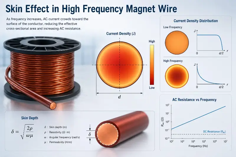
Skin effect refers to the phenomenon that when alternating current flows through a conductor, the current density is not uniformly distributed within the cross-section of the conductor, and the current is mainly concentrated on the surface layer (close to the surface) of the conductor. The higher the frequency, the more significant the skin effect.
Physical Mechanism
The physical basis of the skin effect is electromagnetic induction. When alternating current flows through a conductor, it generates a changing magnetic field inside the conductor. The changing magnetic field in turn induces eddy currents inside the conductor. According to Lenz’s law, the direction of the eddy current is opposite to the original current at the center of the conductor and the same on the surface. The superposition result is that the current in the central area of the conductor is weakened and the current on the surface is enhanced.
Frequency Characteristics
The strength of the skin effect is directly related to frequency. At DC or low frequencies (<1kHz), the current is basically uniformly distributed within the cross-section of the conductor, and the conductor utilization rate is high. At intermediate frequencies (1kHz-100kHz), the skin effect begins to appear. At high frequencies (>100kHz), the skin effect is significant, the current only flows in the surface thin layer, and the effective cross-sectional area of the conductor is greatly reduced.
Skin Depth
Definition of Skin Depth
Skin depth δ is the key parameter describing the skin effect, defined as the depth at which the current density decays to 1/e (about 36.8%) of the surface current density. The smaller the skin depth, the more severe the skin effect.
Skin Depth Formula
Skin depth formula: δ = √(2 / (ω × μ × σ)). Where: δ: skin depth (m), ω: angular frequency (rad/s), ω = 2πf, μ: conductor magnetic permeability (H/m), copper’s relative permeability is about 1, σ: conductor electrical conductivity (S/m), copper’s electrical conductivity is about 5.8×10^7 S/m, f: frequency (Hz).
Copper Conductor Skin Depth Reference Values
Skin Depth Reference
| Frequency | Skin Depth δ | Notes |
|---|---|---|
| 50 Hz | 9.3 mm | Power frequency, common copper wire diameter is smaller than this |
| 1 kHz | 2.1 mm | Audio applications |
| 10 kHz | 0.66 mm | Intermediate frequency applications |
| 100 kHz | 0.21 mm | Switching power supplies, induction heating |
| 1 MHz | 0.066 mm | Wireless charging, high-frequency transformers |
| 10 MHz | 0.021 mm | High-frequency communications |
| 100 MHz | 0.0066 mm | RF applications |
Impact of Skin Depth
When the wire diameter d >> 2δ (diameter much greater than twice the skin depth), the center area of the conductor has almost no current flow, resulting in serious material waste. When the wire diameter d ≤ 2δ, the current distribution within the cross-section of the conductor is relatively uniform, and the skin effect has less impact.
Impact of Skin Effect on Winding Wire
Increased AC Resistance
AC Resistance Reference
| Application Frequency | Skin Depth | Typical R_ac/R_dc |
|---|---|---|
| 50/60 Hz | 9.3 mm | 1.0-1.05 |
| 1 kHz | 2.1 mm | 1.1-1.5 |
| 10 kHz | 0.66 mm | 1.5-3.0 |
| 100 kHz | 0.21 mm | 3.0-10 |
| 1 MHz | 0.066 mm | 10-50 |
DC vs AC Resistance
The DC resistance R_dc is determined by the conductor material and cross-sectional area. The AC resistance R_ac increases significantly at high frequencies due to the skin effect. The R_ac / R_dc ratio increases with frequency.
Increased Copper Loss
The increase in AC resistance caused by the skin effect directly causes an increase in copper loss. Copper loss P = I² × R_ac. When R_ac increases significantly, copper loss may be several times the DC copper loss, seriously affecting winding efficiency.
Aggravated Temperature Rise
The skin effect causes the current to concentrate in the surface thin layer, and the surface current density is extremely high, resulting in local overheating. The temperature rise further increases the resistance, forming a vicious cycle.
Reduced Current Carrying Capacity
In high-frequency applications, due to the skin effect, the effective current carrying area is reduced, and the current carrying capacity per unit cross-sectional area is reduced. Larger cross-section conductors or specially designed winding wires (such as Litz wire) are needed to meet current carrying requirements.
Proximity Effect
Definition of Proximity Effect
Proximity effect refers to the phenomenon that the alternating current in a conductor is affected by the magnetic field of the adjacent conductor’s current, causing the current distribution to shift to one side. Proximity effect is closely related to skin effect and is particularly evident in windings.
Proximity Effect Mechanism
When multiple conductors are adjacent, the magnetic field generated by each conductor’s current affects the current distribution of adjacent conductors. In windings, the current tends to concentrate on the adjacent side surface, further reducing the effective cross-sectional area.
Differences Between Proximity Effect and Skin Effect
The skin effect is generated by the conductor’s own current, and the proximity effect is generated by the adjacent conductor’s current. In windings, the proximity effect is usually more severe than the skin effect. Inter-layer insulation and winding arrangement have a significant impact on the proximity effect.
Design Methods to Reduce Skin Effect
Litz Wire
Litz Wire Principle
Litz wire is made of multiple mutually insulated fine wires twisted together. The diameter of each fine wire is much smaller than the skin depth, so the current distribution in each fine wire is relatively uniform. By paralleling multiple fine wires, the total cross-sectional area is maintained while reducing the impact of skin effect and proximity effect.
Litz Wire Structure
Litz wire usually consists of multiple bundles, each bundle made of multiple (from 3 to thousands) enameled fine wires twisted together. Twisting methods include: single-strand twisting, multi-bundle twisting, concentric twisting, etc. Standard Litz wire strand numbers include: 5, 7, 10, 16, 27, 40, 105, etc.
Litz Wire Applications
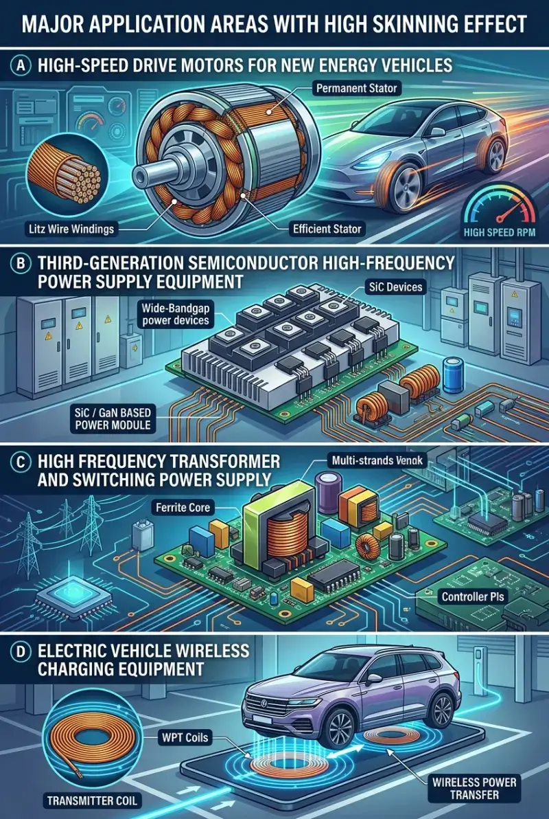
Litz wire is widely used in: wireless charging transmitter/receiver coils, high-frequency transformers (switching power supplies, UPS), induction heating equipment, medical high-frequency equipment, aviation high-frequency power supplies, electric vehicle wireless charging.
Litz Wire Specifications
Single wire diameter: 0.03mm – 0.20mm, total strands: 3 – 5000, working frequency: 10 kHz – 10 MHz, twisting pitch: 20mm – 100mm.
Flat Conductor (Copper Strip/Aluminum Foil)
Flat Conductor Principle
The thickness dimension of a flat conductor (rectangular wire / foil winding) can be made smaller than twice the skin depth. The current is uniformly distributed in the thickness direction, and the width dimension is large, increasing the total cross-sectional area.
Flat Conductor Applications
High-frequency high-power transformers, planar transformers, resonant inductors, high-power power supplies.
Flat Conductor Advantages
Controllable thickness, uniform current distribution, large heat dissipation area, neat winding arrangement, high fill factor.
Multi-Strand Twisted Round Wire
Multi-Strand Twisting Principle
Multi-strand twisted round wire is a compromise solution between Litz wire and single round wire. The number of strands is less than Litz wire, the process is simpler, and the cost is lower.
Multi-Strand Twisting Applications
Intermediate frequency transformers, intermediate frequency motor windings, induction heating, industrial heating.
Hollow Conductor
Hollow Conductor Principle
When the wall thickness of a hollow conductor is less than twice the skin depth, the skin effect has less impact. Since there is no material in the center, the weight is reduced and the cost is lowered.
Hollow Conductor Applications
High-power high-frequency equipment, special transformers, RF applications.
Surface Treatment
Silver-Plated Copper Wire
Silver plating on the surface of copper wire, using silver’s higher electrical conductivity to reduce high-frequency resistance. Silver’s skin depth is slightly larger than copper’s, but the difference is small. Silver plating mainly improves surface contact and oxidation resistance.
Tin-Plated Copper Wire
Tin plating mainly improves solderability, and has limited improvement on the skin effect. The electrical conductivity of tin is lower than copper, and should be avoided in high-frequency applications.
Impact of Skin Effect on Different Winding Wires
Round Copper Wire
Round copper wire is the most commonly used winding wire. The diameter needs to be selected based on the working frequency. 50/60 Hz application common diameter: 0.5mm – 5.0mm. 1 kHz application common diameter: 0.3mm – 2.0mm. 10 kHz application common diameter: 0.1mm – 0.5mm. 100 kHz application: Litz wire or flat conductor must be used.
Enameled Copper Wire
Enameled copper wire is the most widely used in windings. The thickness of the enamel film has very little effect on the skin effect. The enamel film mainly provides electrical insulation, and its impact on current distribution is negligible.
Aluminum Winding Wire
The skin effect of aluminum winding wire is similar to copper wire, but because aluminum’s electrical conductivity is lower, the skin depth is slightly larger. Skin depth ratio: aluminum/copper ≈ √(σ_copper/σ_aluminum) ≈ √(3.5×10^7/5.8×10^7) ≈ 0.78. That is, at the same frequency, aluminum’s skin depth is about 78% of copper’s.
Copper Clad Aluminum Wire (CCA)
The skin effect of copper clad aluminum wire is more complex. At low frequencies, the copper layer and aluminum layer conduct electricity together. When the skin depth is small, the current mainly flows in the copper layer. In high-frequency applications, CCA performs better than pure aluminum wire, but worse than pure copper wire.
Litz Wire
Litz wire is winding wire specifically designed for high-frequency applications. The diameter of a single wire should be less than twice the skin depth. The twisting method has a significant impact on performance.
Skin Effect Calculation Examples
Example 1: 100kHz Switching Power Supply Transformer
Working frequency f = 100 kHz, copper skin depth δ = 0.21 mm. When using a single round wire: wire diameter d needs to be ≤ 2δ = 0.42 mm. Considering a certain safety margin, it is recommended that d ≤ 0.30 mm. Actual choice: 0.20 mm enameled wire × multi-strand twisting (such as 105 strands), i.e., 0.20×10⁵ Litz wire.
Example 2: 6.78 MHz Wireless Charging
Working frequency f = 6.78 MHz, copper skin depth δ ≈ 0.025 mm. Single wire diameter d needs to be ≤ 0.05 mm. Actual choice: 0.04 mm enameled wire × multi-strand (such as 1500-2000 strands), i.e., 0.04×1500 Litz wire.
Example 3: 50Hz Power Frequency Transformer
Working frequency f = 50 Hz, copper skin depth δ = 9.3 mm. Common wire diameters of 0.5-5.0 mm are all smaller than the skin depth, and the impact of the skin effect is negligible.
Litz Wire Selection Guide
Litz Wire Advantages
Low AC resistance at high frequencies, reduces skin effect and proximity effect, lower temperature rise, improved efficiency, suitable for high-power high-frequency applications.
Litz Wire Disadvantages
Higher cost, complex process, larger volume with the same cross-sectional area, requires specialized winding equipment.
Litz Wire Selection Steps
Step 1: Determine Working Frequency
Determine the highest working frequency based on the application. Switching power supply: 20 kHz – 500 kHz. Wireless charging: 85 kHz – 6.78 MHz. Induction heating: 50 kHz – 500 kHz. RF application: 1 MHz – 100 MHz.
Step 2: Calculate Skin Depth
Calculate the skin depth based on the working frequency. Single wire diameter d ≤ 2δ.
Step 3: Determine Single Wire Diameter
Recommended d = 1.0-1.5 δ. Common diameter specifications: 0.03mm, 0.04mm, 0.05mm, 0.07mm, 0.10mm, 0.15mm, 0.20mm.
Step 4: Calculate Required Strands
Determine the number of strands based on the required cross-sectional area and single wire cross-sectional area. Number of strands = total cross-sectional area / single wire cross-sectional area. Consider the twisting coefficient (fill rate 50-65%).
Step 5: Select Twisting Method
Ordinary multi-strand: low cost, suitable for intermediate frequency. Complex multi-strand: excellent performance, suitable for high frequency. Braided Litz wire: good flexibility, suitable for bending occasions.
Common Litz Wire Specifications
| Specification | Single Wire Diameter | Number of Strands | Applicable Frequency |
|---|---|---|---|
| 0.04×1500 | 0.04mm | 1500 | 100kHz-10MHz |
| 0.05×700 | 0.05mm | 700 | 100kHz-5MHz |
| 0.07×400 | 0.07mm | 400 | 50kHz-2MHz |
| 0.10×150 | 0.10mm | 150 | 20kHz-500kHz |
| 0.15×60 | 0.15mm | 60 | 10kHz-200kHz |
| 0.20×10⁵ | 0.20mm | 105 | 10kHz-100kHz |
Litz Wire Manufacturing Process
Enameled Single Wire
The single enameled wire of Litz wire requires a specialized fine wire enameling process. The wire diameter ranges from 0.03mm to 0.20mm. The thickness of the enamel film is controlled according to needs, too thick enamel film will reduce the fill rate, too thin enamel film is easily damaged.
Twisting Process
Litz wire adopts a multi-stage twisting process: primary twisting: single fine wire twisted into a bundle, secondary twisting: multiple bundles twisted into a wire, tertiary twisting: multiple groups twisted into the final wire. The twisting pitch affects the performance of Litz wire. The pitch is too short, the flexibility is poor, and the bending is easily damaged. The pitch is too long, the magnetic coupling between the single wires is insufficient.
Enamel Film Integrity
The single wire enamel film of Litz wire must be complete, otherwise it loses the insulation function, and the current will flow across strands, losing the Litz effect. The Litz wire enamel film requires specialized pinhole testing (test voltage higher than ordinary enameled wire).
Skin Effect Test Methods
AC Resistance Test
Use an LCR meter or impedance analyzer to measure winding resistance at a specified frequency. Compare with DC resistance, and calculate the R_ac / R_dc ratio.
Q Value Test
Q value is an important indicator for measuring the quality of the inductor coil. Q = ωL / R_ac. High Q value indicates low AC resistance and good skin effect control. Q value test uses a Q meter or impedance analyzer.
Temperature Rise Test
Measure the winding temperature rise under actual working conditions. Low temperature rise indicates low copper loss and good skin effect control.
Efficiency Test
Measure the overall efficiency of the power supply or transformer. High efficiency indicates good skin effect control.
Skin Effect Application Cases
Case 1: Electric Vehicle Wireless Charging
Working frequency: 85 kHz. Skin depth: about 0.23 mm. Litz wire 0.05×800 or 0.10×200 is used. Litz wire significantly improves charging efficiency (>90%) and reduces temperature rise.
Case 2: Server Power Supply
Working frequency: 50 kHz-200 kHz. Skin depth: 0.15-0.30 mm. Litz wire 0.07×300 to 0.10×200 is used. Power supply efficiency improved by 1-2%.
Case 3: Aviation High-Frequency Transformer
Working frequency: 400 Hz – 10 kHz. Skin depth: 0.66 – 2.1 mm. Flat conductors or multi-strand twisted wires are used. Reduces skin effect and proximity effect.
Case 4: Medical MRI Equipment
Working frequency: 10 MHz – 100 MHz. Skin depth: 0.0066 – 0.021 mm. Ultra-fine Litz wire 0.02×2000 or hollow copper tube is used.
Skin Effect Design Considerations
Single Wire Diameter Selection
The single wire diameter should be less than twice the skin depth (d ≤ 2δ). Considering the safety margin, it is recommended that d ≤ 1.5δ. Too small wire diameter increases cost and process difficulty.
Twisting Pitch
The twisting pitch should be appropriate. Pitch too short affects flexibility, pitch too long affects magnetic coupling between single wires. Recommended pitch 25-50 times the single wire diameter.
Winding Arrangement
The winding arrangement has a significant impact on the proximity effect. It is recommended to use a layered, staggered winding method, avoiding a large number of parallel conductors in the same layer. Appropriate insulation should be provided between winding layers.
Enamel Film Integrity
The single wire enamel film of Litz wire must be complete. Enamel film damage should be avoided during the winding process. Insulation testing should be performed after winding.
Common Misconceptions About Skin Effect
Misconception 1: The Smaller the Wire Diameter, the Better
In fact, too small single wire diameter will increase the number of strands and cost, the process is complex, and the enamel film is easily damaged. It is necessary to balance the wire diameter and the number of strands.
Misconception 2: Litz Wire is Effective at Any Frequency
Litz wire is mainly aimed at high-frequency applications with skin depth less than 0.5mm. Using Litz wire in low-frequency applications is not economical.
Misconception 3: The More Strands, the Better
Too many strands increases cost and volume, and increases process difficulty. The appropriate number of strands should be selected according to needs.
Misconception 4: Skin Effect is Only Related to Frequency
In fact, the skin effect is also related to conductor material, shape, temperature, and adjacent conductors. Design needs to be considered comprehensively.
Future Development Trends of Skin Effect
Ultra-Fine Litz Wire
With the development of wireless charging, 5G, and high-frequency communications, the demand for ultra-fine Litz wire is increasing. Litz wire with single wire diameter of 0.02-0.03mm is in growing demand.
High-Frequency Flat Conductor
The demand for flat conductors in high power density power supplies is increasing. The research and application of ultra-thin flat conductors (thickness 0.01-0.05mm) will continue.
New Material Applications
The research of new conductor materials (such as graphene, copper-silver composite conductors) may break through the limitations of traditional skin effect.
Simulation Design
Use finite element simulation to optimize winding design, accurately predict skin effect and proximity effect. Simulation becomes the standard design process.
Summary
Skin effect is a key phenomenon in high-frequency applications of winding wire, directly affecting AC resistance, copper loss, efficiency, and temperature rise. Skin depth is the core parameter for measuring skin effect, the higher the frequency, the smaller the skin depth, the more severe the skin effect. Methods to reduce skin effect include Litz wire, flat conductor, multi-strand twisted wire, etc. Litz wire is the preferred solution for high-frequency applications, single wire diameter should be less than twice the skin depth, twisting process and enamel film integrity are crucial. When designing windings, it is necessary to comprehensively consider working frequency, current carrying requirements, efficiency, temperature rise, cost, and other factors to select the appropriate winding wire solution. Skin effect technology continues to develop, and new solutions such as ultra-fine Litz wire, flat conductors, and new materials will promote the progress of high-frequency applications.